Design of a Lorentz Force Magnetic Bearing Group Steering Law Based on an Adaptive Weighted Pseudo-Inverse Law
Abstract
1. Introduction
2. Lorentz Force Magnetic Bearing Principle Analysis and Dynamic Modeling
2.1. Analysis of the Working Principle of Magnetic Bearings
2.2. Dynamics Modeling
3. Lorentz Force Magnetic Bearing Group Configuration and Maneuvering Law Design
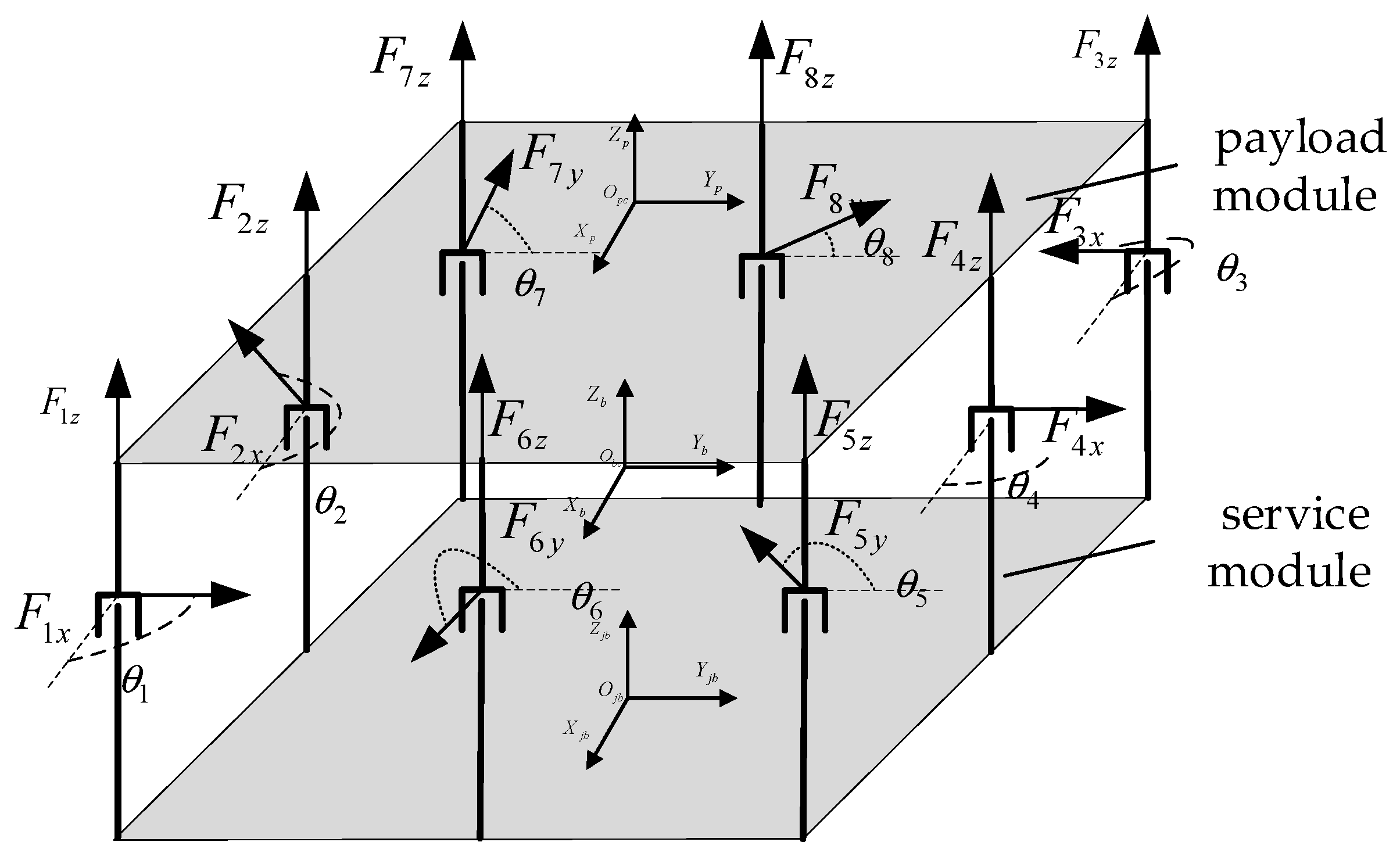
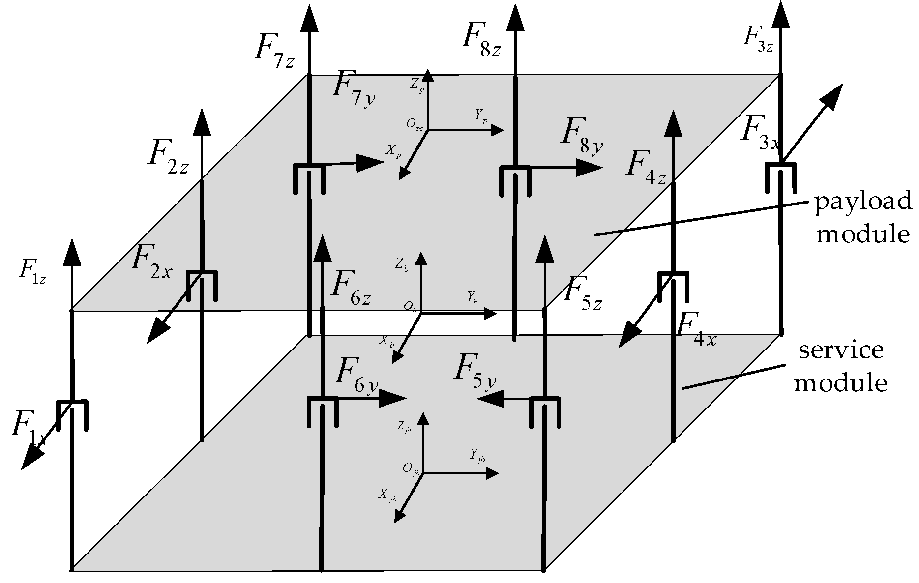
3.1. Configuration of the Lorentz Force Magnetic Bearing Group
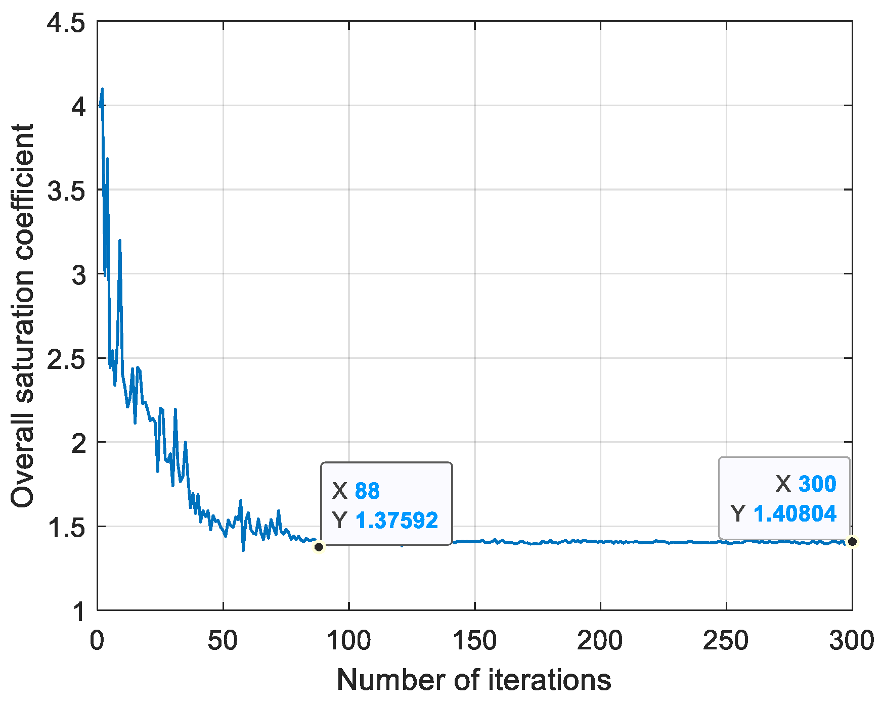
3.2. Manipulation Law Based on the Adaptive Weighted Pseudo-Inverse Method
- Real-time saturation monitoring: Calculate the saturation of each magnetic bearing from sensor data.
- Dynamically adjust the weight: If (close to saturation), the corresponding weight is reduced as follows:
- 3.
- When the displacement or current is close to the threshold (type 37–38), the high-risk constraints (such as mechanical collisions or coil overheating) are preferentially limited by adjusting α, β.
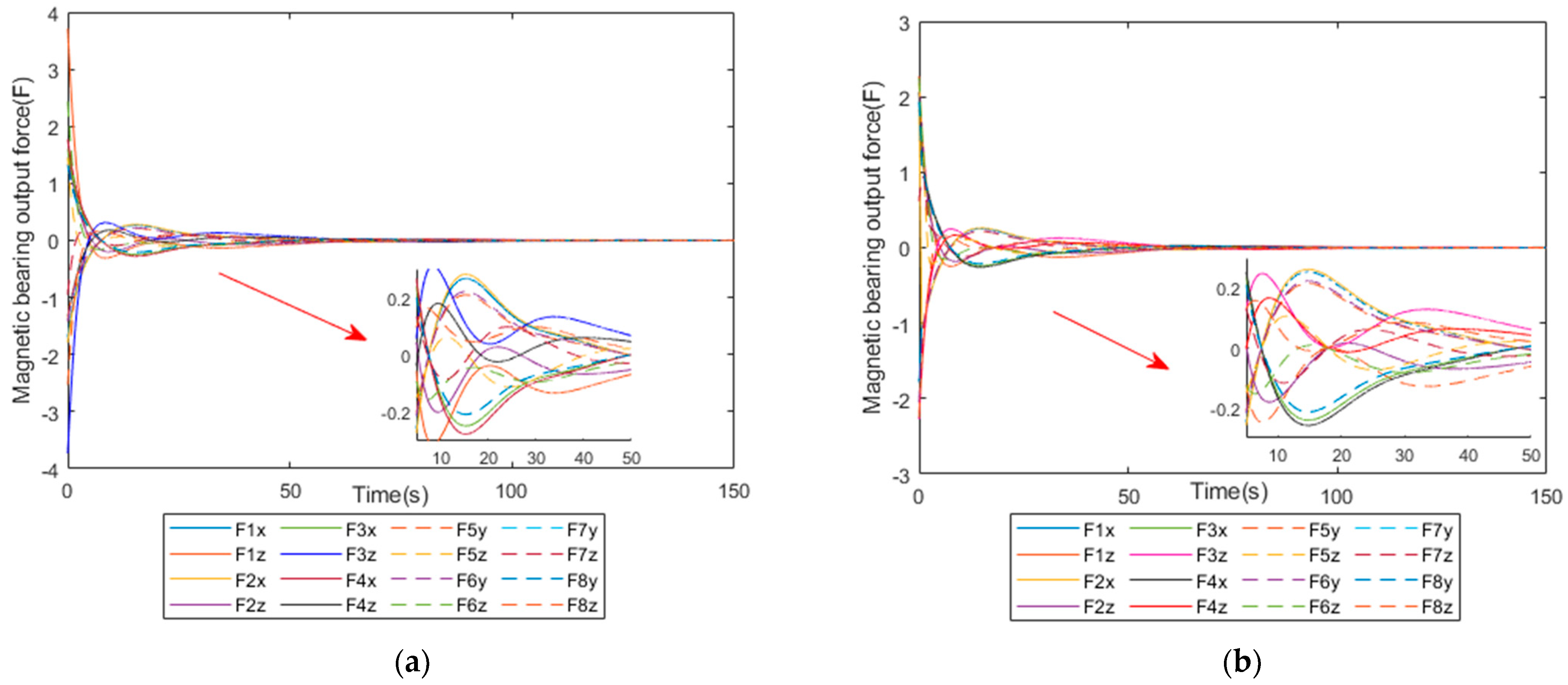
4. Simulation
5. Conclusions
Author Contributions
Funding
Institutional Review Board Statement
Informed Consent Statement
Data Availability Statement
Conflicts of Interest
References
- Xiang, B.; Wu, S.; Wen, T.; Liu, H.; Peng, C. Design, modeling, and validation of a 0.5 kWh flywheel energy storage system using magnetic levitation system. Energy 2024, 308, 132867. [Google Scholar] [CrossRef]
- Gerlach, B.; Ehinger, M.; Raue, H.K.; René, S. Gimballing magnetic bearing reaction wheel with digital controller. In Proceedings of the 6th International ESA Conference on Guidance, Navigation and Control Systems, San Francisco, CA, USA, 17–20 October 2005. [Google Scholar]
- Li, J.; Xiao, K.; Liu, K.; Hou, E. Mathematical model of a vernier gimballing momentum wheel supported by magnetic bearings. In Proceedings of the 13th International Symposium on Magnetic Bearings, Charlottesville, VA, USA, 6–9 August 2012. [Google Scholar]
- Fang, J.; Wang, P. Identification of magnetic parameters of magnetic bearings for control moment gyroscope. Chin. J. Inert. Technol. 2007, 221–224. [Google Scholar]
- Shi, S.; Jiancheng, F.; Wei, Z.; Gang, L.; Yong, Q.; Baodong, F.; Hu, L. High-precision attitude control method based on MSCMG large-scale remote sensing satellite. Chin. J. Inert. Technol. 2017, 25, 421–431. [Google Scholar]
- Chen, F.; Wang, W.; Wang, S. Rotating Lorentz Force Magnetic Bearings’ Dynamics Modeling and Adaptive Controller Design. Sensors 2023, 23, 8543. [Google Scholar] [CrossRef] [PubMed]
- Yang, H.; Liu, L.; Liu, Y.; Li, X. Modeling and Micro-vibration Control of Flexible Cable for Disturbance-Free Payload Spacecraft. Microgravity Sci. Technol. 2021, 33, 46. [Google Scholar] [CrossRef]
- Du, L.; Luo, Y.; Ji, L.; Yang, F.; Zhang, Y.; Xie, S. Comprehensive parametric model and decoupling design of a Stewart platform for a large spaceborne optical load. Acta Astronaut. 2025, 226 Pt 2, 119–134. [Google Scholar] [CrossRef]
- Pedreiro, N. Spacecraft architecture for disturbance-free payload. J. Guid. Control Dyn. 2003, 26, 794–804. [Google Scholar] [CrossRef]
- Pedreiro, N.; Gonzales, M.A.; Foster, B.W. Agile Disturbance-free payload. In Proceedings of the AIAA Guidance, Navigation, and Control Conference, San Ftancisco, CA, USA, 15–18 August 2005. [Google Scholar]
- Gonzales, M.A.; Pedreiro, N.; Roth, D.E. Unprecedented vibration isolation demonstration using the disturbance-free payload concept. In Proceedings of the AIAA Guidance, Navigation, and Control Conference and Exhibit, Providence, Rhode Island, 16–19 August 2004; p. 5247. [Google Scholar] [CrossRef]
- Wang, J. Research on the Integrated Control Method of Disturbance Isolation Load and Satellite Platform; Harbin Institute of Technology: Harbin, China, 2016. [Google Scholar]
- Yang, H.; Liu, L.; Li, X. Hyperstatic space science satellite separated active vibration isolation technology. China Space Sci. Technol. 2021, 41, 102–110. [Google Scholar]
- Nordt, A.; Dewell, L.; Zeledon, R.; Shaw-Lecerf, M.; Gilbertson, M.; Tajdaran, K.; Sireci, A.; Petrovsky, A.; Ruiz, A. Non-contact vibration isolation technology demonstration on a CubeSat. Space Telescopes and Instrumentation 2020: Optical, Infrared, and Millimeter Wave. Int. Soc. Opt. Photonics 2020, 11443, 1144332. [Google Scholar]
- Zhang, W.; Zhao, Y.; Liao, H. Design of dynamic and static isolation, master-slave cooperative control dual super satellite platform. Shanghai Aerosp. 2014, 31, 7–11+30. [Google Scholar]
- Zhang, W.; Liao, H.; Yuan, J. Dual-Super Satellite Platform for Master-Slave Collaborative Control of Static and Dynamic Isolation. CN201410610456.X, 1 April 2015. [Google Scholar]
- Kong, Y.; Huang, H. Performance enhancement of disturbance-free payload with a novel design of architecture and control. Acta Astronaut. 2019, 159, 238–249. [Google Scholar] [CrossRef]
- He, Z.; Feng, X.; Zhu, Y.; Yu, Z.; Li, Z.; Zhang, Y.; Wang, Y.; Wang, P.; Zhao, L. Progress of Stewart Vibration Platform in Aerospace Micro–Vibration Control. Aerospace 2022, 9, 324. [Google Scholar] [CrossRef]
- Zhang, Y.; Sheng, C.; Hu, Q.; Li, M.; Guo, Z.; Qi, R. Dynamic analysis and control application of vibration isolation system with magnetic suspension on satellites. Aerosp. Sci. Technol. 2018, 75, 99–114. [Google Scholar] [CrossRef]
- Zhang, W.; Hong, Z.; Song, X. New Maglev Actuator Combination Layout and High Reliability Redundancy Design Method. CN201810638605.1, 29 May 2020. [Google Scholar]
- Zhang, J.; Zhang, W.; Wang, H. Combination Distribution Method and System of Actuators of Different Specifications for Double Super Satellite. CN202311085427.1, 5 December 2023. [Google Scholar]
- Wang, Z.; Zhang, J.; Yang, L. Weighted pseudo-inverse based control allocation of heterogeneous redundant operating mechanisms for distributed propulsion configuration. Energy Procedia 2019, 158, 1718–1723. [Google Scholar] [CrossRef]
- Wu, W.; Shen, L.; Jin, W. Assuming that the speed obeys the truncated normal distribution of the bus platoon density discrete model. J. South China Univ. Technol. Nat. Sci. Ed. 2013, 41, 44–50. [Google Scholar]
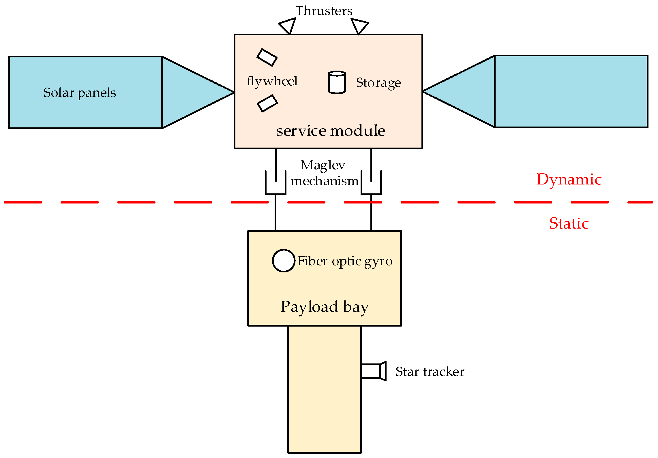
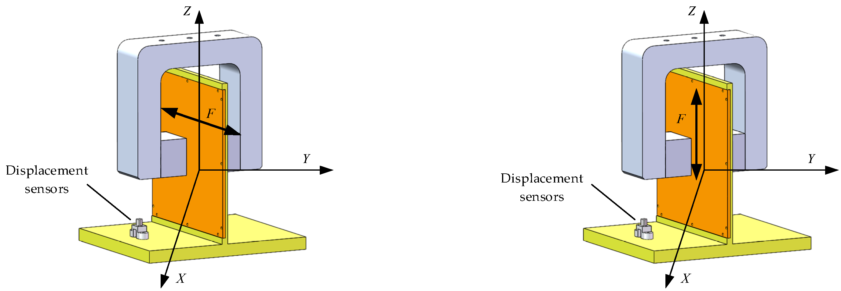
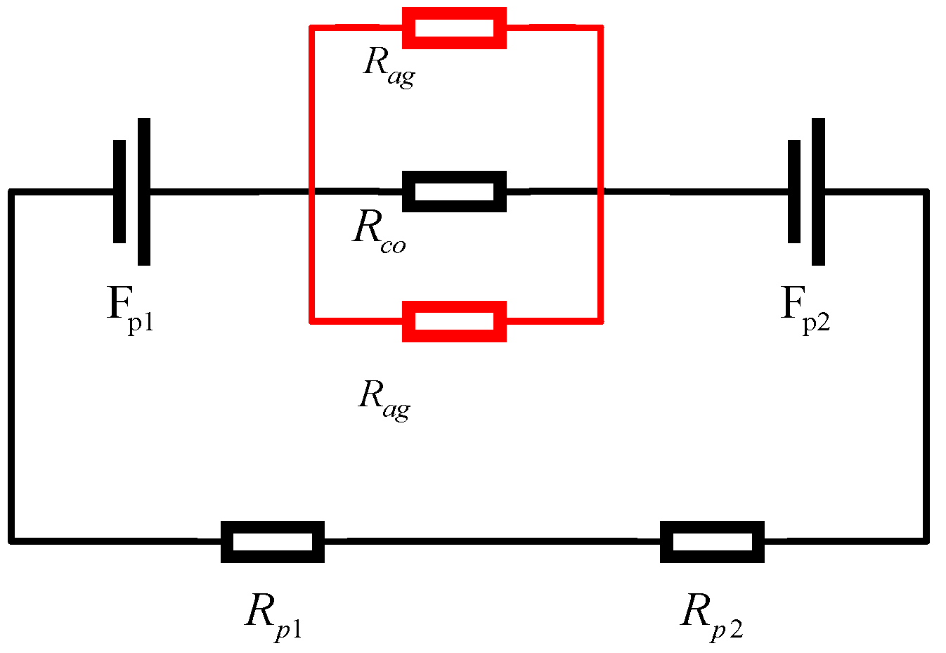
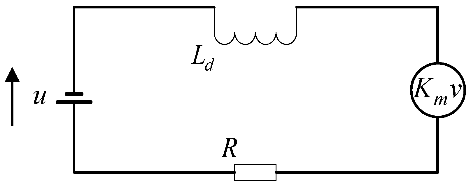


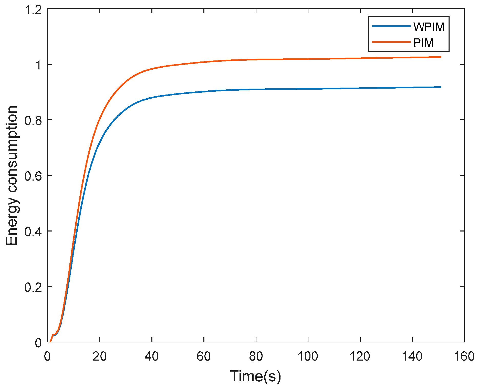

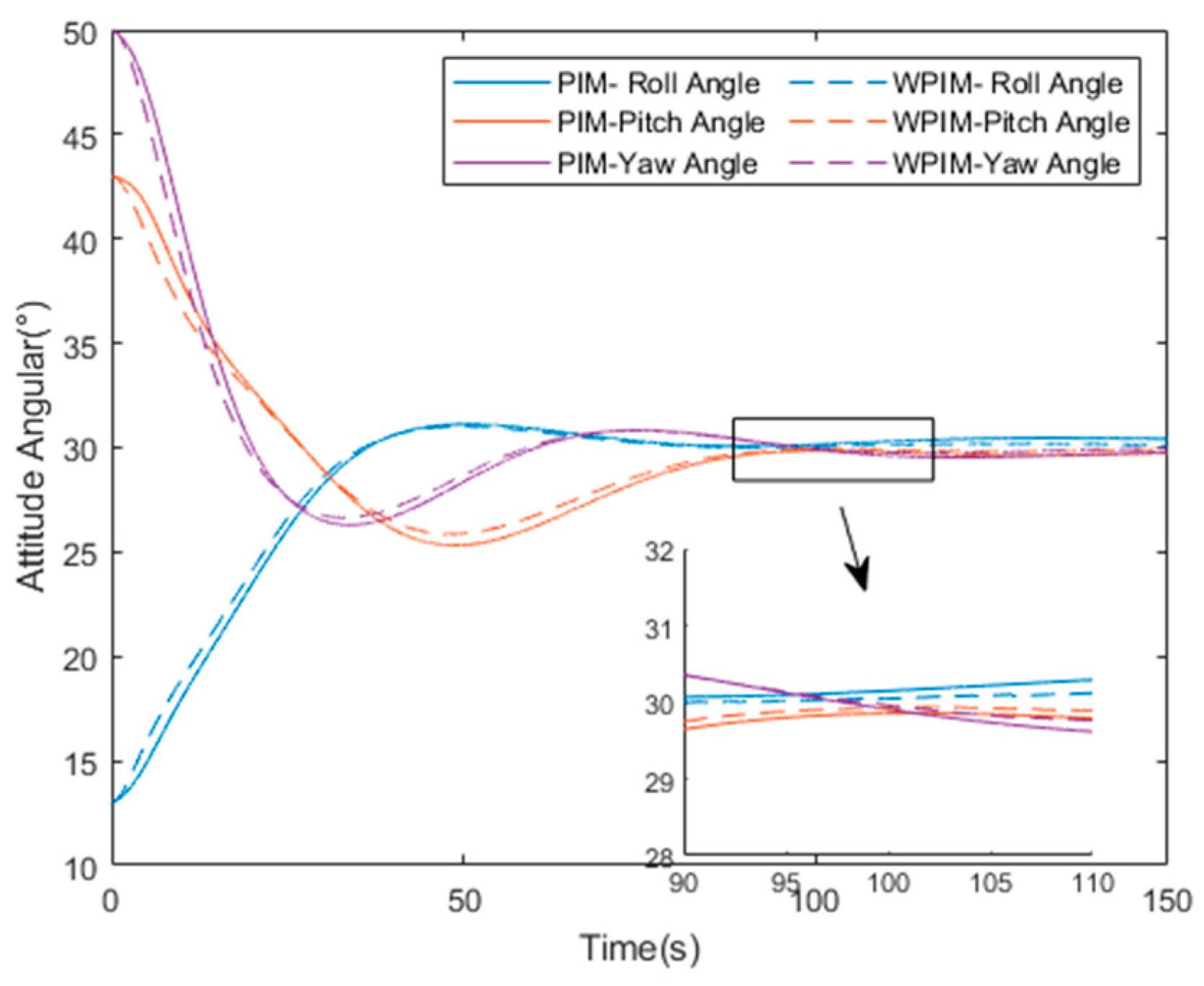
| Formula Symbol | Definition |
|---|---|
| Coercivity of magnetic steel (A/m) | |
| Magnetization length of the left and right permanent magnets (m) | |
| Circumferential cross-sectional area of the left and right permanent magnets (m2) | |
| Vacuum permeability and relative permeability of soft magnetic materials | |
| Working air gap length (m) | |
| Magnet thickness of left and right permanent magnets (m) |
| Formula Symbol | Definition |
|---|---|
| Back electromotive force (V) | |
| Coil inductance coefficient (H) | |
| Coil current (A) | |
| Back electromotive force coefficient (with magnetic field strength B, coil turns N, and coil length Lx)-related (V·s/m) | |
| Coil displacement (m) | |
| Coil input voltage (V) | |
| Coil resistance (Ω) |
| Magnetic Bearing | Installation Location | Output Force Vector Direction | ||||
|---|---|---|---|---|---|---|
| X | Y | Z | X | Y | Z | |
| A1 | 0 | × | √ | √ | ||
| A2 | 0 | 0 | √ | √ | √ | |
| A3 | 0 | × | √ | √ | ||
| A4 | 0 | 0 | × | √ | √ | |
| A5 | 0 | √ | √ | √ | ||
| A6 | 0 | 0 | √ | × | √ | |
| A7 | 0 | √ | × | √ | ||
| A8 | 0 | 0 | √ | √ | √ | |
| Magnetic Bearing | Installation Location | Output Force Vector Direction | ||||
|---|---|---|---|---|---|---|
| X | Y | Z | X | Y | Z | |
| A1 | 0 | √ | × | √ | ||
| A2 | 0 | 0 | √ | × | √ | |
| A3 | 0 | √ | × | √ | ||
| A4 | 0 | 0 | √ | × | √ | |
| A5 | 0 | × | √ | √ | ||
| A6 | 0 | 0 | × | √ | √ | |
| A7 | 0 | × | √ | √ | ||
| A8 | 0 | 0 | × | √ | √ | |
| Parameters | Stats |
|---|---|
| m (kg) | 10 |
| L1 (m) | 1.3 |
| L2 (m) | 1.1 |
| K (N/A) | 29 |
| (V·s/m) | 24 |
| (H) | 0.005 |
| Kb (N/(m/s)) | 5 |
| Δx,Δy,Δz (m) | 0.005 |
| Initial attitude angle (°) | |
| Target attitude angle (°) | [30 30 30]T |
Disclaimer/Publisher’s Note: The statements, opinions and data contained in all publications are solely those of the individual author(s) and contributor(s) and not of MDPI and/or the editor(s). MDPI and/or the editor(s) disclaim responsibility for any injury to people or property resulting from any ideas, methods, instructions or products referred to in the content. |
© 2025 by the authors. Licensee MDPI, Basel, Switzerland. This article is an open access article distributed under the terms and conditions of the Creative Commons Attribution (CC BY) license (https://creativecommons.org/licenses/by/4.0/).
Share and Cite
Wang, C.; Li, L.; Wang, W.; Zhao, Y.; Li, B.; Ren, Y. Design of a Lorentz Force Magnetic Bearing Group Steering Law Based on an Adaptive Weighted Pseudo-Inverse Law. Sensors 2025, 25, 3242. https://doi.org/10.3390/s25103242
Wang C, Li L, Wang W, Zhao Y, Li B, Ren Y. Design of a Lorentz Force Magnetic Bearing Group Steering Law Based on an Adaptive Weighted Pseudo-Inverse Law. Sensors. 2025; 25(10):3242. https://doi.org/10.3390/s25103242
Chicago/Turabian StyleWang, Chenyu, Lei Li, Weijie Wang, Yanbin Zhao, Baiqi Li, and Yuan Ren. 2025. "Design of a Lorentz Force Magnetic Bearing Group Steering Law Based on an Adaptive Weighted Pseudo-Inverse Law" Sensors 25, no. 10: 3242. https://doi.org/10.3390/s25103242
APA StyleWang, C., Li, L., Wang, W., Zhao, Y., Li, B., & Ren, Y. (2025). Design of a Lorentz Force Magnetic Bearing Group Steering Law Based on an Adaptive Weighted Pseudo-Inverse Law. Sensors, 25(10), 3242. https://doi.org/10.3390/s25103242


