1. Introduction
Hollow-core anti-resonant fiber (HC-ARF) is a type of hollow-core fiber that offers advantages over other types with the features of simple structure and utilizing air as the material for transmitting light. This leads to excellent characteristics such as low dispersion, low time delay, and high damage threshold [
1]. Due to its unique merits, HC-ARFs have become a hot topic in the field of optical fibers and have a wide range of applications, such as fiber sensing, laser transmission [
2], mid-infrared lasers [
3], etc. With the increasing requirements of optical transmission systems, such as longer transmission distances, faster transmission bit rates, and high-power delivery, it is necessary to dedicate efforts toward exploring high-performance hollow-core anti-resonant fibers.
Currently, great progress has been made on the structure of HC-ARFs to realize better performance, including low confinement loss and high birefringence, etc. In 2018, a nested-tube anti-resonant fiber was proposed, achieving a confinement loss of 2 dB/km at 1512 nm and a loss below 16 dB/km in the wavelength range of 1302–1637 nm [
4]. Also, a nested-type HC-ARF consisting of six nested tubes was proposed to achieve a confinement loss of 1.3 dB/km at 1450 nm and a loss below 1.4 dB/km in the wavelength range of 1420–1460 nm [
5]. In 2019, Bradley et al. further optimized the structure and fabricated a nested-type fiber with a loss of only 0.65 dB/km in the C and L communication bands [
6]. Also, in 2019, a nested HC-ARF composed of six nested tubes was designed, realizing a loss below 10 dB/km in the wavelength range of 1240–1940 nm, with the lowest loss of 6.6 dB/km at 1550 nm [
7]. In 2020, a nested HC-ARF was realized, consisting of six nested tubes with an ultralow loss of 0.32 dB/km in the wavelength range of 1530–1625 nm [
8]. In 2021, a nested structure with five cladding tubes was fabricated, with the loss reduced to 0.22 dB/km at 1625 nm [
9], and a connected-ring HC-ARF was designed with a minimum loss of 3.69 × 10
−3 dB/km [
10]. In 2022, a three-nested structure was proposed to achieve a loss below 0.174 dB/km in the wavelength range of 1530–1565 nm and below 0.22 dB/km in the wavelength range of 1260–1360 nm, respectively [
11]. In 2023, a novel crescent-shaped core HC-ARF was introduced to realize a loss of less than 0.1 dB/km over a band range of 600 nm and a significant birefringence of less than 10
−5 through asymmetric shaping [
12]. A new five-tube nested double C-type HC-ARF was realized to obtain single-polarization single-mode transmission at 1550 nm with a bandwidth of 150 nm and an ultra-low confinement loss of 2.8 × 10
−3 dB/km [
2]. A negatively curved core AR-HCF was studied to realize a high birefringence of 1.3 × 10
−4 and a low confinement loss of 6.1 dB/km at 1550 nm [
13]. Still in 2023, a HC-ARF with a nested and double-cladding structure was presented to obtain the minimum confinement loss of 4 × 10
−4 dB/km at 1550 nm and a high-order mode loss ratio of up to 20,000 [
14].
In order to further optimize the performance of HC-ARF, a novel nested HC-ARF is proposed in this paper to realize low confinement loss and a large effective mode area with a wide operating wavelength range simultaneously. In the cladding region, six elliptical tubes are combined and nested with six large circular tubes, and six small circular tubes are introduced in the gaps of the elliptical tubes. Different cladding tube thicknesses and cladding layer thicknesses are utilized to reduce the confinement loss, enhance the effective mode area, and increase the transmission band. The effects of different structural parameters on the confinement loss and the effective mode area are investigated in detail according to the priority of their influences on performance.
2. Structure Design and Basic Theory
The structural design is considered in the order of decreasing confinement loss, enlarging the effective mode area, and widening the operating wavelength band. The involved structural parameters include the number of cladding tubes N, the thicknesses of the elliptical and circular cladding tubes, the thicknesses of the cladding layer, the core diameter, the size of the elliptical cladding tube, and the diameter of the small circular cladding tube.
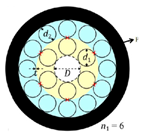
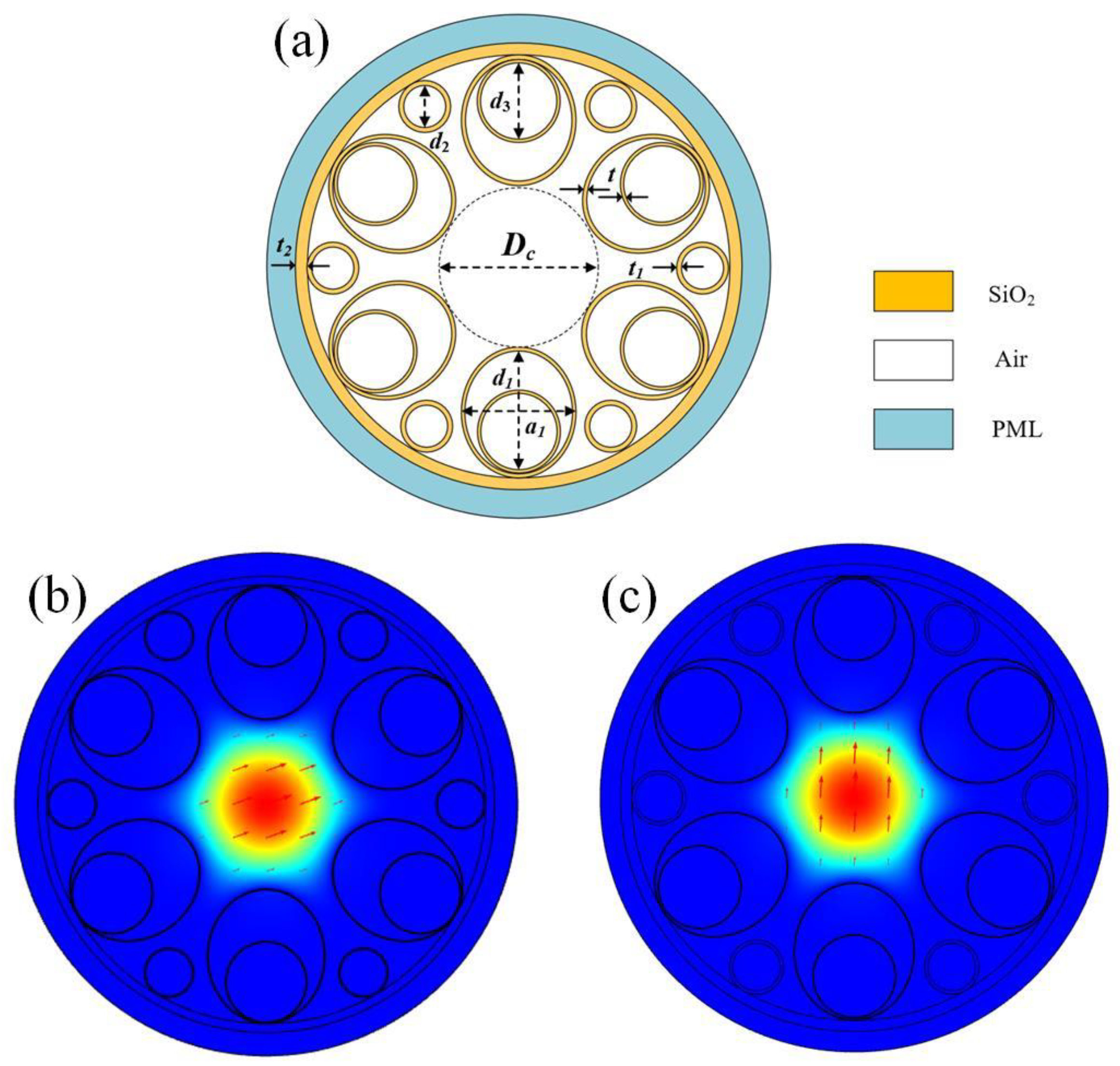
Figure 1a shows the cross-section of the HC-ARF structure with the number of cladding tubes N = 6, and each cladding tube contains one small circular cladding tube and one elliptical tube nested within a large circular cladding tube. The core diameter is
Dc, the elliptical cladding tube has a long axis of
d1 and a short axis of a
1, the diameter of the large circular cladding tubes is
d3, the diameter of the small circular cladding tubes is
d2, the thickness of the elliptical and large circular cladding tubes is t, the thickness of the small circular cladding tubes is
t1, and the thickness of the cladding layer is
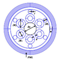
t2. The outermost layer is a perfectly matched layer (PML), typically set to be 2–3 times the wavelength. Both the cladding tubes and the cladding layer are silica, whose refractive index is wavelength-dependent and can be calculated using the Sellmeier equation [
15].
According to the anti-resonance condition, when the wavelength satisfies the anti-resonance condition, the optical mode field is confined to the core region. However, when the wavelength satisfies the resonance condition, optical mode field leakage occurs.
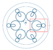
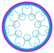
Figure 1b,c show the electric field distribution of the fundamental mode in the x-polarization and y-polarization, respectively, at the wavelength of 1550 nm. It can be observed that the optical mode field is well confined within the fiber core at the anti-resonance wavelength.
A full-vector finite element method combined with PML boundary conditions is adopted to analyze the properties of the proposed HC-ARF.
The confinement loss and the dispersion are the crucial parameters to measure the transmission characteristics of the HC-ARF, which can be calculated as [
16,
17]:
where
neff is the effective mode refractive index,
Im (
neff) and
Re (
neff) are the imaginary and real part of the effective mode refractive index, λ is the wavelength, and c is the speed of light.
The effective mode area is another important parameter to measure the performance of the fiber, which is [
18]:
where
E is the transverse component of the electric field propagating inside the fiber, and
is the cross section of the fiber.
3. Analysis of Results and Discussion
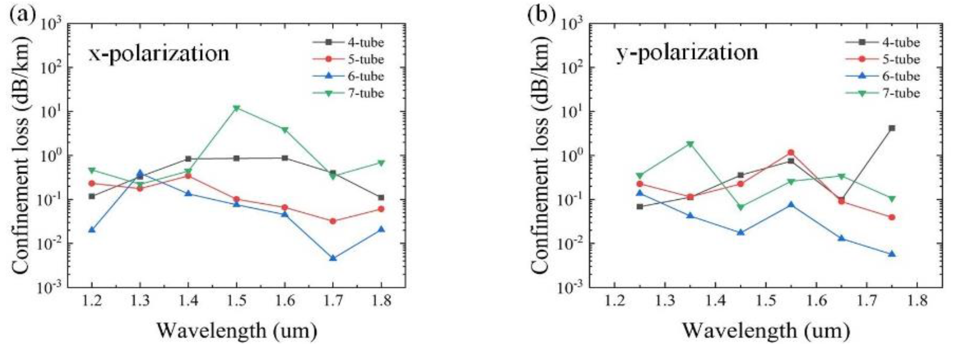
The effects of the number of cladding tubes N, as the most important parameter, on the confinement loss are studied first. Based on the practical application requirements, the initial data are set as follows:
Dc = 50 µm,
d1= 40 μm, a
1 = 35 μm,
d2 = 14 μm,
d3 = 24 μm,
t = 0.5 μm,
t1 = 1 μm, and
t2 = 1.3 μm. The variation of the confinement loss as a function of the wavelength with different numbers of cladding tubes N = 4, 5, 6, and 7 for x and y polarizations is shown in
Figure 2. It can be seen that the overall confinement loss is lowest for N = 6. This is mainly because the greater the number of cladding tubes, the stronger the ability to confine the light, which has lower confinement loss [
19]. However, it is not the greater the number, the lower the confinement loss. The reason is that with the increase of N, the cladding tube gap will decrease, which can strengthen the resonance between the cladding tubes and cause increased confinement loss. Therefore, in the subsequent analysis, the number of cladding tubes N = 6 is adopted, as shown in
Figure 1a.
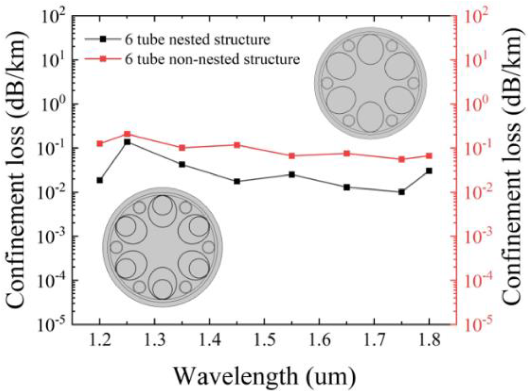
The reason why the nested cladding tubes are selected can be observed from
Figure 3, which illustrates the variation of confinement loss with the nested and non-nested structures. It is evident that the nested tube structure exhibits lower confinement loss compared to the non-nested tube structure. It is easily understandable that adding nested tubes can effectively reduce the adverse effects caused by the gaps between the tubes, thereby increasing the ability to constrain light.
The influences of the parameters on the performance of the HC-ARF are investigated one by one within the wavelength range of 1200–2200 nm. The thickness of the elliptical and large circular cladding tubes, t, has the strongest effects, which can be calculated based on the following equation [
20]:
where n
1 represents the refractive index of silicon,
n0 represents the refractive index of air, λ represents the wavelength, and m represents the order of resonance. The wavelength band is relatively wide with m = 1 and m = 2.
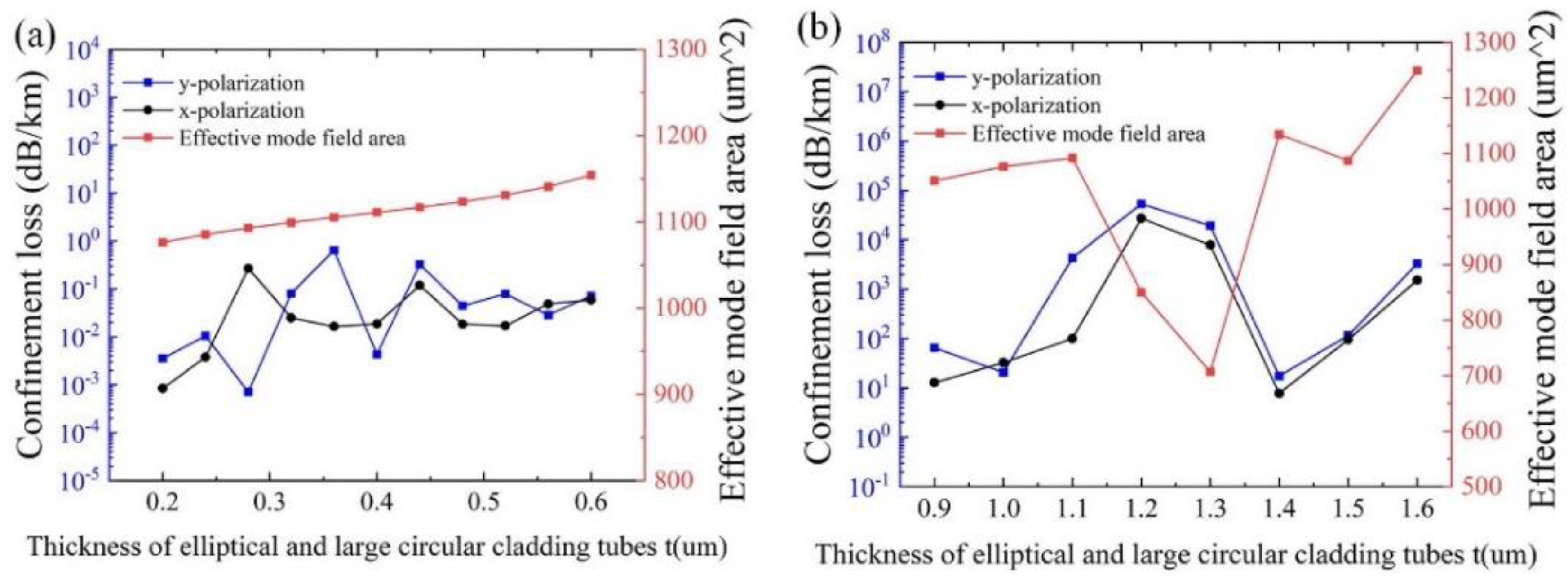
Figure 4a,b show the effects of t on the confinement loss and the effective mode area with λ = 1550 nm for different m, and other initial parameters remain unchanged, respectively. As can be seen from
Figure 4a, both the confinement losses and the effective mode area increase with the increase of t. The physical reason is that the narrowed gap between the cladding tubes, due to the increased t, can strengthen the resonance between the cladding tubes, resulting in increased confinement loss and effective mode area. It can be observed that the overall effective mode area remains above 1000 µm
2, and the minimum confinement loss of 7.04 × 10
−4 dB/km is obtained at t = 0.28 μm. As indicated in
Figure 4b, the overall confinement losses deteriorate, with values above the order of 10. Thus, m = 1 is adopted.
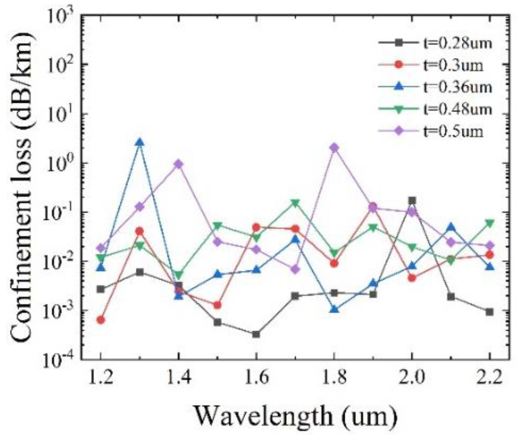
To determine the optimal value of t, the confinement loss as a function of the wavelength for different t, with other initial parameters remaining unchanged, is shown in
Figure 5. It can be seen that for
t = 0.28 μm, the lowest loss of 2.79 × 10
−4 dB/km is achieved at λ = 1450 nm, and the overall loss is below 0.39 dB/km. When
t = 0.3 μm, the lowest loss of 6.45 × 10
−4 dB/km is obtained at λ = 1200 nm with the overall loss below 0.13 dB/km. For
t = 0.36 μm, the lowest loss of 9.43 × 10
−4 dB/km is reached at λ = 1250 nm, with the overall loss below 3.09 dB/km. When
t = 0.48 μm, the lowest loss of 3.8 × 10
−3 dB/km is obtained at λ = 2150 nm, with the overall loss below 0.16 dB/km. For
t = 0.5 μm, the lowest loss is 6.85 × 10
−3 dB/km at λ = 1700 nm, with the overall loss below 2.04 dB/km. The comparison indicates that the lowest confinement loss can be achieved at
t = 0.3 μm. As a consequence, the optimal t is determined to be 0.3 μm.
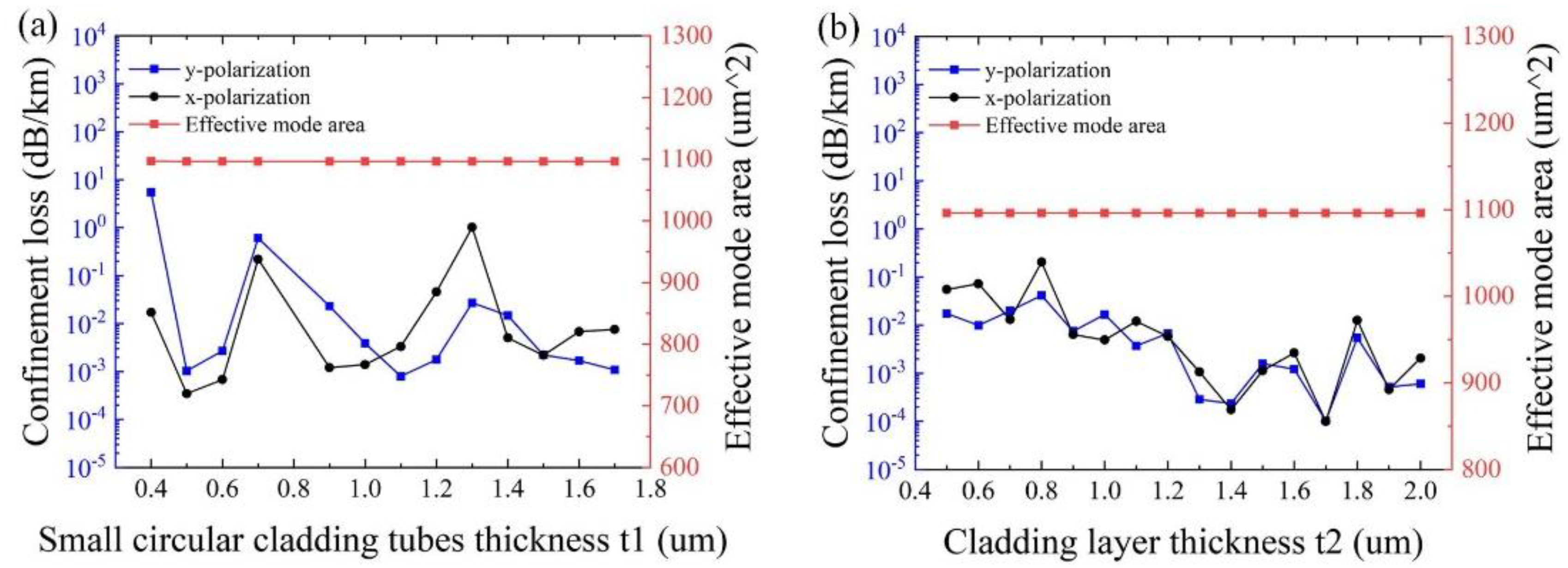
Figure 6a,b show the influence of the thickness of small circular cladding tubes
t1 and the cladding layer
t2, with other initial parameters remaining unchanged, respectively. As can be seen from
Figure 6a, the minimum confinement loss of 2.85 × 10
−4 dB/km is obtained at
t1 = 0.5 μm, and the effective mode area almost keeps stabilizing at ~1100 μm
2. As shown in
Figure 6b, the effects of the thickness of the cladding layer
t2 on the effective mode area are negligible. The variation of the thickness of the cladding layer
t2 has less impact on the confinement loss than that of the thickness of the elliptical and large circular cladding tubes t and the small circular cladding tubes
t1. This is because the farther the distance from the core, the smaller the impact on the core mode. In particular, the minimum confinement loss of 1.03 × 10
−4 dB/km is realized at
t2 =1.7 μm for both polarizations. Therefore, it is reasonable to set
t1 = 0.5 μm and
t2 = 1.7 μm.
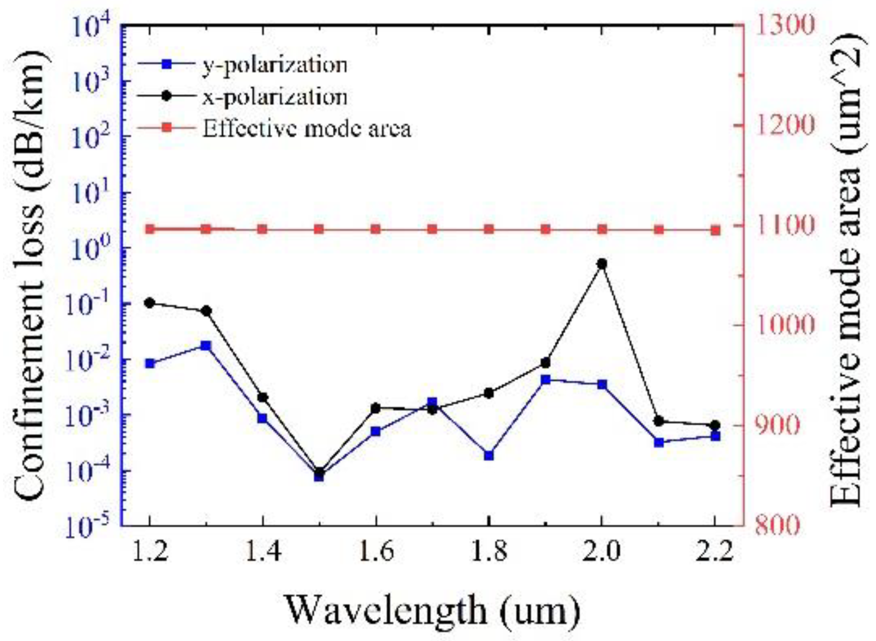
Figure 7 presents the confinement loss and the effective mode area as a function of the wavelength with optimized tube thickness
t,
t1 and
t2 and other initial parameters remain unchanged. It can be observed that in the transmission band of 1000 nm, the confinement loss can reach the minimum value of 7.91 × 10
−5 dB/km at 1500 nm, with a large effective mode area of 1096.3 μm
2 simultaneously. It should be pointed out that the maximum confinement loss of y polarization is less than 0.018 dB/km, illustrating the excellent performance of low confinement loss.
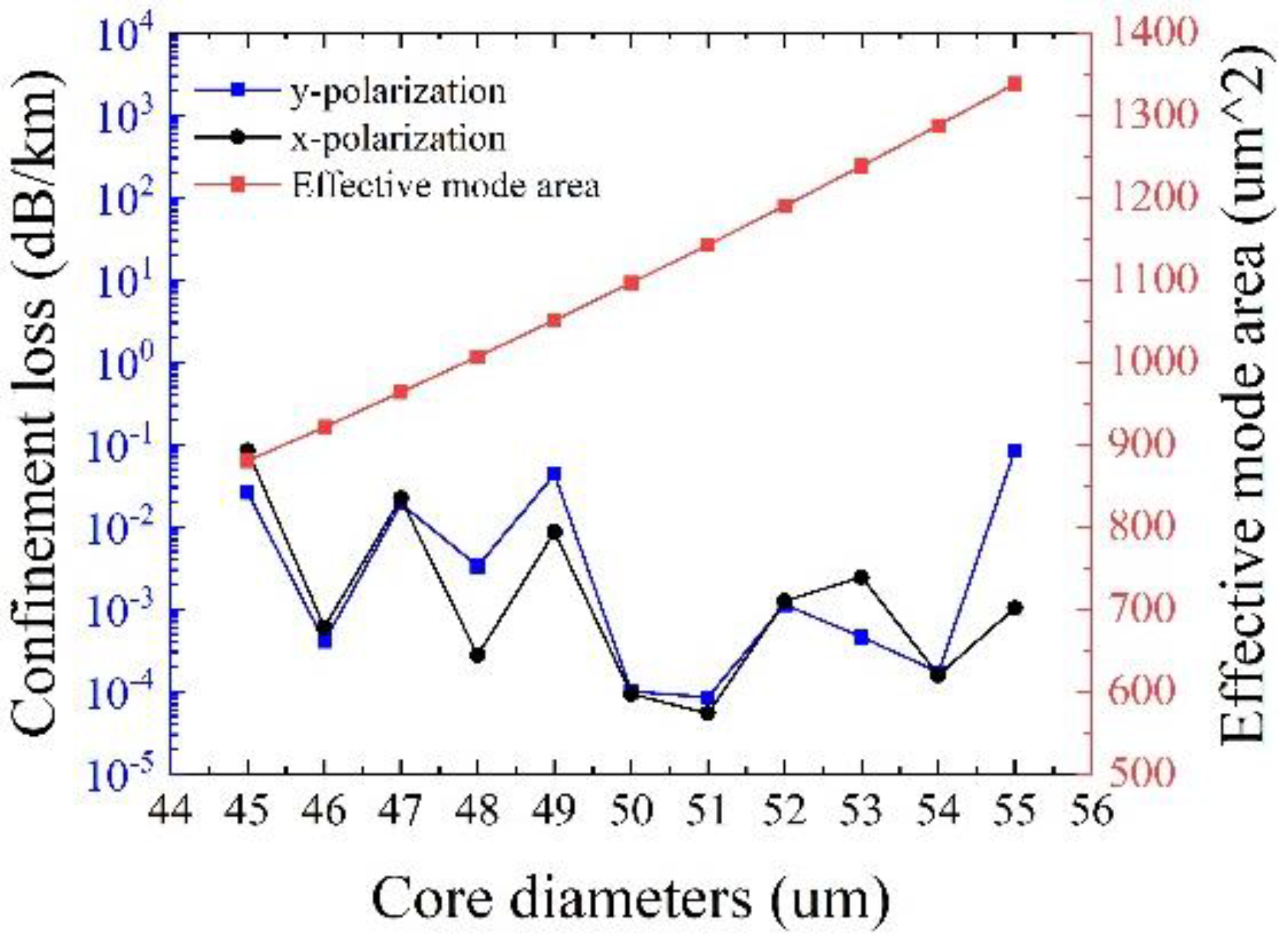
Figure 8 shows the effects of the core diameter
Dc on the confinement loss and the effective mode area at λ = 1550 nm, with other initial parameters remaining unchanged. It can be observed that the effective mode area increases with the core diameter, and the minimum confinement loss of 8.48 × 10
−5 dB/km can be achieved at
Dc = 51 μm, with a large effective mode area of 1142.5 μm
2 together. It should be noted that it is not that the larger the core diameter, the lower the confinement loss. It has been proven that larger core diameters often pose challenges in ensuring single-mode transmission and may increase the losses of other higher-order modes in the fiber [
21]. Consequently,
Dc = 51 μm is adopted.
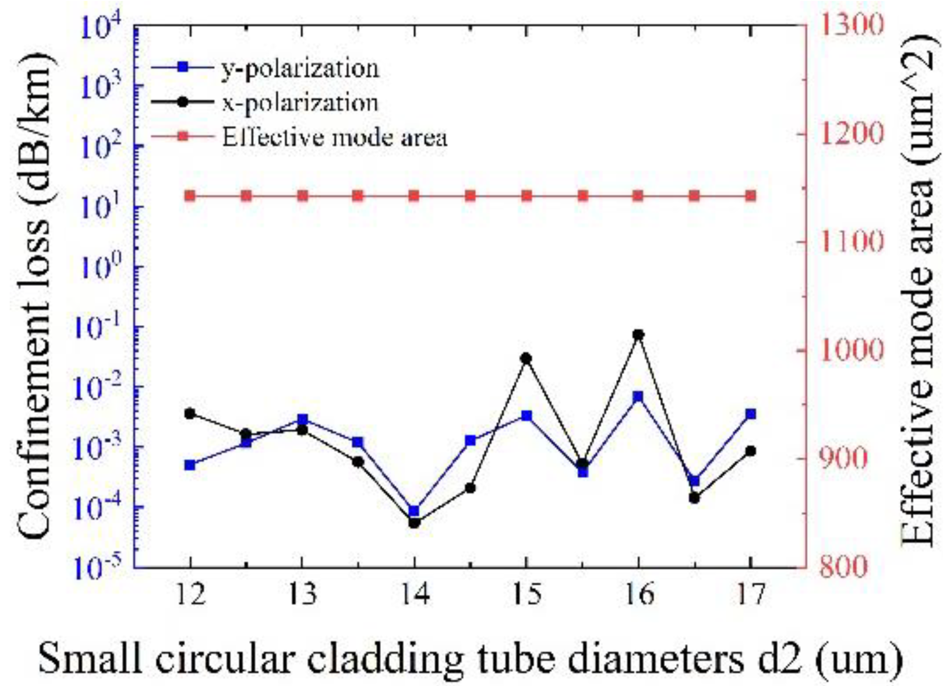
Figure 9 depicts the influences of the diameter of small circular cladding tubes
d2 on the confinement loss and the effective mode area at λ = 1550 nm, with other initial parameters remaining unchanged. It is clear that the effects of
d2 on the effective mode area can be neglected, and the maximum confinement loss is less than 0.1 dB/km. Especially, the minimum confinement loss of 5.42 × 10
−5 dB/km for x-polarization and 8.48 × 10
−5 dB/km for y-polarization can be realized at
d2 = 14 μm with an effective mode area of 1142.5 μm
2, demonstrating the realization of ultralow loss and large effective mode area at the same time. Therefore, the optimal value of
d2 is 14 μm.
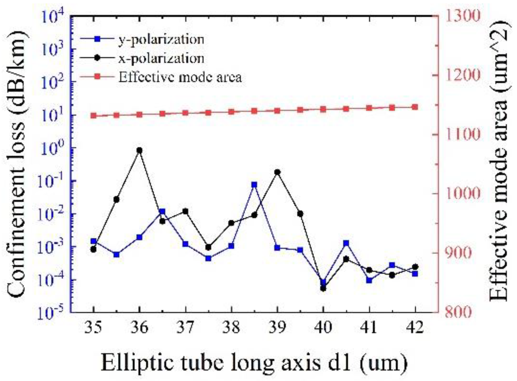
Figure 10 shows the effects of the long axis of the elliptical cladding tube
d1 on the confinement loss and the effective mode area at λ = 1550 nm, with other initial parameters remaining unchanged. It can be seen that the effective mode area slightly increases with
d1, and the minimum confinement loss of 5.42 × 10
−5 dB/km is obtained at
d1 = 40 μm for both polarizations, with an effective mode area of 1142.5 μm
2. It is easier to understand that the increase of
d1 can lead to easy mode coupling from the core to the cladding, thereby to increase the effective mode area. Hence, the optimized
d1 is determined to be 40 μm.
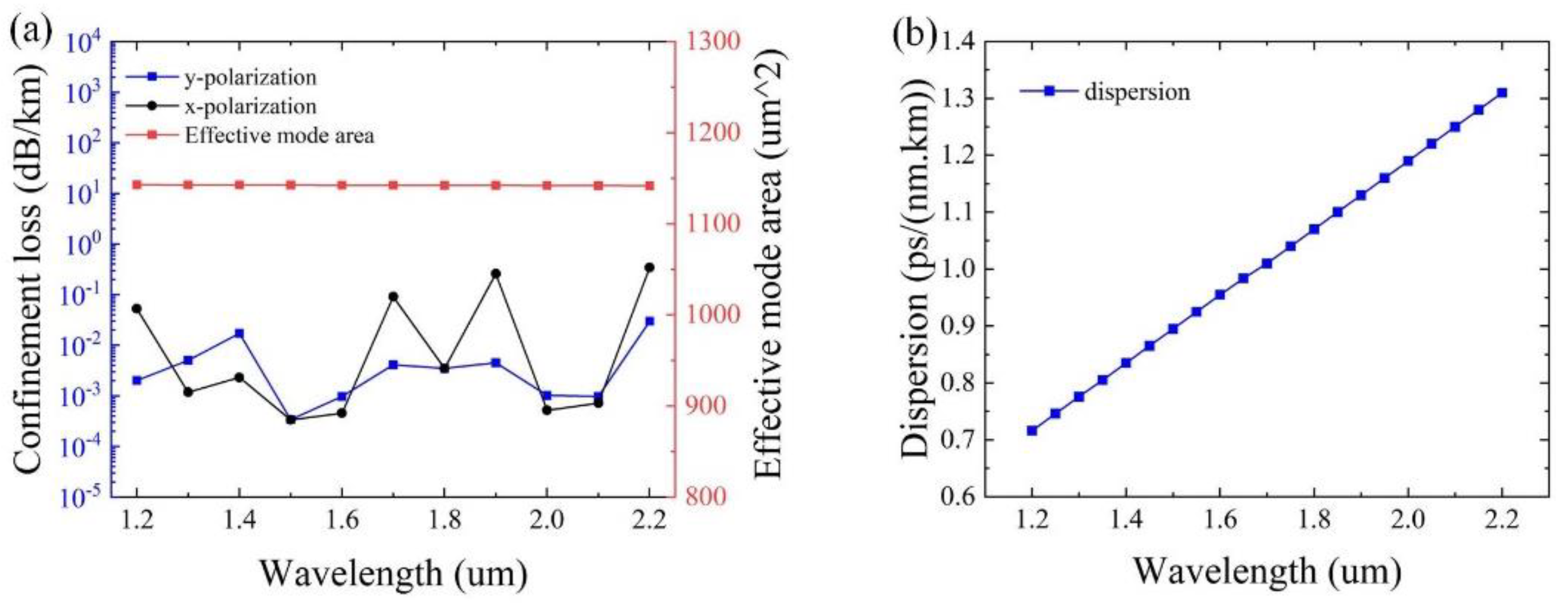
Based on the optimized parameters of
t = 0.3 μm,
t1 = 0.5 μm,
t2 = 1.7 μm,
Dc = 51 μm,
d2 = 14 μm, and
d1 = 40 μm, the optimization of the confinement loss and the effective mode area as a function of the wavelength is given in
Figure 11. From
Figure 11a, it can be observed that the effective mode area of ~1142 μm
2 can be achieved, and the confinement loss is below 0.017 dB/km for y-polarization. Particularly, the minimum confinement loss of 1.2 × 10
−4 dB/km is obtained at λ = 1500 nm for y-polarization. As can be seen from
Figure 11b, the value of the dispersion ranges from 0.7 to 1.4 ps/(nm.km), exhibiting excellent dispersion characteristics of the designed HC-ARF, implying that the optimized structure has the ability to realize ultralow loss and a large effective mode area with excellent dispersion characteristics within a wide wavelength range simultaneously.
The preparation technology of optical fibers is a crucial aspect of development. It has been indicated that the HC-ARFs offer advantages such as a simple structure and feasible manufacturing, making them more suitable for practical use. The commonly used preparation processes for HC-ARFs include stacking, extrusion, and 3D printing, among which the bundle stacking method is particularly well-suited for the practical fabrication of the optical fiber designed in this study. The process involves stacking multiple preform optical fibers and subjecting them to thermal treatment. This technique uses thermal expansion and curing processes to form a hollow-core and anti-resonant structures. By controlling the arrangement, the stacking method, and the thermal treatment of the optical fibers, it is possible to achieve the desired parameters such as hollow-core diameter, periodicity, and anti-resonant structure dimensions under certain conditions. However, it has been found that errors may occur in HC-ARFs when using the stacking method, including deformation, collapse, and displacement of the anti-resonant tubes. Among these, the displacement of the anti-resonant tubes has the least impact on the optical fiber’s transmission performance, provided that an appropriate distance between the anti-resonant tubes is maintained during preparation. Thus, with the help of the stacking method and pressure-assisted joining technology, the new type of HC-ARF proposed in this paper can be successfully fabricated in the future, provided that the errors are kept minimal.
In order to illustrate the competitiveness of the proposed HC-ARF, the comparisons with other reported structures are listed in
Table 1. It can be demonstrated that the HC-ARF presented in this paper exhibits better performance in terms of a wider transmission window, lower confinement loss, and dispersion value, as well as a larger effective mode area. In particular, the excellent characteristics of low confinement loss and dispersion, a large effective mode area, and a wide operating wavelength band can be realized simultaneously.


