
Three-Dimensional Scanning Virtual Aperture Imaging with Metasurface


Abstract
1. Introduction
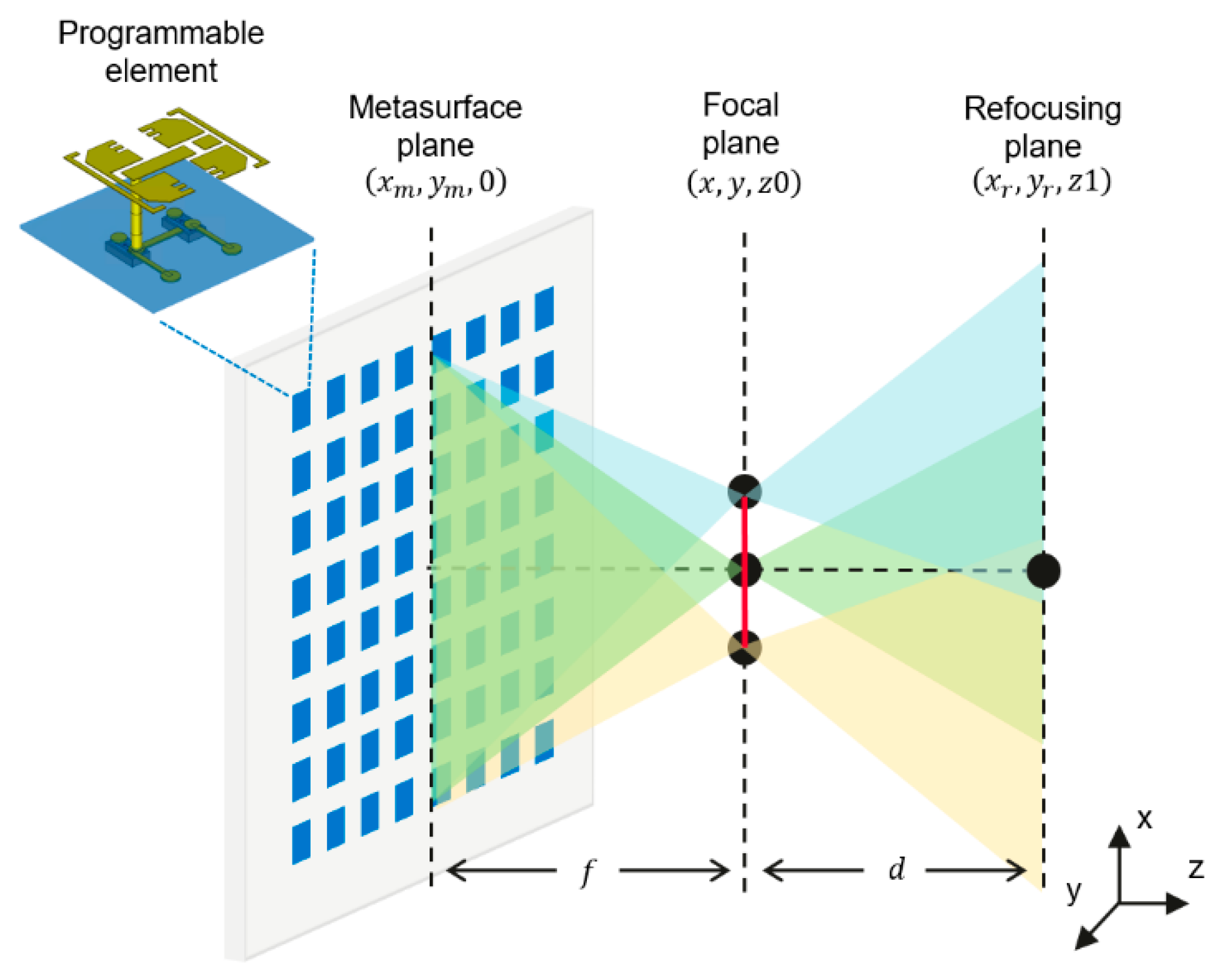
2. Methods
3. Results
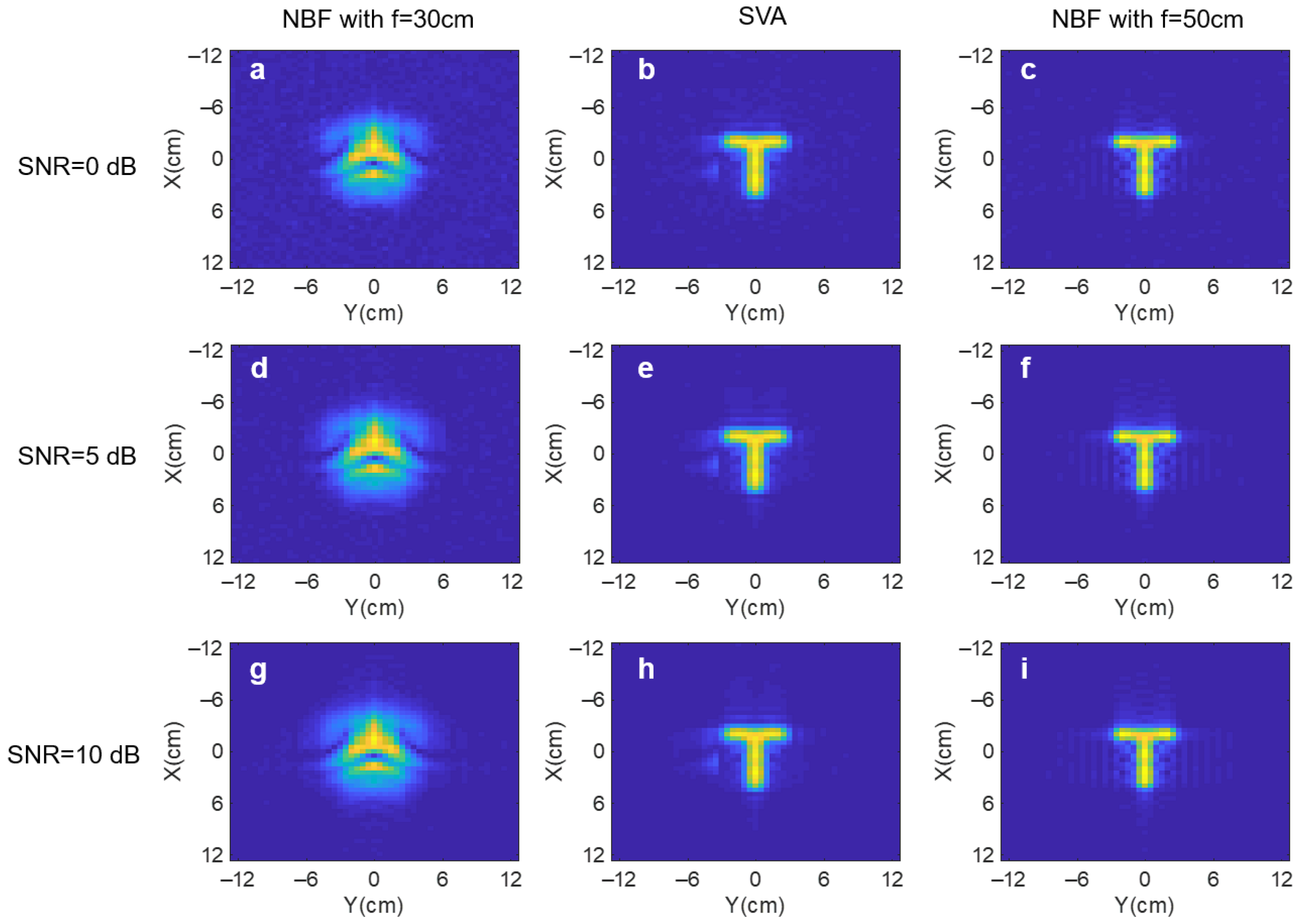
3.1. Simulation
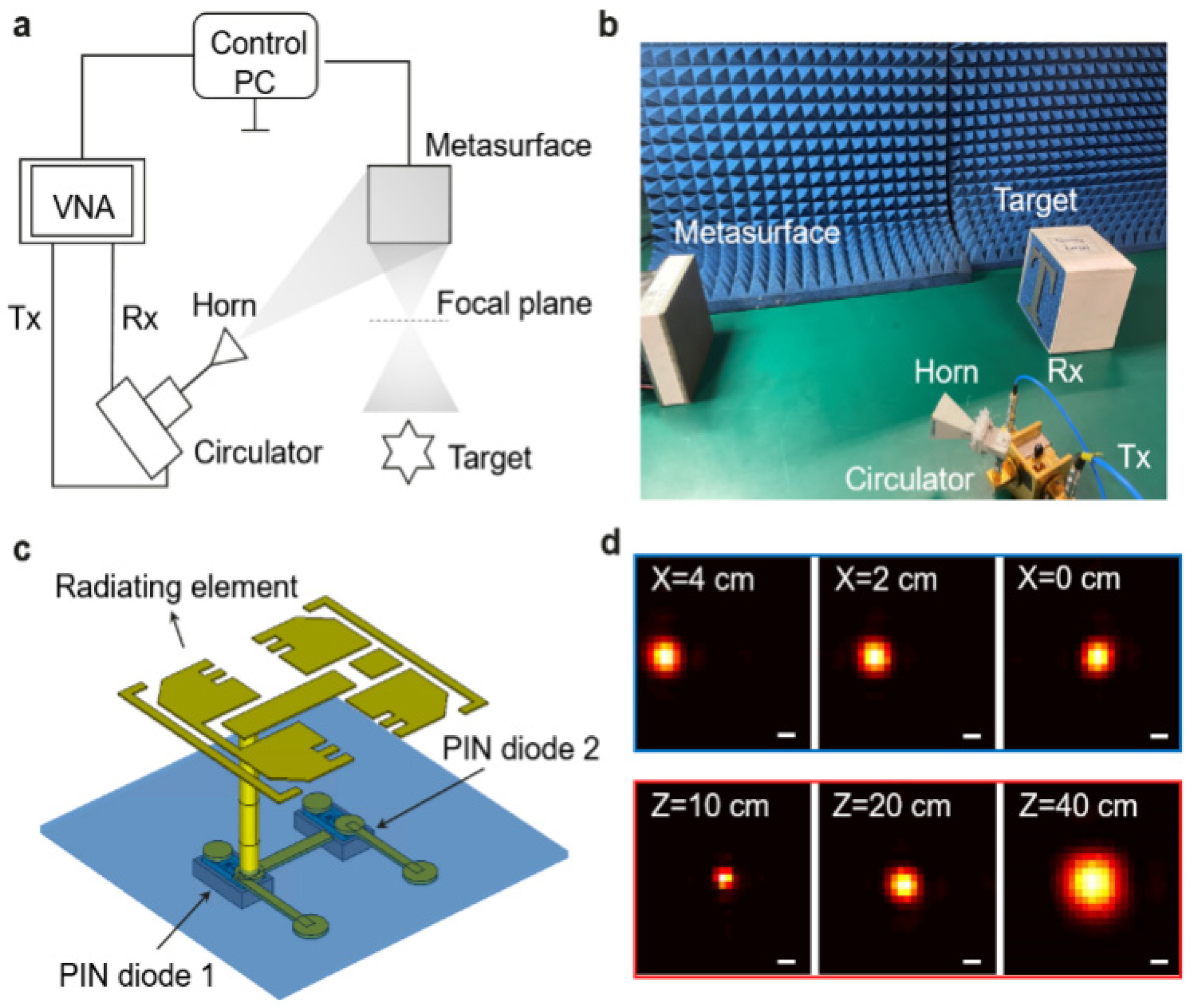
3.2. Experiment
4. Discussion
5. Conclusions
Author Contributions
Funding
Institutional Review Board Statement
Informed Consent Statement
Data Availability Statement
Conflicts of Interest
References
- Li, L.; Zhao, H.; Liu, C.; Li, L.; Cui, T.J. Intelligent metasurfaces: Control, communication and computing. Elight 2022, 2, 7. [Google Scholar] [CrossRef]
- Gollub, J.; Yurduseven, O.; Trofatter, K.P.; Arnitz, D.; Imani, M.F.; Sleasman, T.; Boyarsky, M.; Rose, A.; Pedross-Engel, A.; Odabasi, H. Large metasurface aperture for millimeter wave computational imaging at the human-scale. Sci. Rep. 2017, 7, 42650. [Google Scholar] [CrossRef] [PubMed]
- Yurduseven, O.; Fromenteze, T.; Decroze, C.; Fusco, V.F. Frequency-diverse computational automotive radar technique for debris detection. IEEE Sens. J. 2020, 20, 13167–13177. [Google Scholar] [CrossRef]
- Li, L.; Shuang, Y.; Ma, Q.; Li, H.; Zhao, H.; Wei, M.; Liu, C.; Hao, C.; Qiu, C.-W.; Cui, T.J. Intelligent metasurface imager and recognizer. Light Sci. Appl. 2019, 8, 97. [Google Scholar] [CrossRef]
- Shao, Y.; Su, Z.; He, H.; Jing, X.; Liu, Y.; Geng, G.; Li, J.; Wang, Y.; Huang, L. Multispectral imaging through metasurface with quasi-bound states in the continuum. Opt. Express 2024, 32, 23268–23279. [Google Scholar] [CrossRef]
- Cieślak, M.J.; Gamage, K.A.; Glover, R. Coded-aperture imaging systems: Past, present and future development—A review. Radiat. Meas. 2016, 92, 59–71. [Google Scholar] [CrossRef]
- Chan, W.L.; Charan, K.; Takhar, D.; Kelly, K.F.; Baraniuk, R.G.; Mittleman, D.M. A single-pixel terahertz imaging system based on compressed sensing. Appl. Phys. Lett. 2008, 93, 121105. [Google Scholar] [CrossRef]
- Shen, H.; Gan, L.; Newman, N.; Dong, Y.; Li, C.; Huang, Y.; Shen, Y. Spinning disk for compressive imaging. Opt. Lett. 2012, 37, 46–48. [Google Scholar] [CrossRef]
- Hunt, J.; Driscoll, T.; Mrozack, A.; Lipworth, G.; Reynolds, M.; Brady, D.; Smith, D.R. Metamaterial apertures for computational imaging. Science 2013, 339, 310–313. [Google Scholar] [CrossRef]
- Hunt, J.; Gollub, J.; Driscoll, T.; Lipworth, G.; Mrozack, A.; Reynolds, M.S.; Brady, D.J.; Smith, D.R. Metamaterial microwave holographic imaging system. JOSA A 2014, 31, 2109–2119. [Google Scholar] [CrossRef]
- Imani, M.F.; Sleasman, T.; Smith, D.R. Two-dimensional dynamic metasurface apertures for computational microwave imaging. IEEE Antennas Wirel. Propag. Lett. 2018, 17, 2299–2303. [Google Scholar] [CrossRef]
- Lan, G.; Imani, M.F.; Liu, Z.; Manjarrés, J.; Hu, W.; Lan, A.S.; Smith, D.R.; Gorlatova, M. MetaSense: Boosting RF sensing accuracy using dynamic metasurface antenna. IEEE Internet Things J. 2021, 8, 14110–14126. [Google Scholar] [CrossRef]
- Sleasman, T.; Boyarsky, M.; Pulido-Mancera, L.; Fromenteze, T.; Imani, M.F.; Reynolds, M.S.; Smith, D.R. Experimental synthetic aperture radar with dynamic metasurfaces. IEEE Trans. Antennas Propag. 2017, 65, 6864–6877. [Google Scholar] [CrossRef]
- Zhao, M.; Zhu, S.; Huang, H.; Hu, D.; Chen, X.; Chen, J.; Zhang, A. Frequency–Polarization Sensitive Metasurface Antenna for Coincidence Imaging. IEEE Antennas Wirel. Propag. Lett. 2021, 20, 1274–1278. [Google Scholar] [CrossRef]
- Zhu, S.; Dong, X.; He, Y.; Zhao, M.; Dong, G.; Chen, X.; Zhang, A. Frequency-polarization-diverse aperture for coincidence imaging. IEEE Microw. Wirel. Compon. Lett. 2017, 28, 82–84. [Google Scholar] [CrossRef]
- Watts, C.M.; Shrekenhamer, D.; Montoya, J.; Lipworth, G.; Hunt, J.; Sleasman, T.; Krishna, S.; Smith, D.R.; Padilla, W.J. Terahertz compressive imaging with metamaterial spatial light modulators. Nat. Photonics 2014, 8, 605–609. [Google Scholar] [CrossRef]
- Stantchev, R.I.; Sun, B.; Hornett, S.M.; Hobson, P.A.; Gibson, G.M.; Padgett, M.J.; Hendry, E. Noninvasive, near-field terahertz imaging of hidden objects using a single-pixel detector. Sci. Adv. 2016, 2, e1600190. [Google Scholar] [CrossRef]
- Stantchev, R.I.; Yu, X.; Blu, T.; Pickwell-MacPherson, E. Real-time terahertz imaging with a single-pixel detector. Nat. Commun. 2020, 11, 2535. [Google Scholar] [CrossRef]
- She, R.; Liu, W.; Lu, Y.; Zhou, Z.; Li, G. Fourier single-pixel imaging in the terahertz regime. Appl. Phys. Lett. 2019, 115, 021101. [Google Scholar] [CrossRef]
- He, Y.; Zhang, D.; Chen, Y. High-resolution wifi imaging with reconfigurable intelligent surfaces. IEEE Internet Things J. 2022, 10, 1775–1786. [Google Scholar] [CrossRef]
- Han, J.; Li, L.; Tian, S.; Liu, G.; Liu, H.; Shi, Y. Millimeter-wave imaging using 1-bit programmable metasurface: Simulation model, design, and experiment. IEEE J. Emerg. Sel. Top. Circuits Syst. 2020, 10, 52–61. [Google Scholar] [CrossRef]
- Datta, S.; Tamburrino, A.; Udpa, L. Gradient index metasurface lens for microwave imaging. Sensors 2022, 22, 8319. [Google Scholar] [CrossRef] [PubMed]
- Pulido-Mancera, L.; Fromenteze, T.; Sleasman, T.; Boyarsky, M.; Imani, M.F.; Reynolds, M.; Smith, D. Application of range migration algorithms to imaging with a dynamic metasurface antenna. JOSA B 2016, 33, 2082–2092. [Google Scholar] [CrossRef]
- Molaei, A.M.; Fromenteze, T.; Skouroliakou, V.; Hoang, T.V.; Kumar, R.; Fusco, V.; Yurduseven, O. Development of fast Fourier-compatible image reconstruction for 3D near-field bistatic microwave imaging with dynamic metasurface antennas. IEEE Trans. Veh. Technol. 2022, 71, 13077–13090. [Google Scholar] [CrossRef]
- Zhang, J.; Hu, T.; Shao, X.; Gu, H.; Xiao, Z. Wavenumber Spectrum Reconstruction Method for Microwave Computational Imaging with Re-Programmable Metasurface. IEEE Trans. Comput. Imaging 2023, 9, 383–395. [Google Scholar] [CrossRef]
- Molaei, A.M.; Fromenteze, T.; Hu, S.; Fusco, V.; Yurduseven, O. Fourier-based near-field three-dimensional image reconstruction in a multistatic imaging structure using dynamic metasurface antennas. IEEE Trans. Comput. Imaging 2022, 8, 1089–1100. [Google Scholar] [CrossRef]
- Skouroliakou, V.; Molaei, A.M.; Yurduseven, O. Towards real-time three-dimensional (3d) imaging using dynamic metasurface antennas. In Proceedings of the 2023 17th European Conference on Antennas and Propagation (EuCAP), Florence, Italy, 26–31 March 2023; pp. 1–5. [Google Scholar]
- Sheen, D.M.; McMakin, D.L.; Hall, T.E. Three-dimensional millimeter-wave imaging for concealed weapon detection. IEEE Trans. Microw. Theory Tech. 2001, 49, 1581–1592. [Google Scholar] [CrossRef]
- Ou, Z.; Wu, J.; Geng, H.; Deng, X.; Zheng, X. Confocal terahertz SAR imaging of hidden objects through rough-surface scattering. Opt. Express 2020, 28, 12405–12415. [Google Scholar] [CrossRef]
- Goodman, J.W. Introduction to Fourier Optics; Roberts and Company Publishers: Greenwood Village, CO, USA, 2005. [Google Scholar]
- Ralston, T.S.; Marks, D.L.; Scott Carney, P.; Boppart, S.A. Interferometric synthetic aperture microscopy. Nat. Phys. 2007, 3, 129–134. [Google Scholar] [CrossRef]
- Cooper, K.B.; Dengler, R.J.; Llombart, N.; Bryllert, T.; Chattopadhyay, G.; Schlecht, E.; Gill, J.; Lee, C.; Skalare, A.; Mehdi, I. Penetrating 3-D imaging at 4-and 25-m range using a submillimeter-wave radar. IEEE Trans. Microw. Theory Tech. 2008, 56, 2771–2778. [Google Scholar] [CrossRef]
- Grajal, J.; Badolato, A.; Rubio-Cidre, G.; Ubeda-Medina, L.; Mencia-Oliva, B.; Garcia-Pino, A.; Gonzalez-Valdes, B.; Rubinos, O. 3-D high-resolution imaging radar at 300 GHz with enhanced FoV. IEEE Trans. Microw. Theory Tech. 2015, 63, 1097–1107. [Google Scholar] [CrossRef]


| NBF | SVA | NBF | SVA | |
|---|---|---|---|---|
| (z = 30 cm) | (z = 40 cm) | |||
| letter “T” | 0.455 | 0.181 | 0.362 | 0.187 |
| letter “0” | 0.268 | 0.059 | 0.396 | 0.188 |
| Two batteries | 0.199 | 0.096 | 0.469 | 0.180 |
Disclaimer/Publisher’s Note: The statements, opinions and data contained in all publications are solely those of the individual author(s) and contributor(s) and not of MDPI and/or the editor(s). MDPI and/or the editor(s) disclaim responsibility for any injury to people or property resulting from any ideas, methods, instructions or products referred to in the content. |
© 2025 by the authors. Licensee MDPI, Basel, Switzerland. This article is an open access article distributed under the terms and conditions of the Creative Commons Attribution (CC BY) license (https://creativecommons.org/licenses/by/4.0/).
Share and Cite
Ou, Z.; Liang, Y.; Cai, H.; Wang, G. Three-Dimensional Scanning Virtual Aperture Imaging with Metasurface. Sensors 2025, 25, 280. https://doi.org/10.3390/s25010280
Ou Z, Liang Y, Cai H, Wang G. Three-Dimensional Scanning Virtual Aperture Imaging with Metasurface. Sensors. 2025; 25(1):280. https://doi.org/10.3390/s25010280
Chicago/Turabian StyleOu, Zhan, Yuan Liang, Hua Cai, and Guangjian Wang. 2025. "Three-Dimensional Scanning Virtual Aperture Imaging with Metasurface" Sensors 25, no. 1: 280. https://doi.org/10.3390/s25010280
APA StyleOu, Z., Liang, Y., Cai, H., & Wang, G. (2025). Three-Dimensional Scanning Virtual Aperture Imaging with Metasurface. Sensors, 25(1), 280. https://doi.org/10.3390/s25010280