
An Optical Wireless Communication System for Physiological Data Transmission in Small Animals

 , and
, and
Abstract
1. Introduction
2. Materials and Methods
2.1. Optical Wireless Communication System (OWCS)
2.2. Optical Tissue Phantoms (OTPs)
3. Results and Discussion

| Wavelength (nm) | Optical Power (mW) | Link Speed (Mbit/s) | Emitter Type | Receiver Type | Thickness (mm) | Free-Space (mm) | Ref. |
|---|---|---|---|---|---|---|---|
| 850 | 4.3 | 40 | VCSEL | Photodiode | 3 | - | [31] |
| 850 | 7.5 10 20 | 16 | VCSEL | Photodiode | 2 4 6 | - | [32] |
| 850 | 2.6 4.1 6.4 | 50 | VCSEL | Photodiode | 2 4 6 | - | [33] |
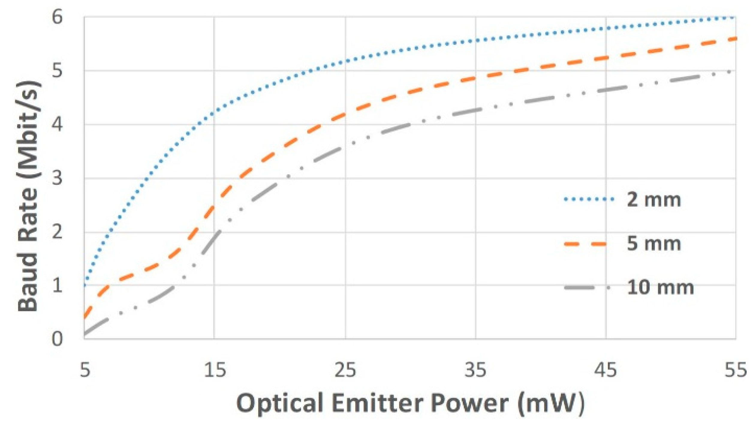
| 850 | 15 35 55 | 2 4.2 5 | LED | Photodiode | 10 | 50 | This work |
4. Conclusions
Author Contributions
Funding
Institutional Review Board Statement
Informed Consent Statement
Data Availability Statement
Acknowledgments
Conflicts of Interest
References
- Nelson, B.D.; Karipott, S.S.; Wang, Y.; Ong, K.G. Wireless Technologies for Implantable Devices. Sensors 2020, 20, 4604. [Google Scholar] [CrossRef]
- Niemeyer, J.E. Telemetry for Small Animal Physiology. Lab Anim. 2016, 45, 255–257. [Google Scholar] [CrossRef]
- Sohn, I.; Jang, Y.H.; Lee, S.H. Ultra-Low-Power Implantable Medical Devices: Optical Wireless Communication Approach. IEEE Commun. Mag. 2020, 58, 77–83. [Google Scholar] [CrossRef]
- Dias, N.S.; Carmo, J.P.; Mendes, P.M.; Correia, J.H. A Low-Power/Low-Voltage CMOS Wireless Interface at 5.7 GHz With Dry Electrodes for Cognitive Networks. IEEE Sens. J. 2011, 11, 755–762. [Google Scholar] [CrossRef]
- Carmo, J.P.; Correia, J.H. RF CMOS Transceiver at 2.4 GHz in Wearables for Measuring the Cardio-Respiratory Function. Measurement 2011, 44, 65–73. [Google Scholar] [CrossRef]
- Carmo, J.P.; Mendes, P.M.; Couto, C.; Correia, J.H. A 2.4-GHz CMOS Short-Range Wireless-Sensor-Network Interface for Automotive Applications. IEEE Trans. Ind. Electron. 2010, 57, 1764–1771. [Google Scholar] [CrossRef]
- Price, E.; Woodruff, D.P. Applications of the Shannon-Hartley Theorem to Data Streams and Sparse Recovery. In 2012 IEEE International Symposium on Information Theory Proceedings; IEEE: Piscataway, NJ, USA, 2012; pp. 2446–2450. [Google Scholar]
- FDA. Radio Frequency Wireless Technology in Medical Devices—Guidance for Industry and FDA Staff. 2013. Available online: https://www.fda.gov/regulatory-information/search-fda-guidance-documents/radio-frequency-wireless-technology-medical-devices-guidance-industry-and-fda-staff (accessed on 20 December 2024).
- ANSI. Safety Levels with Respect to Human Exposure to Radio Frequency Electromagnetic Fields, 300 kHz to 100 GHz. Available online: https://ehtrust.org/wp-content/uploads/2015/11/ANSI-National-standards-1982-safety-levels-for-human-exposure.pdf (accessed on 20 December 2024).
- Vizziello, A.; Magarini, M.; Savazzi, P.; Galluccio, L. Intra-Body Communications for Nervous System Applications: Current Technologies and Future Directions. Comput. Netw. 2023, 227, 109718. [Google Scholar] [CrossRef]
- Guillory, K.S.; Misener, A.K.; Pungor, A. Hybrid RF/IR Transcutaneous Telemetry for Power and High-Bandwidth Data. In Proceedings of the 26th Annual International Conference of the IEEE Engineering in Medicine and Biology Society, San Francisco, CA, USA, 1–5 September 2004; pp. 4338–4340. [Google Scholar]
- Aminoto, T.; Priambodo, P.S.; Sudibyo, H. Optical Imaging for Human Body Medical Analysis Using Polychromatic Infrared LED 700–1100 nm. The 4th Biomedical Engineering’s Recent Progress in Biomaterials, Drugs Development, Health, and Medical Devices. In Proceedings of the International Symposium of Biomedical Engineering, Padang, Indonesia, 22–24 July 2019; p. 050004. [Google Scholar]
- Kuniyil Ajith Singh, M.; Xia, W. Portable and Affordable Light Source-Based Photoacoustic Tomography. Sensors 2020, 20, 6173. [Google Scholar] [CrossRef] [PubMed]
- Cadence. Selecting a Photodiode Sensor for Infrared Optics. Available online: https://resources.pcb.cadence.com/blog/2020-selecting-a-photodiode-sensor-for-infrared-optics (accessed on 20 December 2024).
- Ackermann, D.M.; Smith, B.; Wang, X.-F.; Kilgore, K.L.; Peckham, P.H. Designing the Optical Interface of a Transcutaneous Optical Telemetry Link. IEEE Trans. Biomed. Eng. 2008, 55, 1365–1373. [Google Scholar] [CrossRef] [PubMed]
- Chuang, K.-C.; Ma, C.-C.; Liou, H.-C. Experimental Investigation of the Cross-Sensitivity and Size Effects of Polyvinylidene Fluoride Film Sensors on Modal Testing. Sensors 2012, 12, 16641–16659. [Google Scholar] [CrossRef] [PubMed]
- Liu, Z.; Li, S.; Zhu, J.; Mi, L.; Zheng, G. Fabrication of β-Phase-Enriched PVDF Sheets for Self-Powered Piezoelectric Sensing. ACS Appl. Mater. Interfaces 2022, 14, 11854–11863. [Google Scholar] [CrossRef]
- Rodrigues, J.A.; Pimenta, S.; Pereira, J.P.; Gomes, N.M.; Souto, M.R.; Fernandes, H.C.; Caetano, I.; Soares-Cunha, C.; Oliveira, J.F.; Ribeiro, J.F.; et al. Low-Cost Silicon Neural Probe: Fabrication, Electrochemical Characterization and in Vivo Validation. Microsyst. Technol. 2021, 27, 37–46. [Google Scholar] [CrossRef]
- Manimegalai, C.T.; Gauni, S.; Raghavan, N.; Rao, T.R. Investigations on Suitable Modulation Techniques for Visible Light Communications. In Proceedings of the International Conference on Wireless Communications, Signal Processing and Networking (WiSPNET), Chennai, India, 22–24 March 2017; pp. 1818–1822. [Google Scholar]
- Diodes Incorporated. ZVN3310FTA. Available online: https://www.diodes.com/assets/Datasheets/ZVN3310F.pdf (accessed on 20 December 2024).
- Vishay. VSLY5850. Available online: https://www.vishay.com/docs/83160/vsly5850.pdf (accessed on 20 December 2024).
- First Sensor. PS11.9-5 TO. Available online: https://pt.mouser.com/datasheet/2/418/9/fsens01139_1-3305134.pdf (accessed on 20 December 2024).
- Analog Devices. AD8015. Available online: https://www.analog.com/media/en/technical-documentation/data-sheets/AD8015.pdf (accessed on 20 December 2024).
- Analog Devices. AD8561. Available online: https://www.analog.com/media/en/technical-documentation/data-sheets/AD8561.pdf (accessed on 20 December 2024).
- Ntombela, L.; Adeleye, B.; Chetty, N. Low-Cost Fabrication of Optical Tissue Phantoms for Use in Biomedical Imaging. Heliyon 2020, 6, e03602. [Google Scholar] [CrossRef] [PubMed]
- Ayers, F.; Grant, A.; Kuo, D.; Cuccia, D.J.; Durkin, A.J. Fabrication and Characterization of Silicone-Based Tissue Phantoms with Tunable Optical Properties in the Visible and near Infrared Domain. In Proceedings of the SPIE BiOS, San Jose, CA, USA, 12 February 2008; p. 687007. [Google Scholar]
- Pogue, B.W.; Patterson, M.S. Review of Tissue Simulating Phantoms for Optical Spectroscopy, Imaging and Dosimetry. J. Biomed. Opt. 2006, 11, 041102. [Google Scholar] [CrossRef] [PubMed]
- Mahdy, A.; Deogun, J.S. Wireless Optical Communications: A Survey. In Proceedings of the IEEE Wireless Communications and Networking Conference (IEEE Cat. No.04TH8733), Atlanta, GA, USA, 21–25 March 2004; IEEE: Piscataway, NJ, USA, 2004; pp. 2399–2404. [Google Scholar]
- Slaiman, I.; Hamid, N.; Boon, T. Optical Wireless Communications Through Visible Light Leds: An Overview. Int. J. Eng. Res. Technol. IJERT 2014, 3, 1151–1156. [Google Scholar]
- Yeh, C.-H.; Yang, Y.-C.; Chow, C.-W.; Chen, Y.-W.; Hsu, T.-A. VCSEL and LED Based Visible Light Communication System by Applying Decode-and-Forward Relay Transmission. J. Light. Technol. 2020, 38, 5728–5732. [Google Scholar] [CrossRef]
- Ackermann, D.M. High Speed Transcutaneous Optical Telemetry Link. Master’s Thesis, Case Western Reserve University, Cleveland, OH, USA, 2007. [Google Scholar]
- Parmentier, S.; Fontaine, R.; Roy, Y. Laser Diode Used in 16 Mb/s, 10 MW Optical Transcutaneous Telemetry System. In Proceedings of the IEEE Biomedical Circuits and Systems Conference, Baltimore, MD, USA, 20–22 November 2008; pp. 377–380. [Google Scholar]
- Liu, T.; Bihr, U.; Anis, S.M.; Ortmanns, M. Optical Transcutaneous Link for Low Power, High Data Rate Telemetry. In Proceedings of the Annual International Conference of the IEEE Engineering in Medicine and Biology Society, San Diego, CA, USA, 28 August–1 September 2012; pp. 3535–3538. [Google Scholar]

| Wavelength (nm) | Material |
|---|---|
| 440–550 | InGaN |
| 570–650 | AlGaInP |
| 624–920 | AlGaAs |
Disclaimer/Publisher’s Note: The statements, opinions and data contained in all publications are solely those of the individual author(s) and contributor(s) and not of MDPI and/or the editor(s). MDPI and/or the editor(s) disclaim responsibility for any injury to people or property resulting from any ideas, methods, instructions or products referred to in the content. |
© 2024 by the authors. Licensee MDPI, Basel, Switzerland. This article is an open access article distributed under the terms and conditions of the Creative Commons Attribution (CC BY) license (https://creativecommons.org/licenses/by/4.0/).
Share and Cite
Domingues, A.R.; Pereira, D.; Silva, M.F.; Pimenta, S.; Correia, J.H. An Optical Wireless Communication System for Physiological Data Transmission in Small Animals. Sensors 2025, 25, 138. https://doi.org/10.3390/s25010138
Domingues AR, Pereira D, Silva MF, Pimenta S, Correia JH. An Optical Wireless Communication System for Physiological Data Transmission in Small Animals. Sensors. 2025; 25(1):138. https://doi.org/10.3390/s25010138
Chicago/Turabian StyleDomingues, Ana R., Diogo Pereira, Manuel F. Silva, Sara Pimenta, and José H. Correia. 2025. "An Optical Wireless Communication System for Physiological Data Transmission in Small Animals" Sensors 25, no. 1: 138. https://doi.org/10.3390/s25010138
APA StyleDomingues, A. R., Pereira, D., Silva, M. F., Pimenta, S., & Correia, J. H. (2025). An Optical Wireless Communication System for Physiological Data Transmission in Small Animals. Sensors, 25(1), 138. https://doi.org/10.3390/s25010138