
Portable Head-Mounted System for Mobile Forearm Tracking
 , , ,
, , ,  and
and 
Abstract
1. Introduction
2. Related Works
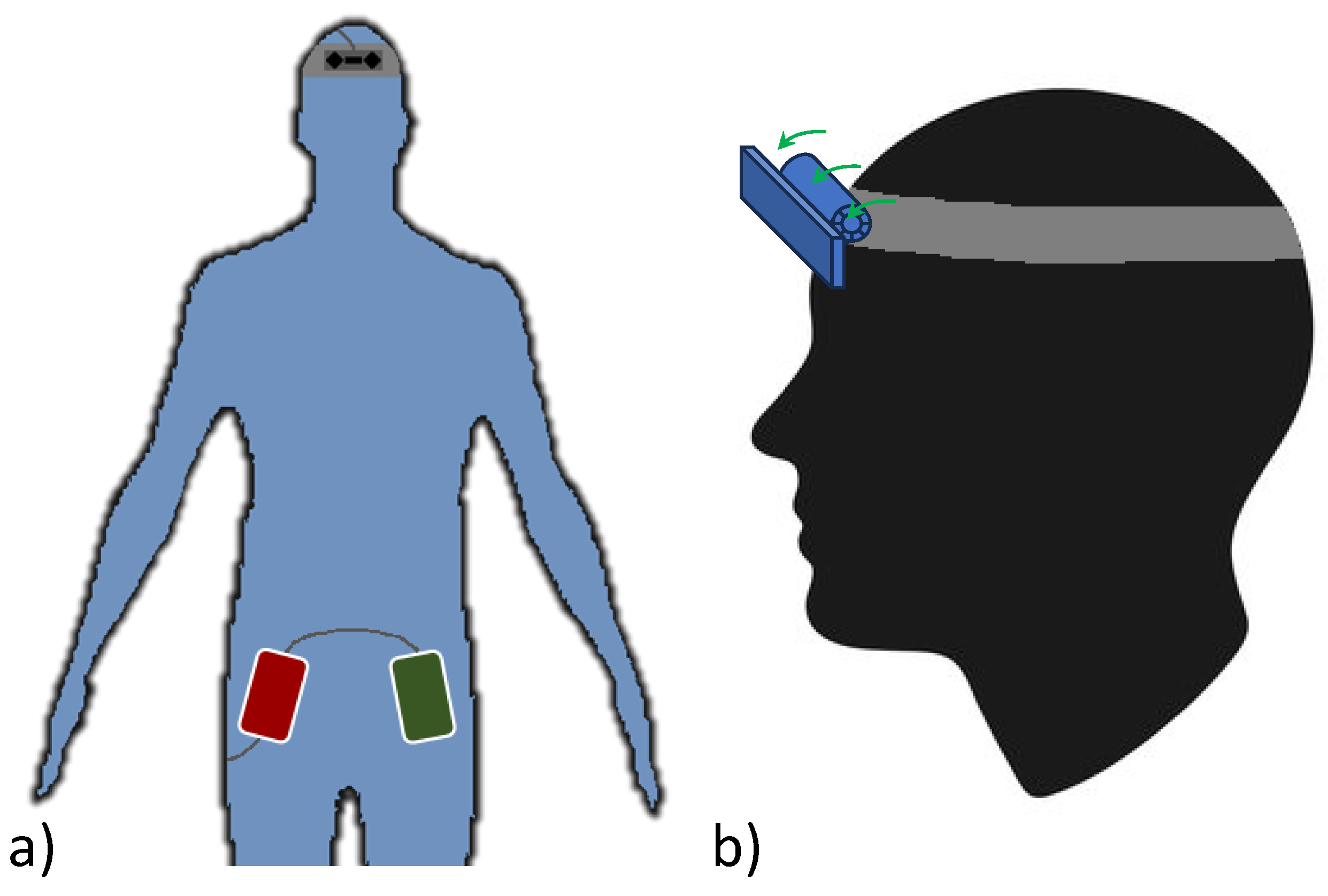
3. System Design
4. Measurements
- 1.
- RSP is on but without a connected LMC (RSP): The RSP is not actively involved in intensive operations or processes, consuming its lower-bound power and generating a lower-bound heat compared to when it is engaged in demanding tasks.
- 2.
- LMC is connected to RSP but not tracking (RSP + LMC): Compared to just the RSP, the LeapD daemon is running but data streaming is not requested by any software.
- 3.
- LMC is connected to RSP and data from forearm tracking is requested (RP + LMC + Data): Compared to the RSP + LMC task, a script for data acquisition, provided as an example by the LMC manufacturer, is running. The script requests data from the LeapD.
- 4.
- LMC is connected to the RSP, forearm tracking is running, and data are printed on the console (RP + LMC + Data + Print): Compared to the RP + LMC + Data task, the script is also printing data on the console. This configuration represents the worst-case (upper-bound) scenario for power consumption since, for the considered portable applications, the monitor is not used.
4.1. Power Consumption
4.2. CPU Usage and Temperature
4.3. Hand Tracking
5. Conclusions and Future Work
Author Contributions
Funding
Informed Consent Statement
Data Availability Statement
Conflicts of Interest
References
- Petracca, A.; Carrieri, M.; Avola, D.; Basso Moro, S.; Brigadoi, S.; Lancia, S.; Spezialetti, M.; Ferrari, M.; Quaresima, V.; Placidi, G. A virtual ball task driven by forearm movements for neuro-rehabilitation. In Proceedings of the 2015 International Conference on Virtual Rehabilitation (ICVR), Valencia, Spain, 9–12 June 2015; IEEE: Piscataway, NJ, USA, 2015. [Google Scholar] [CrossRef]
- Carrieri, M.; Petracca, A.; Lancia, S.; Basso Moro, S.; Brigadoi, S.; Spezialetti, M.; Ferrari, M.; Placidi, G.; Quaresima, V. Prefrontal Cortex Activation Upon a Demanding Virtual Hand-Controlled Task: A New Frontier for Neuroergonomics. Front. Hum. Neurosci. 2016, 10, 53. [Google Scholar] [CrossRef] [PubMed]
- Placidi, G.; Cinque, L.; Petracca, A.; Polsinelli, M.; Spezialetti, M. A Virtual Glove System for the Hand Rehabilitation based on Two Orthogonal LEAP Motion Controllers. In Proceedings of the 6th International Conference on Pattern Recognition Applications and Methods, Porto, Portugal, 24–26 February 2017. SCITEPRESS—Science and Technology Publications. [Google Scholar] [CrossRef]
- Theodoridou, E.; Cinque, L.; Mignosi, F.; Placidi, G.; Polsinelli, M.; Tavares, J.M.R.S.; Spezialetti, M. Hand Tracking and Gesture Recognition by Multiple Contactless Sensors: A Survey. IEEE Trans.-Hum.-Mach. Syst. 2023, 53, 35–43. [Google Scholar] [CrossRef]
- Hu, F.; He, P.; Xu, S.; Li, Y.; Zhang, C. FingerTrak: Continuous 3D hand pose tracking by deep learning hand silhouettes captured by miniature thermal cameras on wrist. Proc. ACM Interact. Mob. Wearable Ubiquitous Technol. 2020, 4, 1–24. [Google Scholar] [CrossRef]
- Masurovsky, A.; Chojecki, P.; Runde, D.; Lafci, M.; Przewozny, D.; Gaebler, M. Controller-Free Hand Tracking for Grab-and-Place Tasks in Immersive Virtual Reality: Design Elements and Their Empirical Study. Multimodal Technol. Interact. 2020, 4, 91. [Google Scholar] [CrossRef]
- Luong, T.; Cheng, Y.F.; Möbus, M.; Fender, A.; Holz, C. Controllers or Bare Hands? A Controlled Evaluation of Input Techniques on Interaction Performance and Exertion in Virtual Reality. IEEE Trans. Vis. Comput. Graph. 2023. [Google Scholar] [CrossRef] [PubMed]
- Sharif, H.; Eslaminia, A.; Chembrammel, P.; Kesavadas, T. Classification of activities of daily living based on grasp dynamics obtained from a leap motion controller. Sensors 2022, 22, 8273. [Google Scholar] [CrossRef] [PubMed]
- Viyanon, W.; Sasananan, S. Usability and performance of the leap motion controller and oculus rift for interior decoration. In Proceedings of the 2018 International Conference on Information and Computer Technologies (ICICT), DeKalb, IL, USA, 23–25 March 2018; IEEE: Piscataway, NJ, USA, 2018; pp. 47–51. [Google Scholar]
- Corrêa, A.G.D.; Kintschner, N.R.; Campos, V.Z.; Blascovi-Assis, S.M. Gear VR and leap motion sensor applied in virtual rehabilitation for manual function training: An opportunity for home rehabilitation. In Proceedings of the 5th Workshop on ICTs for improving Patients Rehabilitation Research Techniques, Lisbon, Portugal, 11–13 September 2019; pp. 148–151. [Google Scholar]
- Guzsvinecz, T.; Szucs, V.; Sik-Lanyi, C. Suitability of the Kinect sensor and Leap Motion controller—A literature review. Sensors 2019, 19, 1072. [Google Scholar] [CrossRef] [PubMed]
- Kincaid, C.; Johnson, P.; Charles, S.K. Feasibility of using the Leap Motion Controller to administer conventional motor tests: A proof-of-concept study. Biomed. Phys. Eng. Express 2023, 9, 035009. [Google Scholar] [CrossRef] [PubMed]
- Bachmann, D.; Weichert, F.; Rinkenauer, G. Evaluation of the leap motion controller as a new contact-free pointing device. Sensors 2014, 15, 214–233. [Google Scholar] [CrossRef]
- Hammer, J.H.; Beyerer, J. Robust hand tracking in realtime using a single head-mounted rgb camera. In Proceedings of the Human-Computer Interaction. Interaction Modalities and Techniques: 15th International Conference, HCI International 2013, Las Vegas, NV, USA, 21–26 July 2013; Proceedings, Part IV 15. Springer: Berlin/Heidelberg, Germany, 2013; pp. 252–261. [Google Scholar]
- Placidi, G.; Di Matteo, A.; Mignosi, F.; Polsinelli, M.; Spezialetti, M. Compact, Accurate and Low-cost Hand Tracking System based on LEAP Motion Controllers and Raspberry Pi. In Proceedings of the ICPRAM, Online, 3–5 February 2022; pp. 652–659. [Google Scholar]
- Sun, L.; Liu, G.; Liu, Y. 3D hand tracking with head mounted gaze-directed camera. IEEE Sen. J. 2013, 14, 1380–1390. [Google Scholar] [CrossRef]
- Akman, O.; Poelman, R.; Caarls, W.; Jonker, P. Multi-cue hand detection and tracking for a head-mounted augmented reality system. Mach. Vis. Appl. 2013, 24, 931–946. [Google Scholar] [CrossRef]
- Weichert, F.; Bachmann, D.; Rudak, B.; Fisseler, D. Analysis of the accuracy and robustness of the leap motion controller. Sensors 2013, 13, 6380–6393. [Google Scholar] [CrossRef] [PubMed]
- Placidi, G.; Cinque, L.; Polsinelli, M.; Spezialetti, M. Measurements by a LEAP-based virtual glove for the hand rehabilitation. Sensors 2018, 18, 834. [Google Scholar] [CrossRef] [PubMed]
- de Los Reyes-Guzmán, A.; Lozano-Berrio, V.; Alvarez-Rodriguez, M.; Lopez-Dolado, E.; Ceruelo-Abajo, S.; Talavera-Diaz, F.; Gil-Agudo, A. RehabHand: Oriented-tasks serious games for upper limb rehabilitation by using Leap Motion Controller and target population in spinal cord injury. NeuroRehabilitation 2021, 48, 365–373. [Google Scholar] [CrossRef] [PubMed]
- Martins, R.; Notargiacomo, P. Evaluation of leap motion controller effectiveness on 2D game environments using usability heuristics. Multimed. Tools Appl. 2021, 80, 5539–5557. [Google Scholar] [CrossRef]
- Fereidouni, S.; Sheikh Hassani, M.; Talebi, A.; Rezaie, A.H. A novel design and implementation of wheelchair navigation system using Leap Motion sensor. Disabil. Rehabil. Assist. Technol. 2022, 17, 442–448. [Google Scholar] [CrossRef] [PubMed]
- Ding, I.J.; Hsieh, M.C. A hand gesture action-based emotion recognition system by 3D image sensor information derived from Leap Motion sensors for the specific group with restlessness emotion problems. Microsyst. Technol. 2022, 28, 403–415. [Google Scholar] [CrossRef]
- Hisham, B.; Hamouda, A. Arabic sign language recognition using Ada-Boosting based on a leap motion controller. Int. J. Inf. Technol. 2021, 13, 1221–1234. [Google Scholar] [CrossRef]
- Lindsey, S. Evaluation of Low Cost Controllers for Mobile Based Virtual Reality Headsets. Master’s Thesis, Florida Institute of Technology, Melbourne, FL, USA, 2017. [Google Scholar]
- Moser, K.R.; Swan, J.E. Evaluation of user-centric optical see-through head-mounted display calibration using a leap motion controller. In Proceedings of the 2016 IEEE Symposium on 3D User Interfaces (3DUI), Greenville, SC, USA, 19–20 March 2016; IEEE: Piscataway, NJ, USA, 2016; pp. 159–167. [Google Scholar]
- Wright, T.; De Ribaupierre, S.; Eagleson, R. Design and evaluation of an augmented reality simulator using leap motion. Healthc. Technol. Lett. 2017, 4, 210–215. [Google Scholar] [CrossRef]
- Chien, P.H.; Lin, Y.C. Gesture-based head-mounted augmented reality game development using leap motion and usability evaluation. In Proceedings of the 15th International Conference on Interfaces and Human Computer Interaction, IHCI 2021 and 14th International Conference on Game and Entertainment Technologies, GET, Online, 21–23 July 2021; pp. 149–156. [Google Scholar]
- Zhang, H. Head-mounted display-based intuitive virtual reality training system for the mining industry. Int. J. Min. Sci. Technol. 2017, 27, 717–722. [Google Scholar] [CrossRef]
- Gusai, E.; Bassano, C.; Solari, F.; Chessa, M. Interaction in an immersive collaborative virtual reality environment: A comparison between leap motion and HTC controllers. In Proceedings of the New Trends in Image Analysis and Processing–ICIAP 2017: ICIAP International Workshops, WBICV, SSPandBE, 3AS, RGBD, NIVAR, IWBAAS, and MADiMa 2017, Catania, Italy, 11–15 September 2017; Revised Selected Papers 19. Springer: Berlin/Heidelberg, Germany, 2017; pp. 290–300. [Google Scholar]
- BELANOVÁ, D.; YOSHIDA, K. Hand Position Tracking Correction of Leap Motion Controller Attached to the Virtual Reality Headset. Int. J. Biomed. Soft Comput. Hum. Sci. Off. J. Biomed. Fuzzy Syst. Assoc. 2020, 25, 29–37. [Google Scholar]
- Microsoft Corporation. Microsoft HoloLens 2. 2024. Available online: https://www.microsoft.com/en-us/hololens (accessed on 10 January 2024).
- Zhang, S.; Ma, Q.; Zhang, Y.; Qian, Z.; Kwon, T.; Pollefeys, M.; Bogo, F.; Tang, S. Egobody: Human body shape and motion of interacting people from head-mounted devices. In Proceedings of the European Conference on Computer Vision, Tel Aviv, Israel, 23–27 October 2022; Springer: Berlin/Heidelberg, Germany, 2022; pp. 180–200. [Google Scholar]
- Doughty, M.; Ghugre, N.R. HMD-EgoPose: Head-mounted display-based egocentric marker-less tool and hand pose estimation for augmented surgical guidance. Int. J. Comput. Assist. Radiol. Surg. 2022, 17, 2253–2262. [Google Scholar] [CrossRef] [PubMed]
- Schäfer, A.; Reis, G.; Stricker, D. Controlling Continuous Locomotion in Virtual Reality with Bare Hands Using Hand Gestures. In Proceedings of the International Conference on Virtual Reality and Mixed Reality, Virtual, 26 June–1 July 2022; Springer: Berlin/Heidelberg, Germany, 2022; pp. 191–205. [Google Scholar]
- Abdlkarim, D.; Di Luca, M.; Aves, P.; Maaroufi, M.; Yeo, S.H.; Miall, R.C.; Holland, P.; Galea, J.M. A methodological framework to assess the accuracy of virtual reality hand-tracking systems: A case study with the Meta Quest 2. Behav. Res. Methods 2023, 1–12. [Google Scholar] [CrossRef] [PubMed]
- Meta Platforms, Inc. Meta Quest 3: New Mixed Reality VR Headset. 2024. Available online: https://www.meta.com/quest/quest-3/ (accessed on 10 January 2024).
- Challenor, J.; White, D.; Murphy, D. Hand-Controlled User Interfacing for Head-Mounted Augmented Reality Learning Environments. Multimodal Technol. Interact. 2023, 7, 55. [Google Scholar] [CrossRef]
- Raspberry Pi Ltd. Raspberry Pi Website. 2024. Available online: https://www.raspberrypi.org/ (accessed on 27 February 2024).
- Raspberry Pi and Python Users—We’ve Got News for You! Available online: https://www.reddit.com/r/Ultraleap/comments/181bohc/raspberry_pi_and_python_users_weve_got_news_for/ (accessed on 27 February 2024).
- Leap Motion Controller Software for Raspberry Pi. Available online: https://leap2.ultraleap.com/gemini-downloads/#tab-desktop (accessed on 27 February 2024).
- Leap Motion Controller 2 Datasheet. Available online: https://www.ultraleap.com/datasheets/leap-motion-controller-2-datasheet_issue13.pdf (accessed on 3 February 2024).
- The Operating Temperature For A Raspberry Pi. Available online: https://copperhilltech.com/content/The%20Operating%20Temperature%20For%20A%20Raspberry%20Pi%20%E2%80%93%20Technologist%20Tips.pdf (accessed on 3 February 2024).
- Qian, C.; Sun, X.; Wei, Y.; Tang, X.; Sun, J. Realtime and robust hand tracking from depth. In Proceedings of the IEEE Conference on Computer Vision and Pattern Recognition, Las Vegas, NA, USA, 27–30 June 2014; pp. 1106–1113. [Google Scholar]
- Roy, K.; Akif, M.A.H. Real time hand gesture based user friendly human computer interaction system. In Proceedings of the 2022 International Conference on Innovations in Science, Engineering and Technology (ICISET), Chattogram, Bangladesh, 25–28 February 2022; IEEE: Piscataway, NJ, USA, 2022; pp. 260–265. [Google Scholar]
- What is the Leap Motion Controller’s Operating Environment Range? Available online: https://support.ultraleap.com/hc/en-us/articles/360004328878-What-is-the-Leap-Motion-Controller-s-operating-environment-range (accessed on 2 March 2024).
- Placidi, G.; Di Matteo, A.; Lozzi, D.; Polsinelli, M.; Theodoridou, E. Patient–Therapist Cooperative Hand Telerehabilitation through a Novel Framework Involving the Virtual Glove System. Sensors 2023, 23, 3463. [Google Scholar] [CrossRef] [PubMed]
- Van der Lubbe, R.H.; Sobierajewicz, J.; Jongsma, M.L.; Verwey, W.B.; Przekoracka-Krawczyk, A. Frontal brain areas are more involved during motor imagery than during motor execution/preparation of a response sequence. Int. J. Psychophysiol. 2021, 164, 71–86. [Google Scholar] [CrossRef]
- Voigt-Antons, J.N.; Kojic, T.; Ali, D.; Möller, S. Influence of hand tracking as a way of interaction in virtual reality on user experience. In Proceedings of the 2020 Twelfth International Conference on Quality of Multimedia Experience (QoMEX), Athlone, Ireland, 26–28 May 2020; IEEE: Piscataway, NJ, USA, 2020; pp. 1–4. [Google Scholar]
- Li, J.; Liu, X.; Wang, Z.; Zhang, T.; Qiu, S.; Zhao, H.; Zhou, X.; Cai, H.; Ni, R.; Cangelosi, A. Real-time hand gesture tracking for human–computer interface based on multi-sensor data fusion. IEEE Sen. J. 2021, 21, 26642–26654. [Google Scholar] [CrossRef]
- Dayal, A.; Paluru, N.; Cenkeramaddi, L.R.; Yalavarthy, P.K. Design and implementation of deep learning based contactless authentication system using hand gestures. Electronics 2021, 10, 182. [Google Scholar] [CrossRef]


| Baseline Scenario (No Case, No Fan) | Operating Conditions (Inside a Case, Fan on) | |||||||
|---|---|---|---|---|---|---|---|---|
| RSP |
RSP + LMC |
RSP + LMC + Data |
RSP + LMC + Data + | RSP |
RSP + LMC |
RSP + LMC + Data |
RSP + LMC + Data + | |
| V | Avg: 5.05 Min: 5.04 Max: 5.06 | Avg: 5.01 Min: 5.00 Max: 5.02 | Avg: 5.00 Min: 4.99 Max: 5.01 | Avg: 5.06 Min: 5.05 Max: 5.06 | Avg: 5.05 Min: 5.03 Max: 5.06 | Avg: 5.03 Min: 5.02 Max: 5.04 | Avg: 4.97 Min: 4.96 Max: 4.98 | Avg: 4.98 Min: 4.97 Max: 5.01 |
| A | Avg: 0.53 Min: 0.50 Max: 0.62 | Avg: 0.84 Min: 0.79 Max: 0.95 | Avg: 1.19 Min: 1.15 Max: 1.29 | Avg: 1.30 Min: 1.26 Max: 1.36 | Avg: 0.58 Min: 0.55 Max: 0.65 | Avg: 1.03 Min: 1.00 Max: 1.08 | Avg: 1.37 Min: 1.30 Max: 1.45 | Avg: 1.38 Min: 1.32 Max: 1.48 |
| W | Avg: 2.68 Min: 2.55 Max: 3.15 | Avg: 4.19 Min: 3.95 Max: 4.75 | Avg: 5.97 Min: 5.75 Max: 6.47 | Avg: 6.55 Min: 6.34 Max: 6.85 | Avg: 2.91 Min: 2.80 Max: 3.29 | Avg: 5.20 Min: 5.02 Max: 5.42 | Avg: 6.81 Min: 6.49 Max: 7.20 | Avg: 6.85 Min: 6.62 Max: 7.39 |
| Baseline Scenario | Operating Conditions (Fan on) | |||||||
|---|---|---|---|---|---|---|---|---|
| RSP |
RSP + LMC |
RSP + LMC + Data |
RSP + LMC + Data + | RSP |
RSP + LMC |
RSP + LMC + Data |
RSP + LMC + Data + | |
| % | Avg: 0.14 Min: 0.00 Max: 1.30 | Avg: 10.63 Min: 9.80 Max: 11.60 | Avg: 74.02 Min: 72.80 Max: 75.10 | Avg: 74.57 Min: 68.10 Max: 79.50 | Avg: 0.10 Min: 0.00 Max: 0.70 | Avg: 10,67 Min: 9.30 Max: 18.40 | Avg: 73.95 Min: 72.70 Max: 74.90 | Avg: 74.09 Min: 73.00 Max: 75.20 |
| °C | Avg: 53.66 Min: 52.58 Max: 55.02 | Avg: 60.36 Min: 56.97 Max: 62.81 | Avg: 74.75 Min: 52.58 Max: 79.85 | Avg: 75.49 Min: 55.50 Max: 80.34 | Avg: 40.05 Min: 38.95 Max: 41.38 | Avg: 43.77 Min: 42.35 Max: 45.28 | Avg: 56.06 Min: 48.69 Max: 58.27 | Avg: 56.04 Min: 47.23 Max: 58.43 |
Disclaimer/Publisher’s Note: The statements, opinions and data contained in all publications are solely those of the individual author(s) and contributor(s) and not of MDPI and/or the editor(s). MDPI and/or the editor(s) disclaim responsibility for any injury to people or property resulting from any ideas, methods, instructions or products referred to in the content. |
© 2024 by the authors. Licensee MDPI, Basel, Switzerland. This article is an open access article distributed under the terms and conditions of the Creative Commons Attribution (CC BY) license (https://creativecommons.org/licenses/by/4.0/).
Share and Cite
Polsinelli, M.; Di Matteo, A.; Lozzi, D.; Mattei, E.; Mignosi, F.; Nazzicone, L.; Stornelli, V.; Placidi, G. Portable Head-Mounted System for Mobile Forearm Tracking. Sensors 2024, 24, 2227. https://doi.org/10.3390/s24072227
Polsinelli M, Di Matteo A, Lozzi D, Mattei E, Mignosi F, Nazzicone L, Stornelli V, Placidi G. Portable Head-Mounted System for Mobile Forearm Tracking. Sensors. 2024; 24(7):2227. https://doi.org/10.3390/s24072227
Chicago/Turabian StylePolsinelli, Matteo, Alessandro Di Matteo, Daniele Lozzi, Enrico Mattei, Filippo Mignosi, Lorenzo Nazzicone, Vincenzo Stornelli, and Giuseppe Placidi. 2024. "Portable Head-Mounted System for Mobile Forearm Tracking" Sensors 24, no. 7: 2227. https://doi.org/10.3390/s24072227
APA StylePolsinelli, M., Di Matteo, A., Lozzi, D., Mattei, E., Mignosi, F., Nazzicone, L., Stornelli, V., & Placidi, G. (2024). Portable Head-Mounted System for Mobile Forearm Tracking. Sensors, 24(7), 2227. https://doi.org/10.3390/s24072227