1. Introduction
Nowadays, local industrial networks are indispensable in application areas such as the machine building industry, building automation and construction, factory automation, aeronautics, energy distribution, industrial process control, etc. In general, industrial process automation is achieved using more sensors and execution elements, which at the same time leads to an increase in clocking systems in the production process. Connections between all equipment in the production process are made by means of connecting wires. Due to falling prices for process systems and rising prices for connecting wires, the time becomes clear for serial process control if input and output modules are located close to the sensors and adapters. Local industrial networks should be seen as an integrated part of automation processes and not as stand-alone solutions. Networks for the lowest levels of the automation hierarchy or so-called fieldbus systems have led to the increased flexibility and performance of automation systems. Given the large size of automation systems and installations, the benefits of fieldbus systems are clear. A more general definition for fieldbus is given by the Fieldbus Foundation as follows [
1]: fieldbus is a digital, bi-directional communication between intelligent measurement and control devices. It represents a local area network (LAN) for industrial process control, automation applications, etc. The Ethernet as a local area network (LAN) is becoming increasingly used in automation, but it seems that an industrial Ethernet does not make the fieldbus levels completely obsolete. Fieldbuses are better optimized for specific automation process attributes than general Ethernet networks. Fieldbus represents a step towards decentralization and increasing the quality of the control process [
2]. Also, other advantages of the fieldbus concept are its modularity, the possibility of expanding the installations and the ability to have intelligent devices that can communicate both for data transfer and maintenance and configuration [
3,
4]. A different design approach was to consider the network systems within the process control as columns of real-time distribution systems [
5]. As a result, the distinction between LAN (local area network) and FAN (field area network) should be based on the functionality and scope of these networks. So, FAN is a network used in automation processes regardless of the topology, protocol or real-time requirements.
The IIoT (Industrial Internet of Things) is usually used in manufacturing processes and refers to the industrial subset of the Internet.
In recent years, concerns in the field of industrial local area networks have grown so that a plethora of specifications and communication protocols have emerged, and the efforts of specialists in this field are focused on standardization and a reduction in the number of standards. In local area networks (LANs), the connection between intelligent sensors and execution elements is performed using communication protocols (Modbus, Profibus, CANOpen, Lonwork, MQTT, etc.).
Some protocols are simple and straightforward, while others are complex and require more sophisticated hardware resources. Modicon in 1979 made RS232 serial communication possible for PLCs produced by their company. The Modbus protocol is a unique protocol and is one of the most popular protocols among automation devices. In paper [
6], the authors present an original ModbusE extension, which is intended to extend the classical Modbus specification by introducing a time variable and, thus, transforming the Modbus protocol into a fully defined protocol. Unlike the Modbus classic, ModbusE defines an acquisition cycle (AC) that allows the periodic acquisition of values from the server stations at well-determined time intervals. Moreover, within the AC, the values transmitted on the ModbusE network can be seen as being in a publisher-subscriber architecture. In ModbusE, at the level of one slot, minus slots 0 and 1, messages can be sent that are fully compatible with Modbus classic. In the data area of a slot, specific messages can be sent to other protocols such as CANopen, PROFIBUS, etc. Using gateway servers, connections can be made with the resources at the ModbusE gateway level (such as Modbus TCP/IP, OPC UA), which allows the connection of messages from other protocols on the Internet (IIoT). The data area of the ModbusE message can be defined as carrying only the valuable part of classic Modbus messages, thus increasing the bandwidth of the communication channel. The data area of the ModbusE message can be used according to the application’s requirements. In paper [
7], the authors present a gateway based on Modbus/MQTT using Raspberry Pi that can be used in industrial cloud IoT applications. In paper [
8], the authors present a monitoring solution for smart buildings using OPC UA. In papers [
9,
10], the authors present the experiments and results obtained for the implementation of the acquisition cycle with ARM Cortex M0, M4 and M7 architectures. In paper [
11], the authors present a Modbus gateway for highly reliable communication where every controller can act as a master to start communication with devices on the virtual Modbus RTU network. In paper [
12], the authors present a controller using the STM32 microcontroller for a universal testing machine based on Modbus TCP. In Ref. [
13], the authors present MUbus as a SCADA protocol based on the Modbus protocol. In paper [
14], the authors present Modbus TCP and Modbus RTU to implement a double-layer monitoring network. In paper [
15], the authors describe an energy monitoring system based on the Modbus protocol and present the tests using 250 W and 500 W resistive loads.
The contributions made in this paper are the hardware and software architectures used to implement the ModbusE IIoT gateway on Sitara AM335x. The Sitara AM335x offers two real-time PRU cores that allow the implementation of the Modbus Extension and a Cortex A8 processor for the implementation of an OPC UA server, which is useful for IIoT applications. The present work presents a complete IIoT solution that, in addition to the ModbusE acquisition cycle, also presents an integrated OPC UA server on a single Sitara AM335x microcontroller (Texas Instruments (TI), Dallas, TX, USA) architecture. In the architectures previously made with ModusE, communication with the higher levels was performed with Modbus TCP/IP.
The remainder of this paper is organized as follows:
Section 2 describes the hardware and software architectures of the IIoT gateway.
Section 3 describes PRU0 (Programmable Real-Time Unit) performance.
Section 4 describes the communication channel modeling of the acquisition cycle.
Section 5 describes the flow of communication messages between the OPC UA client and IIoT gateway, and
Section 6 describes the performance analysis of the IIoT gateway data communications and the OPC UA client.
2. IIoT Gateway Hardware and Software Architectures and Networking
In paper [
10], the authors show that by using Cortex Mx architectures at a performance of approximately 49.6%, useful data from the acquisition cycle can be obtained with STM32F407 at a speed of 10.5 Mb/s on the serial port, with 36% useful data from the acquisition cycle with STM32F746 at a speed of 27 Mb/s on serial port and 58.9% useful data from AC with LPC4357 which has 2 Cortex M0 and Cortex M4 cores at 11.5 Mb speed/s on the serial port. In this paper, we started from the results obtained by the authors in paper [
10] and present a solution using the Sitara AM335x processor from Texas Instruments on the Beaglebone Black system. The presence of PRU (Programmable Real-Time Unit) processors leads to better performance on the physical channel data flow, and, at the same time, due to the ARM Cortex A8 processor, there is support for implementing IIoT connections based on OPC UA. As presented in paper [
16], the Sitara AM335x processor from Texas Instruments was chosen for the implementation of the IIoT gateway. The SitaraAm335x consists of a 32-bit ARM Cortex A8 RISC processor operating at a frequency of 1 GHz and two 32-bit PRU (Programmable Real-Time Unit) cores operating at a frequency of up to 200 MHz. One of the two PRU cores (PRU0) helped to improve data channel utilization, and the ARM Cortex A8 processor helped to provide a high-performance IIoT connection. The PRU core allows easy implementation of the ModbusE protocol at 12 Mb/s, while the ARM Cortex A8 processor with the Linux operating system supports the implementation of an OPC UA server with different middleware communication modes on the same system. The old versions with ARM Cortex Mx architectures used Modbus TCP/IP for Internet communication. So, the solution with Sitara AM335x is much more closely integrated by offering the OPC UA server. The solution on Sitara AM335x can also be used on other architectures, such as the one presented in this work [
17].
Figure 1 shows the main architecture of the experimental IIoT—ModbusE gateway system. The IIoT ModbusE Gateway module in
Figure 1 represents the master (client) station, also called the BSG (Base Station Gateway). This BSG implements the acquisition cycle (AC) at the PRU0 core, the OPC UA server and client application, as well as the dispatcher application at the ARM Cortex A8 processor. The OPC UA server and client application takes commands from an OPC UA client (running on a Windows operating system computer) via TCP/IP and forwards them to the dispatcher application. The dispatcher application takes commands from the OPC UA server and client application and sends them on to the purchasing cycle (CA). The dispatcher takes the response to commands from the acquisition cycle and sends it on to the OPC UA server and client application. The OPC UA server and client application, in turn, forward the response to the OPC UA client via TCP/IP. The IIoT ModbusE Server module in
Figure 1 represents the slave station (server), which was also implemented on the Sitara AM335x processor. This station takes data from sensors or sends commands to execution elements or actuators following commands from the BSG station. The other stations (ModbusE Server1, …, ModbusE Server n) represent other workstations using the ModbusE extension but are implemented with other technologies. The slave (server) stations communicate with the ModbusE Gateway IIoT module via serial ports using the RS485 serial line standard. The performance analysis of the IIoT—ModbusE Gateway experimental system is conducted for an acquisition cycle consisting of 10 slots.
3. PRU Performance
As presented in Chapter II of this paper, the PRU0 core on the Sitara AM335x processor was chosen to implement the Base Station Gateway (BSG) acquisition cycle (AC). This core is a Programmable Real-Time Unit (PRU) and operates at a frequency up to 200 MHz. Communication between the BSG station and the slave (server) stations is via the PRU UART serial port. The PRU UART port operates at speeds of up to 12 Mbps, so the duration of the 10-bit character to be processed is 0.83 microseconds. Measurements show that the duration of one bit at 12 Mbps is approximately 83.19 ns, and the period of one acquisition cycle with 10 slots is 1.349 ms. So, it follows that the maximum possible number of bits per acquisition cycle is 16,210 (1349 μs/0.08319 μs). Theoretically, a number of 1621 10-bit characters can be transmitted under continuous transmission conditions per the 10-slot acquisition cycle. But in reality, 1137 characters (3 + 4 + 20 + 40 + 80 + 96 + 510 + 128 + 128 + 128—see
Section 4 for more details) were transmitted per 10-slot acquisition cycle in the experimental system. This gives a total message (start address, start and stop bits, CRC checksum) of 70.1% (11370/16210 = 0.701). Subtracting the start address characters and the CRC checksum characters from the number of characters actually sent per acquisition cycle (with 10 slots transmitted and 8 slots received, as slot 0 and slot 1 do not receive characters) gives a total of 1082 characters per acquisition cycle and, thus, a useful message of 66.7% (1082/1621 = 0.667). A payload of 53.3% ((1082 × 8)/(1621 × 10) = 0.533) is obtained. The software application that implements the acquisition cycle on the PRU0 core (of the PRU-ICSS subsystem) for the master station (client) uses the status and control bits of the UART (Universal Asynchronous Receiver/Transmitter) and IEP (Industrial Ethernet Peripheral) peripheral ports. The IEP timer is used with the following two comparators: one comparator is used to determine the end of a message on reception, and the second comparator is used to signal the end of a slot duration. When the end of the slot duration is signaled, the comparator register is loaded with the duration of the next slot, and the RS485 driver is switched to transmit, after which the message transmission is started using the empty transmit register flag. During this time, the overflow indicator for the slot duration is also tested. If an overrun has occurred, the slot message transmission error is signaled, the driver is switched to receive, and the next slot is proceeded to. If the whole message has been sent, the driver is switched to receive and waits for the first character or overrun to be received for the slot duration, in which case a transmission error is signaled; the driver is switched to receive and moves to the next slot. If a character is received, the driver stays on receive until overrun is indicated for the end of the message on receive. Also, in this loop, the slot duration overrun indicator is tested, and the same actions as above are taken. Then, the driver switches to transmit and waits for the slot duration end indicator to pass before resuming the main loop with the next slot (slot_next = slot% NrMaxSlot). The software for the server (slave) station is implemented in a similar way, with the difference at the server (slave) level being the operation of moving the message from the receive buffer to where the application buffer occurs. When testing on the experimental system with a 10-slot acquisition cycle, the time durations for the slots are calculated mathematically. But, with these values for the slot durations, the acquisition cycle does not start working properly. For the acquisition cycle to start working properly, it is concluded that the slot durations should be adjusted with an adjustment time tAdjust. This tAdjust is determined empirically for each slot. It includes some communication times between the hardware components of the Sitara AM335x processor that are difficult to highlight and adjust. In the future, we foresee the creation of software for the automatic generation of these times. This tAdjust achieves the adjustment of the acquisition cycle so that it does not cause errors. The time period between transmission and reception for a slot with 510 characters, for example, depends on the processing times of the slave (server) stations, such as the time to calculate the CRC sum to check the correctness of the received message, the time to move the message from the reception buffer to the execution task buffer if the received request is to write to the slave, and the time needed to form the response if the received request is to read from the slave station. These times are more difficult to know and are retrieved in the tAdjust time. When the master station (client) receives the reply, a time for the CRC sum calculation occurs to check the integrity of the message received from the slave station.
4. Communication Channel Modeling of the Acquisition Cycle
The acquisition cycle within the ModbusE extension consists of slots. Each slot has a data structure with status, control and data information. The minimum number of slots in an acquisition cycle is three. The ModbusE extension uses the following two types of objects: the PDO (Process Data Object), which is used for process data transfer and the SDO (Service Data Object), used for configuration, maintenance and testing [
9,
18]. These objects (PDO and SDO) can be transported over the network using messages (multiple messages make up transactions). This ModbusE extension has three types of messages as follows: SDA (Send Data with Acknowledge), SDN (Send Data with No Acknowledge), and SRD (Send and Request Data) [
9,
18].
A frame consists of the following:
where f—frame and HT—header trailer.
A slot consists of the following:
We used an acquisition cycle with 10 slots.
NfAC—number of frames per acquisition cycle.
Max → 11,370 b/AC.
We used 1 bit at 12 Mb/s → 83.19 ns from the calculation at 83.33 ns.
The period of a 10-slot acquisition cycle is 1.349 ms
From the division,
resulting in a total message of 70.1% (with the start address, start and stop bits and the CRC count sum).
If the number of characters to be transmitted per 10 m slot acquisition cycle is reduced by the characters for the start address and checksum,
where 55 represents the characters for the start address and CRC checksum for 10 transmitted slots, and 8 received slots per acquisition cycle plus 1 control character for slot 1.
From the division,
resulting in a useful message of 66.7%.
From the formula,
resulting in a 53.3% payload (no start address, CRC checksum, start and stop bits or characters were included that were not useful data).
6. Performance Analysis of IIoT Gateway Data Communications, OPC UA Client (Windows)
In this chapter, we start with the analysis of the time required for the information requested by the OPC UA server (ServerOPCUAModBusE) running on the ARM Cortex A8 processor (under the Linux operating system) to traverse the following path: OPC UA server (ServerOPCUAModBusE)—dispatcher (BBB_ARM_A8_MBE_IOT_GATEWAY—also running on the ARM Cortex A8 processor)—acquisition cycle (with CA running on the PRU0 real-time kernel)—dispatcher—OPC UA server.
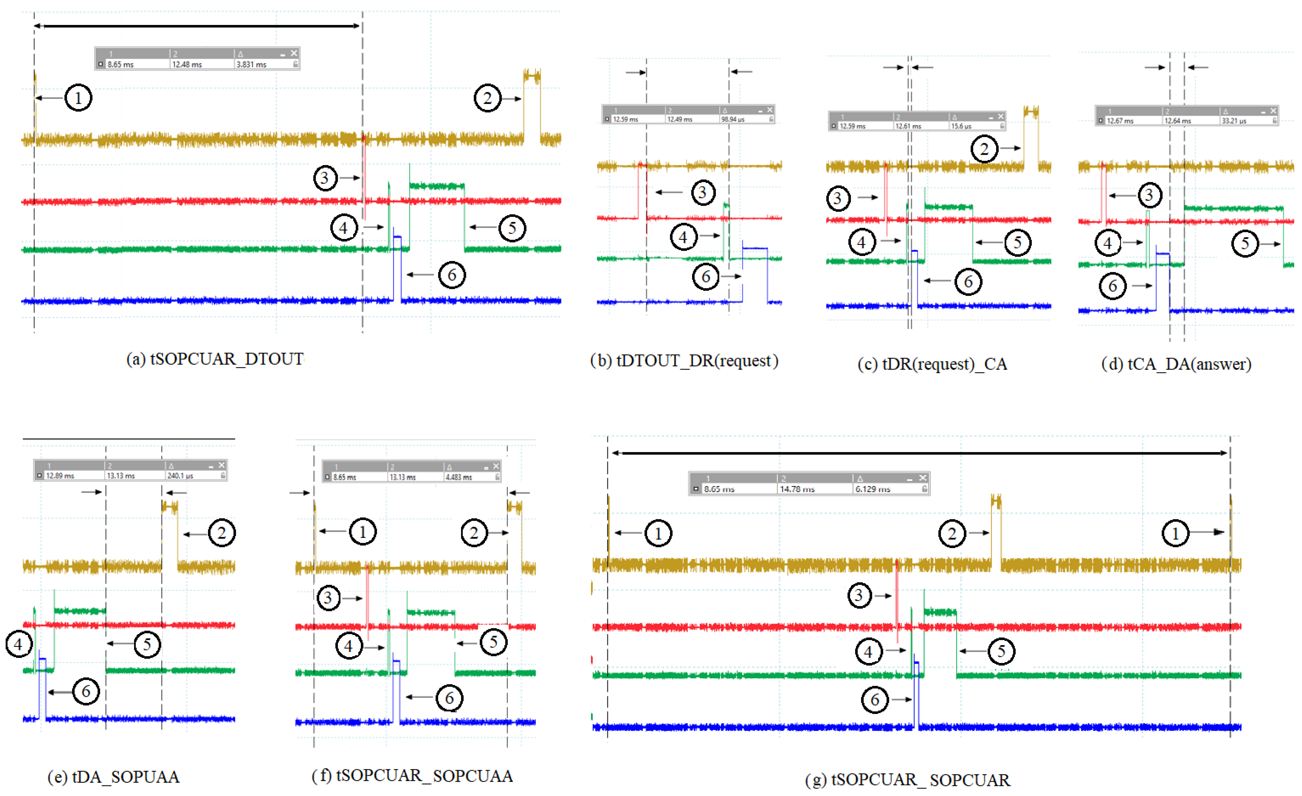
In
Figure 3, the numbered spikes represent the following: 1 represents the launch of the command by the OPC UA server running on the ARM Cortex A8 processor; 2 represents the response of the command received by the OPC UA server relaying on the ARM Cortex A8 processor; 3 represents the time when the dispatcher running on the ARM Cortex A8 processor tests if there is a command from the OPC UA server; 4 represents the time when the dispatcher sends the command to the acquisition cycle (CA—running on the PRU0 core); 5 represents the moment when the dispatcher (after the acquisition cycle has executed the received command) has finished the read or write operation in the shared data area (slot data without the acquisition cycle) and has reactivated the slot from which the command was sent; and 6 represents the moment when the request from the dispatcher is taken over by the acquisition cycle (CA) and the slot from which the request was sent is deactivated. The time tSOPCUAR_DTOUT (between spike 1 and spike 3) represents the time between the moment the OPC UA server (ServerOPCUAModBusE—running on the ARM Cortex A8 processor) sent the request to the dispatcher (BBB_ARM_A8_MBE_IOT_GATEWAY—running on the ARM Cortex A8 processor) and the moment the dispatcher tests for a request from the OPC UA server. The time tDTOUT_DR(request) [between spike 3 and spike 4] represents the time between the time the dispatcher tested if there was a request from the OPC UA server and the time it sent the request further to the acquisition cycle. The time tDR(request)_CA (between spike 4 and spike 6) is the length of time between when the dispatcher sent the request to the acquisition cycle (CA) and when the acquisition cycle retrieved the request from the dispatcher. The time tCA_DA(answer) [between spike 5 and spike 6] represents the time between the moment when the acquisition cycle retrieved the request from the dispatcher, deactivated the slot from which the request came in, executed the request and the moment when the dispatcher completed the read or write operation in the shared data area (the slot data of the acquisition cycle) and reactivated the slot from which the request was sent. The time tDA_SOPUAA (between spike 2 and spike 5) is the time between when the dispatcher, after preparing the response for the request, sent the response to the OPC UA server and the time when the OPC UA server retrieved the response from the dispatcher. The time tSOPCUAR_SOPCUAA (between spike 1 and spike 2) is the duration between the OPC UA server sending the request (command) to the dispatcher and the server receiving the request response from the dispatcher. Time tSOPCUAR_SOPCUAR (between spike 1 and spike 1) is the time between the OPC UA server launching a request to the dispatcher and the time the OPC UA server launches the next request to the dispatcher (the time between two consecutive requests).
Table 1 presents the values of the times shown above for 10 oscilloscope measurements.
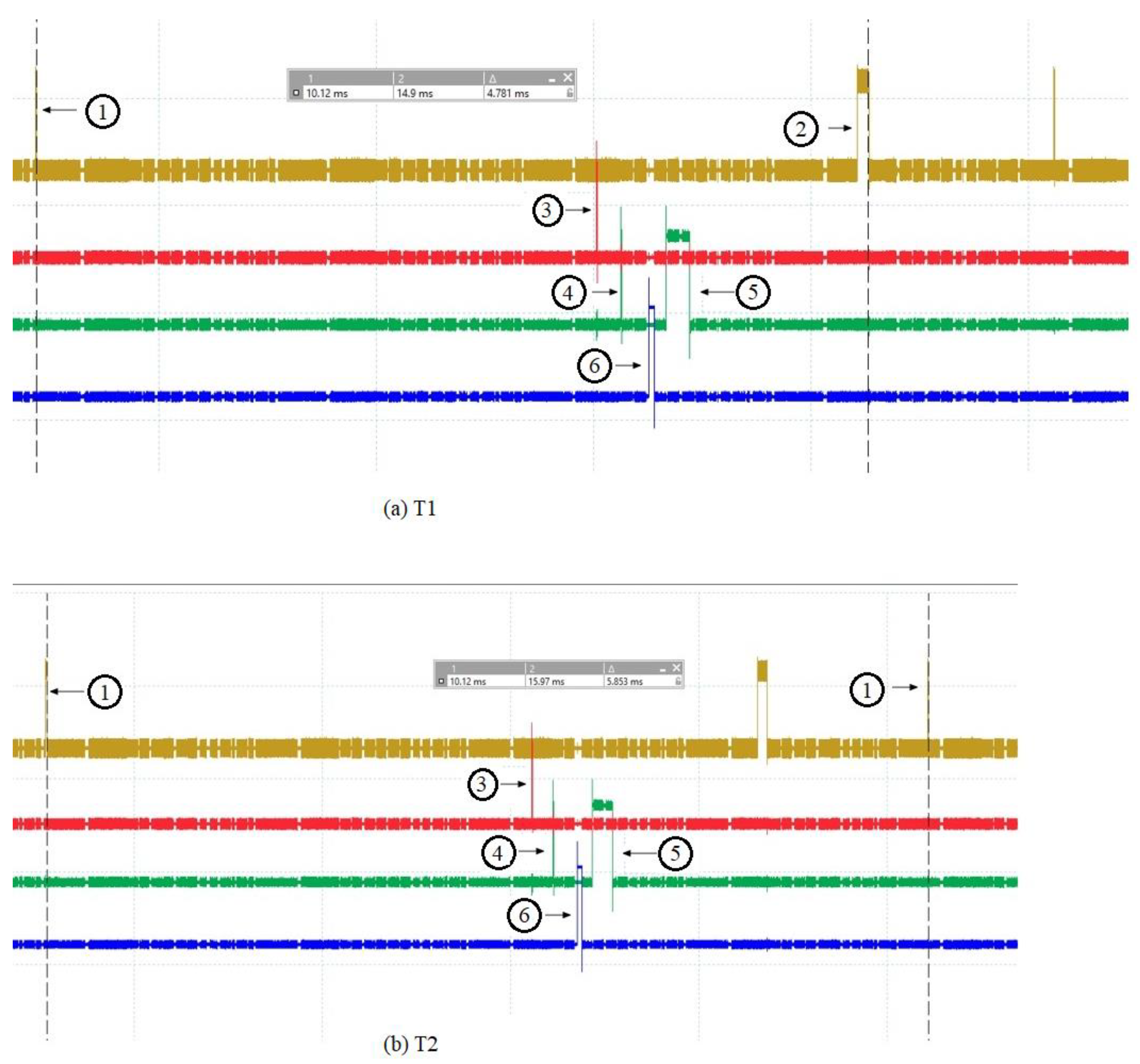
In
Figure 4, the numbered spikes represent the following: 1 represents when the OPC UA server (running on the ARM Cortex A8 processor) receives the request via sockets from the OPC UA client (running on a computer using the Windows operating system) and prepares to send it on via sockets to the dispatcher; 2 represents when the OPC UA server receives the request response from the dispatcher and the numbered spikes 3, 4, 5 and 6 are the same as in
Figure 3 and, therefore, are described in
Figure 3. Time T1 is the time between the OPC UA server preparing to forward the request from the OPC UA client to the dispatcher and the OPC UA server receiving the response from the dispatcher and preparing to forward it to the OPC UA client. Time T2 is the time between two consecutive requests that the OPC UA server prepares to make.
In
Table 2, the values for the times T1 and T2 described above are shown through 10 oscilloscope measurements.


