Article

A 19-Bit Small Absolute Matrix Encoder

Mechanical Engineering Faculty, Changchun University of Science and Technology, Changchun 130022, China
*
Author to whom correspondence should be addressed.
Sensors 2024, 24(5), 1400; https://doi.org/10.3390/s24051400
Submission received: 23 January 2024 / Revised: 15 February 2024 / Accepted: 19 February 2024 / Published: 22 February 2024
(This article belongs to the Special Issue Advanced Optical and Optomechanical Sensors)

Abstract

:
With the application of encoders in artificial intelligence and aerospace, the demand for the miniaturization and high measurement accuracy of encoders is increasing. To solve this problem, a new absolute matrix encoder is proposed in this paper, which can realize 19-bit matrix coding by engraving two circles of matrix code, and has the advantages of fewer circles of code disk engraving and higher measurement accuracy. This article mainly focuses on the design of a new matrix code disk, encoding and decoding methods, decoding circuit design, Matlab simulation analysis, and experimental error analysis. The experimental results show that the encoder designed in this paper achieves ultra-small volume Φ30 mm × 20 mm, and the angle measurement accuracy is 2.57”.

1. Introduction

A photoelectric encoder, also known as a photoelectric angle position sensor, is a digital angle measuring device that integrates light, machine and electricity. It is a sensor that converts the mechanical angular displacement into a pulse or digital quantity through photoelectric conversion [1,2,3]. Photoelectric encoders are widely used in many fields such as radar, photoelectric theodolite, CNC machine tool, robot and high-precision closed-loop speed control systems because of their high precision, fast response, non-contact measurement, anti-interference ability and stable performance [4,5].
With the development of aerospace and robotics technology in China, the miniaturization of absolute photoelectric encoders has been highly valued by enterprises and research institutes [6]. At present, the encoding methods for miniaturized absolute optoelectronic encoders mainly include Gray code, matrix code, single-ring Gray code, M-sequence code, and image encoding [7,8,9,10]. The matrix encoding method characterizes the encoding of different bits of traditional Gray codes on a circular code track, and its final output is the same as that of traditional Gray codes, but the number of code disk turns is reduced [11,12]. In 2010, Changchun Optical Machine Institute developed an eight-matrix absolute photoelectric encoder, which can realize 10-bit binary coding by engraving a two-circle matrix code track. In 2011, Changchun University of Science and Technology proposed a new matrix encoder solution, which realized 12-bit matrix coding by engraving two circles of matrix code; single-ring Gray code is a perfect encoding, but there are still many theoretical issues that need to be solved urgently [4,13]. Because the m-sequence code has no univariant, there are multi-bit changes between adjacent codes in use. In order to avoid coarse errors caused by code errors, the outer ring grating of the m-sequence code disk is the synchronous code track, and the inner ring is the m-sequence code [14,15]. When the encoder is designed with m-sequence code, multiple photosensitive probes need to be closely arranged. In order to realize the miniaturization of the encoder, an array charge-coupled device (CCD) is used to read the signal [16,17]. The introduction of an image sensor CCD increases the complexity of the light source and signal extraction, the resolution and accuracy of the measurement are more dependent on the quality of subsequent processing algorithms, and the complexity of the algorithms determines the response speed of the measurement device, ultimately restricting the maximum speed of the measured shaft [18,19,20].
By analyzing and summarizing the above encoding methods, the performance parameters of various encoders are compared in Table 1. The matrix Gray code encoding method of the optoelectronic encoder has the advantages of simple optomechanical structure, singularity, simple decoding, and high response rate compared to other encoding methods. However, there is a problem of insufficient accuracy in the case of a small number of code tracks.
This article proposes a new type of matrix encoder, which adopts a new method of code track engraving and encoding. The encoder only needs to engrave two circles of matrix code tracks to achieve 19-bit matrix encoding, achieving miniaturization of the encoder. Its volume is Φ30 mm × 20 mm, the encoder resolution reaches 19 bits, and the accuracy reaches 2.57”. At present, this encoder is a new type of encoder, which breaks through the limitations of traditional Gray codes and solves the contradiction between miniaturization and high measurement accuracy of encoders, meeting the requirements of aerospace, robotics, and nano-processing fields for encoders.

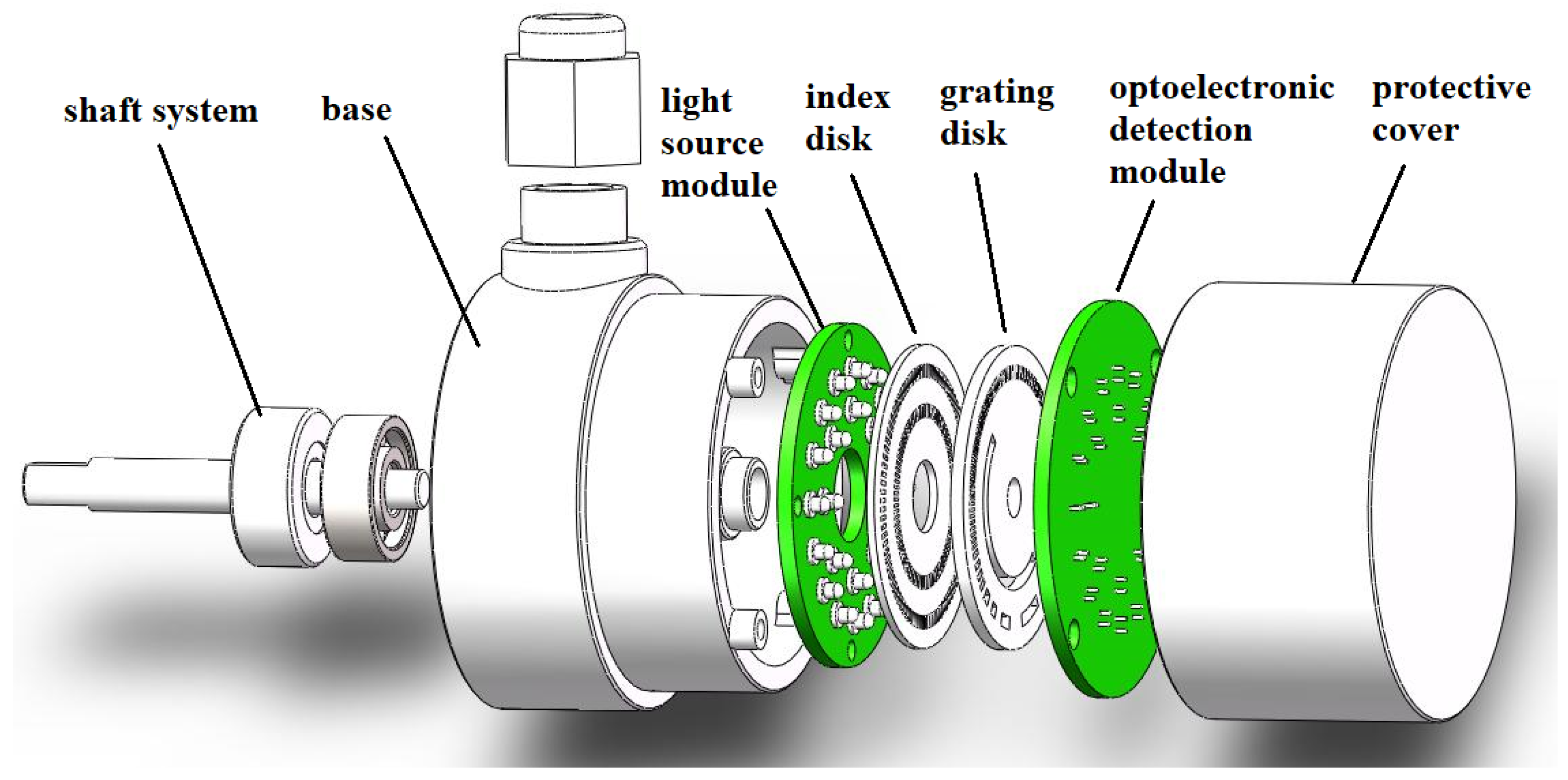
2. Working Principle

The exploded view of the matrix optoelectronic encoder proposed in this article is shown in Figure 1; it consists of a light source module, grating disk, index disk, optoelectronic detection module, shaft system, base, and protective cover. The light output by the LED light source module sequentially passes through the slit of the index disk and transparent area of the grating disk, and it is projected onto the opto-electronic receiver. The weak current signal output by the photoelectric receiver is amplified by a signal amplifier and a shaping circuit to output a square wave signal, and then decoded by a decoding circuit to output angle and position information.
As shown in Figure 1, when the encoder works, the grading disk rotates with the transmission shaft, and the LED light source module, photoelectric detection module and grading disk are stationary. Because of the obvious difference in the intensity of the optical signal received by the photoelectric detection module in the transparent area and the non-transparent area, we use binary codes “1” and “0” to represent the transparent area and the non-transparent area, respectively. By processing the binary code “1” and “0”, the decoding circuit converts the collected optical signal into an electrical signal that can be read by the machine for transmission and processing.

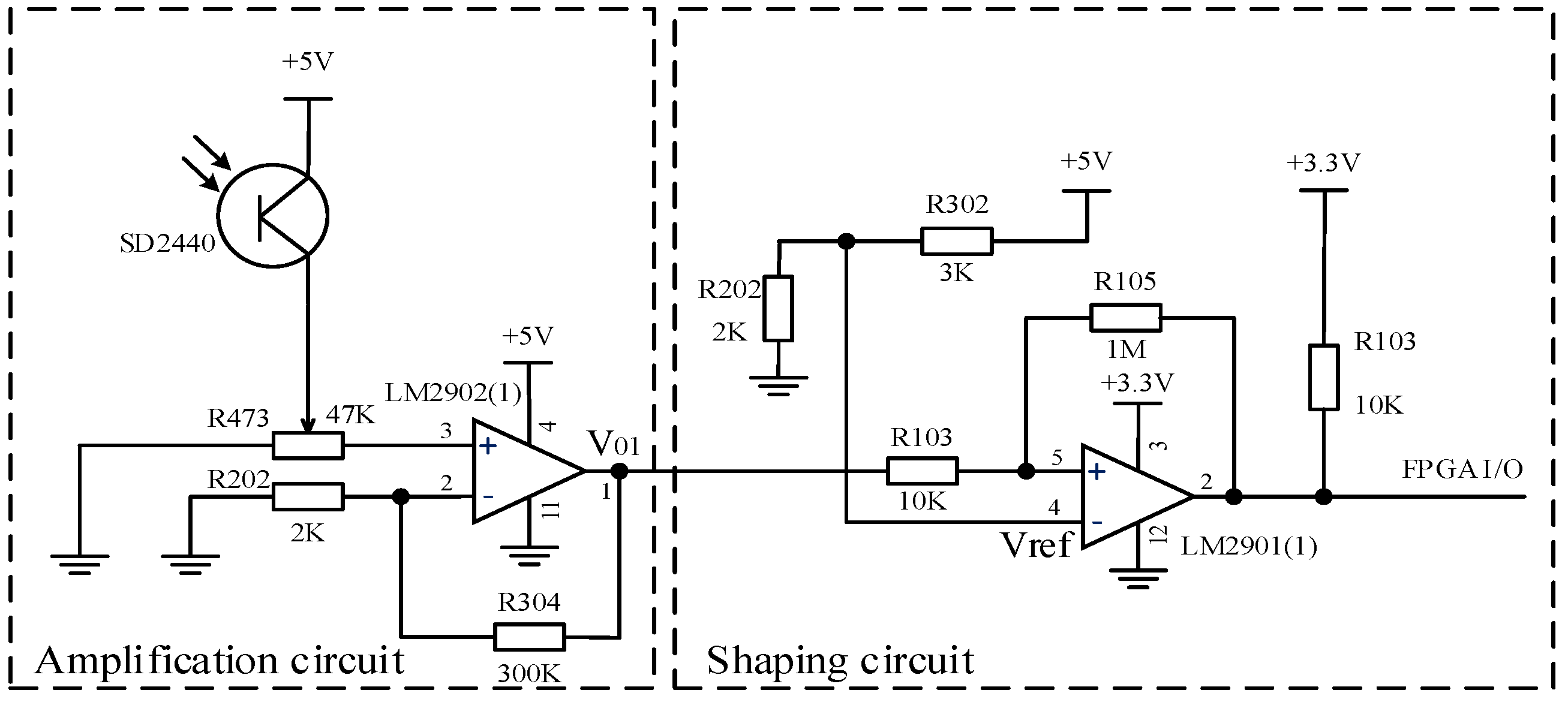
2.1. Design of Photoelectric Detection Circuit

Based on the advantages and disadvantages of different light sources and photodetectors, a selection was made. Considering that the encoder is an ultra small-volume encoder, Honeywell’s matching tubes, including SE2460 and SD2440, were selected in this paper to form the illumination and reception system. The main performance is shown in Table 2 and Table 3.
Due to the weak photoelectric current signal outputted by the photoelectric transistor, which cannot be directly read by the FPGA, we need to amplify and shape the current signal outputted by the photoelectric transistor to convert it into a square wave voltage signal. This article designs a photoelectric transistor amplification and shaping circuit as shown in Figure 2, which includes a voltage amplification circuit and a shaping circuit.
(1)
Voltage amplification circuit
The voltage amplification circuit uses a low-power integrated operational amplifier, LM2902, which is connected through voltage series negative feedback. As shown in Figure 2, the gain of the negative feedback voltage amplification circuit is:
A V = V 0 V i = A 1 + A F
Among them, A represents the gain of the basic amplification circuit, F represents the feedback coefficient of the feedback network, Vi represents the input voltage, V0 and represents the output voltage.
Because in the formula 1 + AF > >1, A V 1 F = 150 .
(2)
Shaping circuit
The shaping circuit converts the irregular voltage signal output by the voltage amplification circuit into a square wave. The voltage comparator compares the magnitude of two input voltages and outputs high and low levels based on the comparison results. The integrated voltage comparator chip LM2901 was selected, and positive feedback was introduced on the basis of the forward input single threshold voltage comparator to form a positive phase input hysteresis comparator with dual threshold values. It has strong anti-interference ability, and due to the acceleration of state transition by positive feedback, the edge of the output waveform is improved.

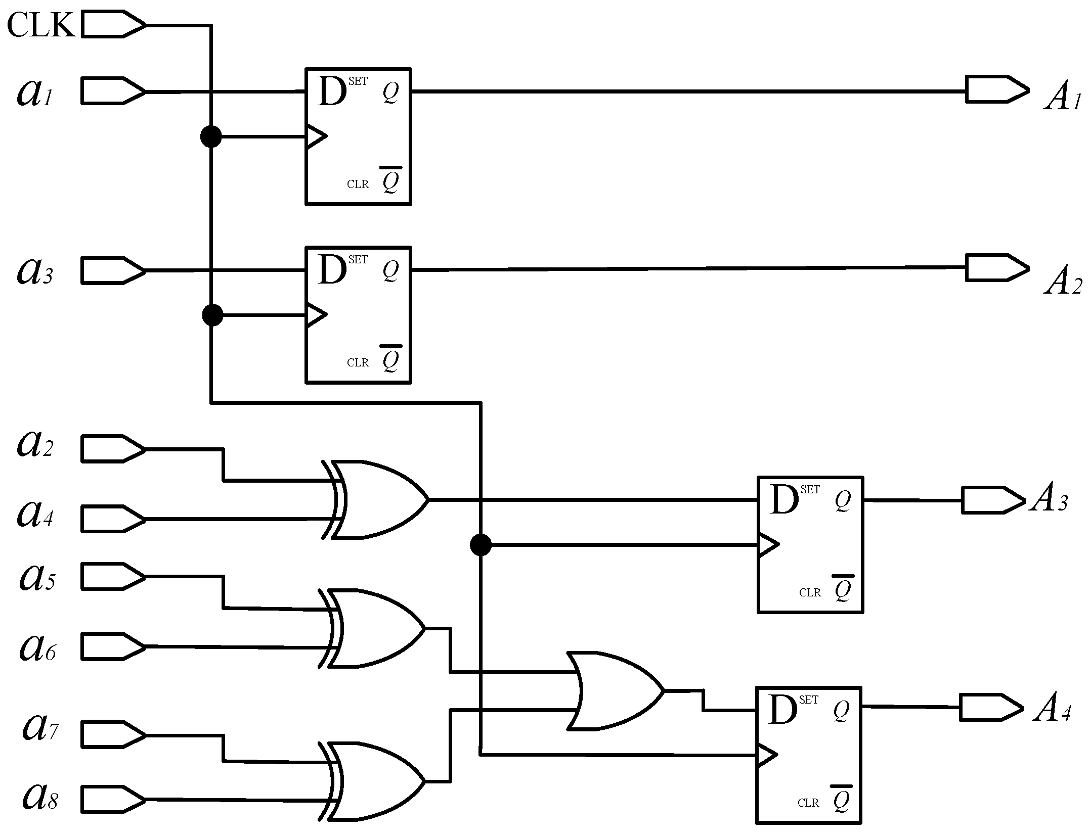
2.2. Design of Matrix Encoder

The traditional matrix encoder can read 8-bit binary codes by engraving three circles of matrix code, while the proposed 19-bit matrix encoder only needs to engrave two circles of code. As shown in Figure 3 and Figure 4, among them, 2n is the number of lines in each sector code area, and a1~a8 and b1~b16 are used to indicate the installation positions of the a and b ring photodetectors, respectively. The design of the inner circle code channel is the same as that of the traditional Gray code channel. By increasing the number of light sources and detectors to eight pairs, 4-bit traditional Gray code information can be read. The outer circle code track is evenly divided into sixteen code regions by slits, and sixteen optical probes are evenly distributed around the circumference to read fifteen bits of traditional Gray code information. This encoding method reduces the number of code disk circles while increasing the number of encoder encoding bits to nineteen bits.
The specific code track design of the matrix encoder is as follows:
The inner circle, namely circle a, is provided with a code track, which is the same as the traditional code track, with a light-passing area within half a cycle of 180°~360°.
The outer circle, namely circle b, can be divided into 16 code areas, engraving the 5th~19th bit of the traditional code track, and the center angle of each code area is 22.5°. Area 0°~22.5° is the 1st code area, engraving the 19th bit of the traditional code track, engraving 213 light-passing strips in the 22.5° circle range, called A19; 22.5°~45° is the 2nd code area, engraving the 18th bit of the traditional code track, engraving 212 light-passing strips in the 22.5° circle range, called A18; 45°~67.5° is the 3rd code area, engraving the 17th bit of the traditional code track, engraving 211 light-passing strips in the 22.5° circle range, called A17; 67.5°~90° is the 4th code area, engraving the 16th bit of the traditional code track, engraving 210 light-passing strips in the 22.5° circle range, called A16; 90°~112.5° is the 5th code area, engraving the 15th bit of the traditional code track, engraving 29 light-passing strips in the 22.5° circle range, called A15; 112.5°~135° is the 6th code area, engraving the 14th bit of the traditional code track, engraving 28 light-passing strips in the 22.5° circle range, called A14; 135°~157.5° is the 7th code area, engraving the 13th bit of the traditional code track, engraving 27 light-passing strips in the 22.5° circle range, called A13; 157.5°~180° is the 8th code area, engraving the 12th bit of the traditional code track, engraving 26 light-passing strips in the 22.5° circle range, called A12; 180°~202.5° is the 9th code area, engraving the 11th bit of the traditional code track, engraving 25 light-passing strips in the 22.5° circle range, called A11; 202.5°~225° is the 10th code area, engraving the 10th bit of the traditional code track, engraving 24 light-passing strips in the 22.5° circle range, called A10; 225°~247.5° is the 11th code area, engraving the 9th bit of the traditional code track, engraving 23 light-passing strips in the 22.5° circle range, called A9; 247.5°~270° is the 12th code area, engraving the 8th bit of the traditional code track, engraving 22 light-passing strips in the 22.5° circle range, called A8; 270°~292.5° is the 13th code area, engraving the 7th bit of the traditional code track, engraving 2 light-passing strips in the 22.5° circle range, called A7; 292.5°~315° is the 14th code area, engraving the 6th bit of the traditional code track, engraving 1 light-passing strip in the 22.5° circle range, called A6; and 315°~360° is the 15th and 16th code area, engraving the 5th bit of the traditional code track, engraving 1 light-passing strip in the 45° circle range, called A5.
From the distribution of code tracks, we can easily see that:
(1)
The circle a is exactly the same as the traditional Gray code track engraving method, which completes the encoding of 4-bit traditional code tracks through the placement of detectors.
(2)
The method of engraving each code track in each code area of circle b is consistent with traditional code tracks, and the center angle of the adjacent detectors in circle b is the same as the center angle occupied by each code area. Therefore, when the physical code disk is turned to any position, 16 detectors read each of the 16 code areas, ensuring that there is no dead angle recording of the code disk information within 360 °.

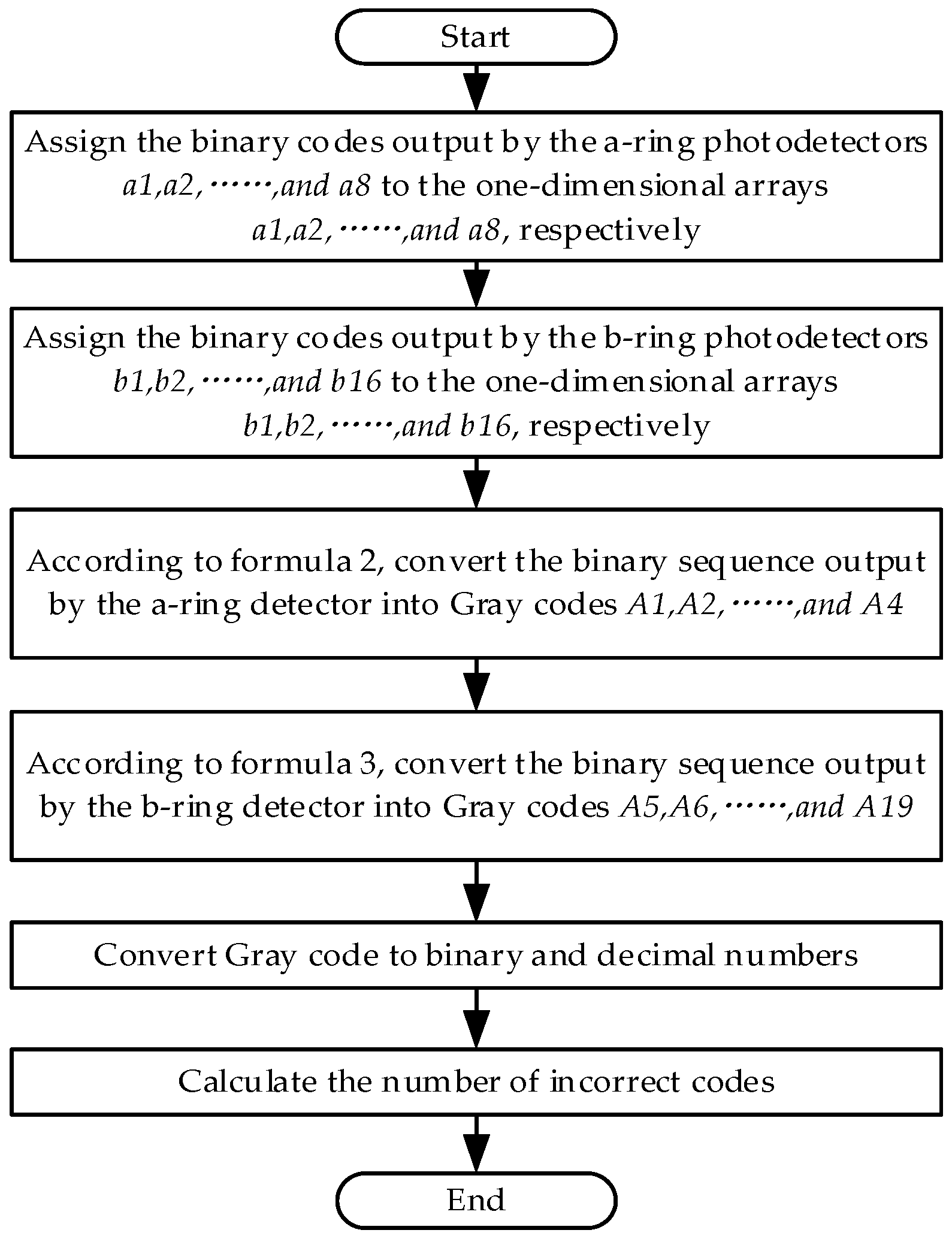
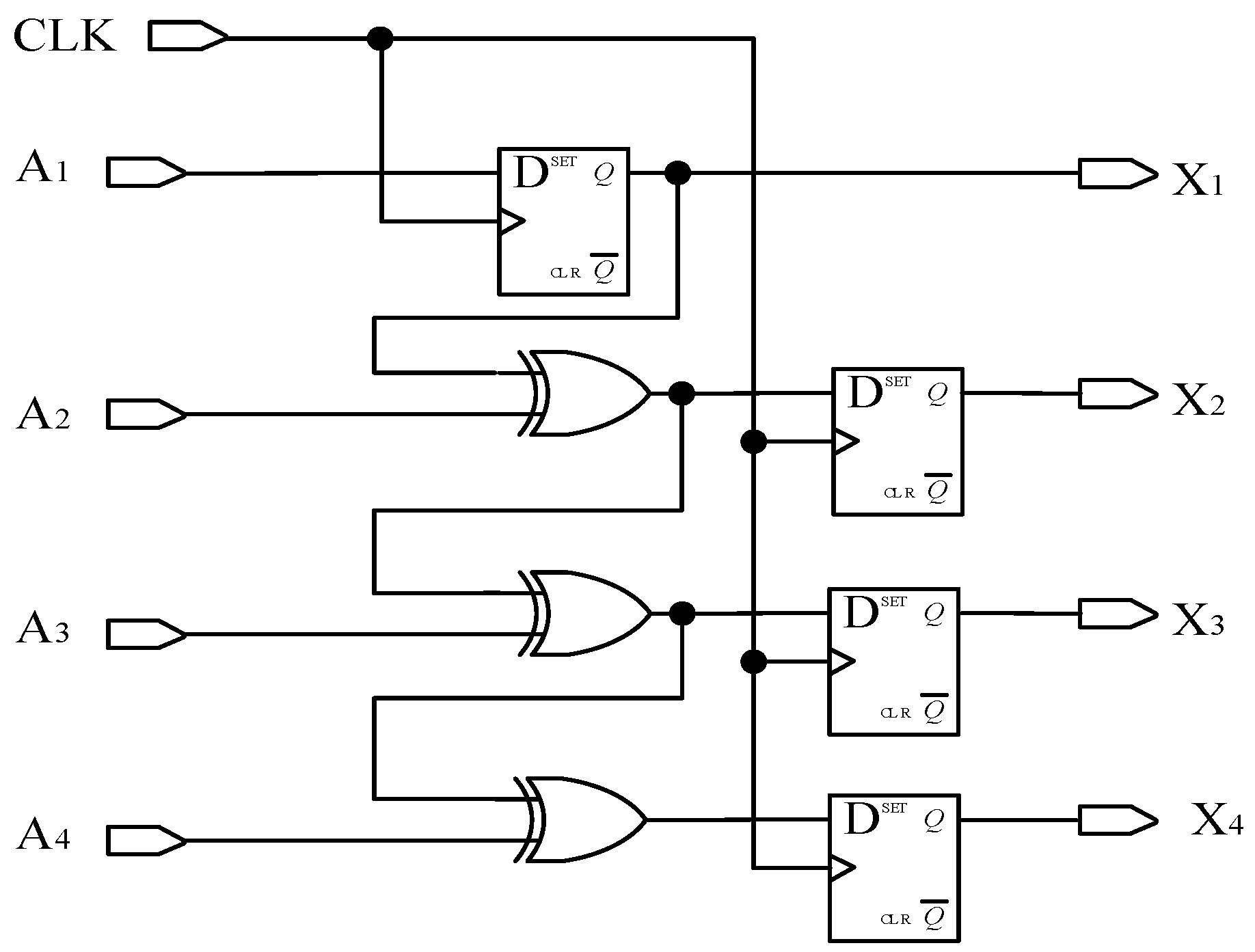
2.3. Decoding Principles

The traditional encoder circuit consists of amplification, shaping, temporary storage, and display components. This system adds a matrix decoding module on the basis of the traditional decoding circuit. The traditional circuit part will not be elaborated here, and this article mainly introduces the principle of matrix decoding. The so-called matrix decoding is for converting the code tracks arranged in a matrix manner into the same code tracks as the conventional code tracks. In order to improve the processing speed of the circuit and ensure the real-time output of the angle, this paper adopts a hardware circuit based on FPGA for the design of the decoding system.
From Figure 3, it can be seen that eight photo-detectors are placed on the a-ring code track to convert the optical signal into high- and low-level signals. The placement method of the a-ring detector is as follows: Eight detectors are evenly distributed along the circumference, detector a1 is placed at the 0° position, and a1 to a8 are placed counterclockwise in sequence.
The reading change of the a-ring detector within one cycle is shown in Figure 5; among them: the solid line represents high level, blank represents low level. The signals read by detectors a1 and a3, after amplification and shaping, are exactly the same as A1 and A2 encoded by traditional matrices; these two pulse signals serve as the first and second bit of the traditional Gray code. Therefore, the relationship between the eight signals ai in the first circle and the traditional Gray code Ai is as follows:
A 1 = a 1 A 2 = a 3 A 3 = a 2 a 4 A 4 = a 5 a 6 + a 7 a 8
On the b-ring code track, this paper proposes a scheme of sixteen quadrant matrix encoding, where sixteen detectors b1 to b16 are uniformly placed counterclockwise on a 360° circumference, with detector b1 placed at 0° and detector b16 placed at 337.5°.
When the encoder is turned to any position, each detector will read the light and dark stripes in different quadrants. When the encoder rotates clockwise, the relationship between the output pulse signal of each detector and the traditional Gray code is shown in Table 4. Taking the traditional Gray code A12 as an example, detector b1 reads this bit information in the 8th code area, and detector b2 reads this bit information in the 7th code area.
The b-ring code track is divided into 16 code areas, and each code area number i corresponds to the 4-bit Gray code of the a-ring. The corresponding relationship is shown in Table 5.
The conversion relationship between the signal bi read by the b-ring detector and the traditional Gray codes A5~A19 is represented by matrix Equation (3), where Mi represents the logical codes of code area i, such as: M 2 = A 1 ¯ A 2 ¯ A 3 ¯ A 4 .
A 5 A 6 A 7 A 8 A 9 A 10 A 11 A 12 A 13 A 14 A 15 A 16 A 17 A 18 A 19 = b 15 b 14 b 13 b 12 b 11 b 10 b 9 b 8 b 7 b 6 b 5 b 4 b 3 b 2 b 1 b 15 b 13 b 12 b 11 b 10 b 9 b 8 b 7 b 6 b 5 b 4 b 3 b 2 b 1 b 16 b 13 b 12 b 11 b 10 b 9 b 8 b 7 b 6 b 5 b 4 b 3 b 2 b 1 b 15 b 16 b 13 b 11 b 10 b 9 b 8 b 7 b 6 b 5 b 4 b 3 b 2 b 1 b 16 b 15 b 14 b 11 b 10 b 9 b 8 b 7 b 6 b 5 b 4 b 3 b 2 b 1 b 16 b 15 b 14 b 13 b 11 b 9 b 8 b 7 b 6 b 5 b 4 b 3 b 2 b 1 b 16 b 15 b 14 b 13 b 12 b 9 b 8 b 7 b 6 b 5 b 4 b 3 b 2 b 1 b 16 b 15 b 14 b 13 b 12 b 11 b 9 b 7 b 6 b 5 b 4 b 3 b 2 b 1 b 16 b 15 b 14 b 13 b 12 b 11 b 10 b 7 b 6 b 5 b 4 b 3 b 2 b 1 b 16 b 15 b 14 b 13 b 12 b 11 b 10 b 9 b 7 b 5 b 4 b 3 b 2 b 1 b 16 b 15 b 14 b 13 b 12 b 11 b 10 b 9 b 8 b 5 b 4 b 3 b 2 b 1 b 16 b 15 b 14 b 13 b 12 b 11 b 10 b 9 b 8 b 7 b 5 b 3 b 2 b 1 b 16 b 15 b 14 b 13 b 12 b 11 b 10 b 9 b 8 b 7 b 6 b 3 b 2 b 1 b 16 b 15 b 14 b 13 b 12 b 11 b 10 b 9 b 8 b 7 b 6 b 5 b 3 b 1 b 16 b 15 b 14 b 13 b 12 b 11 b 10 b 9 b 8 b 7 b 6 b 5 b 4 b 1 b 16 b 15 b 14 b 13 b 12 b 11 b 10 b 9 b 8 b 7 b 6 b 5 b 4 b 3 b 1 B 15 b 14 b 13 b 12 b 11 b 10 b 9 b 8 b 7 b 6 b 5 b 4 b 3 b 2 · M 1 M 2 M 3 M 4 M 5 M 6 M 7 M 8 M 9 M 10 M 11 M 12 M 13 M 14 M 15 M 16

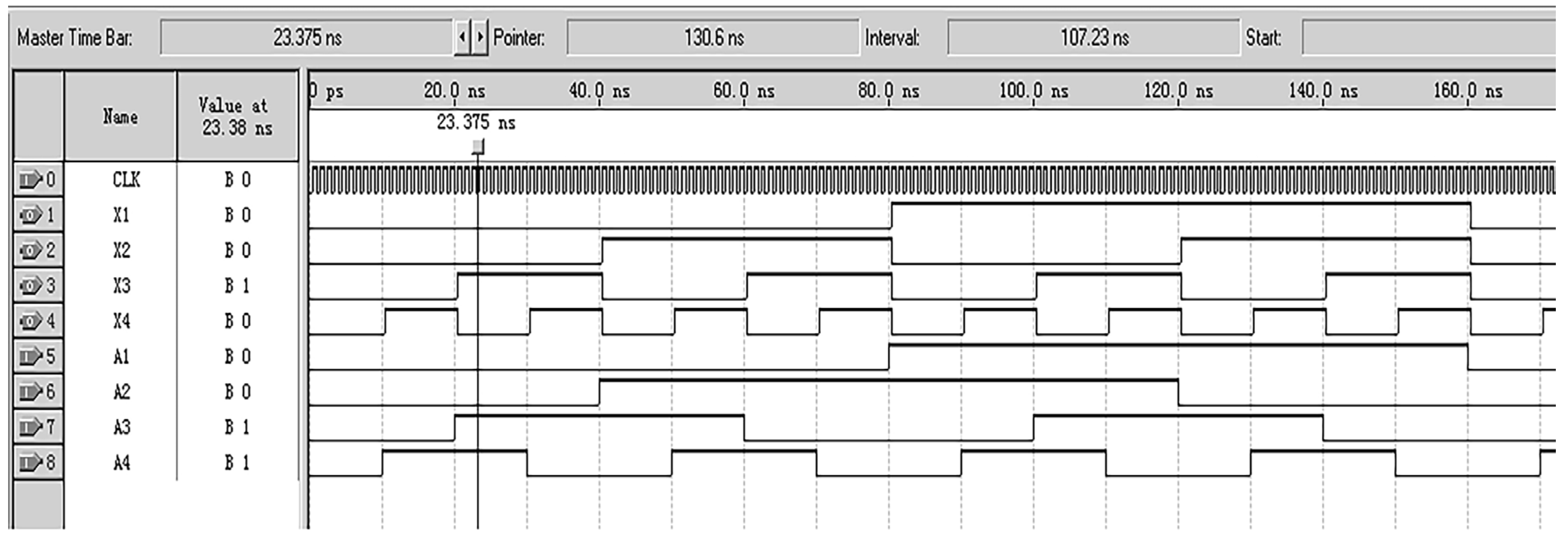
3. Simulation Analysis and Verification

Based on the method of matrix encoder encoding and decoding, the decoding part of the encoder was simulated using MATLAB R2021a software, and the simulation principle is shown in Figure 6. The design idea is to assign the high- and low-level signals read by the eight photodetectors a1~a8 in the circle a to the one-dimensional arrays a1~a8. Similarly, assign the high- and low-level signals outputted by the 16 photodetectors in circle b to the one-dimensional arrays b1~b16. Use Formulas (2) and (3) to calculate A1~A4 and A5~A19, respectively. Finally, convert the Gray code into binary and decimal numbers, and calculate the number of errors. The simulation results prove that the number of error codes is zero, so the encoding and decoding methods used in this design are feasible.
In order to ensure the high-speed and real-time performance of the decoding circuit, this paper adopts a digital decoding circuit based on FPGA for high-speed decoding. The Gray code used in this paper is matrix encoded, and the entire decoding process can be divided into two parts: matrix Gray code → traditional Gray code → binary code.
(1)
Matrix decoding
According to Formula (2), the decoding circuit for converting an a-ring code track to a traditional Gray code is shown in Figure 7, where the D flip-flop has two inputs, clock CLK and data D. And, the D flip-flop has two outputs: one is the main output, represented by Q, and the other is the reverse level of Q represented by Q ¯ . When no clock input is applied to the D flip-flop or during the falling edge of the clock signal, the output Q remains unchanged from its previous value. If the clock signal is on the rising edge, the output Q remains consistent with the input D. CLK is the system clock, used to control the sampling frequency and synchronization of the system; a1, a2, …, and a8 are the level signals read by photo-detectors a1, a2,…, and a8, respectively; and A1, A2, A3, and A4 represent the traditional Gray code.
Due to the fact that the encoder designed in this article requires a large number of logical units and a fast running speed, Altera’s Cyclone series FPGA chip EP1C3T144C8 was selected, with the configuration chip EPC2. This FPGA chip has a dedicated global clock pin, and FPGA global clock resources are generally implemented using all copper layer technology. A dedicated clock buffer and driver structure were designed to allow the global clock to reach all configurable units inside the chip. The crystal oscillator selected is the small-sized programmable oscillator SIT8002UT chip from the SITIME company. Functional and timing simulations were conducted on the decoding module using Quartus II 9.0 software, and the results are shown in Figure 8. From the figure, it can be seen that the decoder starts working at the rising edge of the system clock CLK, and the simulation results are consistent with theoretical calculations. The decoding method and process of the b-ring code track are similar to the above. Due to the length of the article, this article only discusses the decoding implementation of the a-ring code track.
(2)
Traditional Gray code → Natural binary code
According to the rule of converting Gray code into natural binary code, the highest bit of Gray code is retained as the highest bit of binary code. According to the equation X i = A I X i 1 , calculate the remaining bits of a binary number. This article designs a decoding circuit, as shown in Figure 9, and conducts functional simulation, as shown in Figure 10. The traditional Gray code is converted into commonly used natural binary codes, where A1, A2, A3, and A4 are traditional Gray codes, and X1, X2, X3, and X4 are natural binary codes.

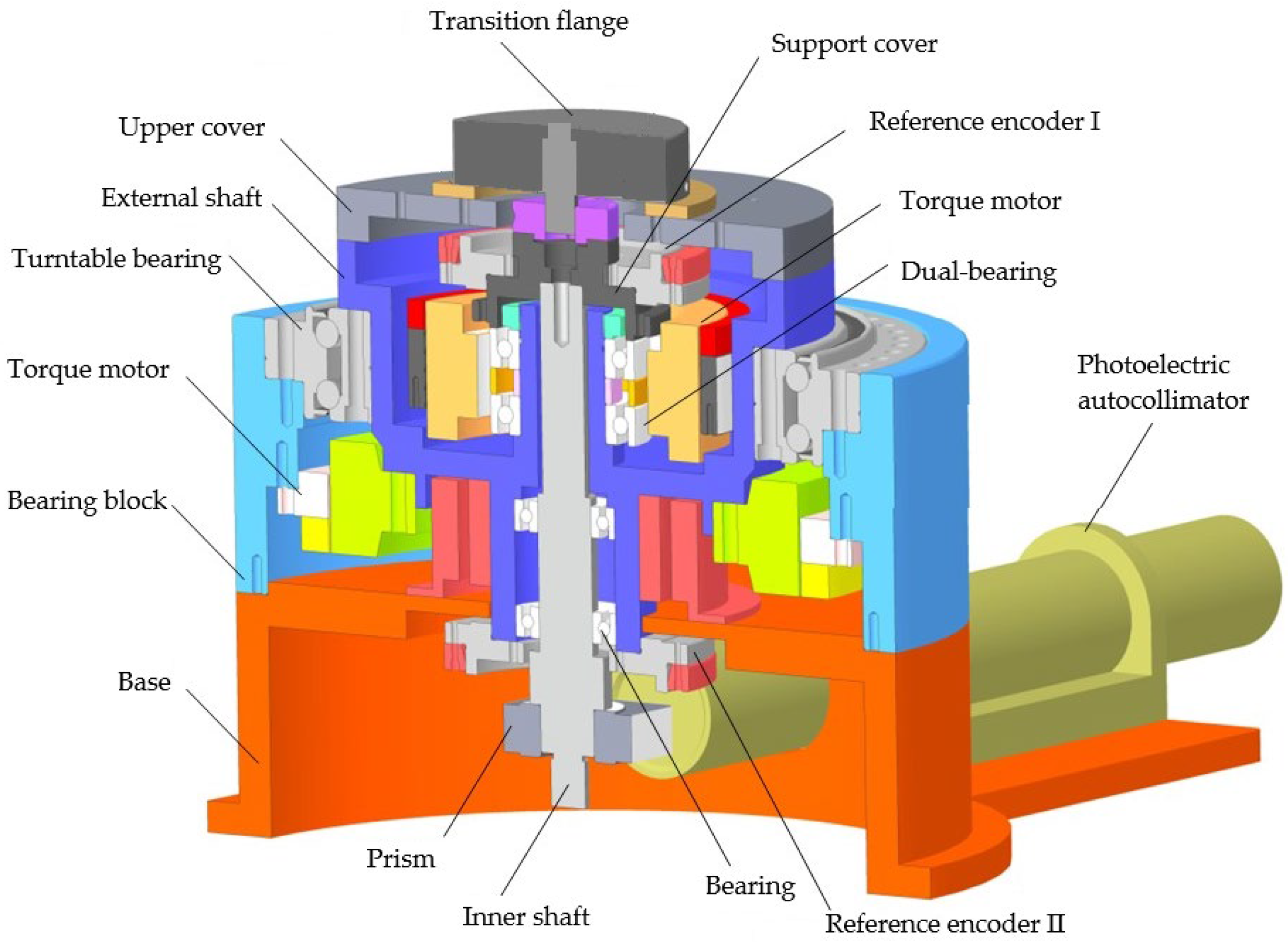
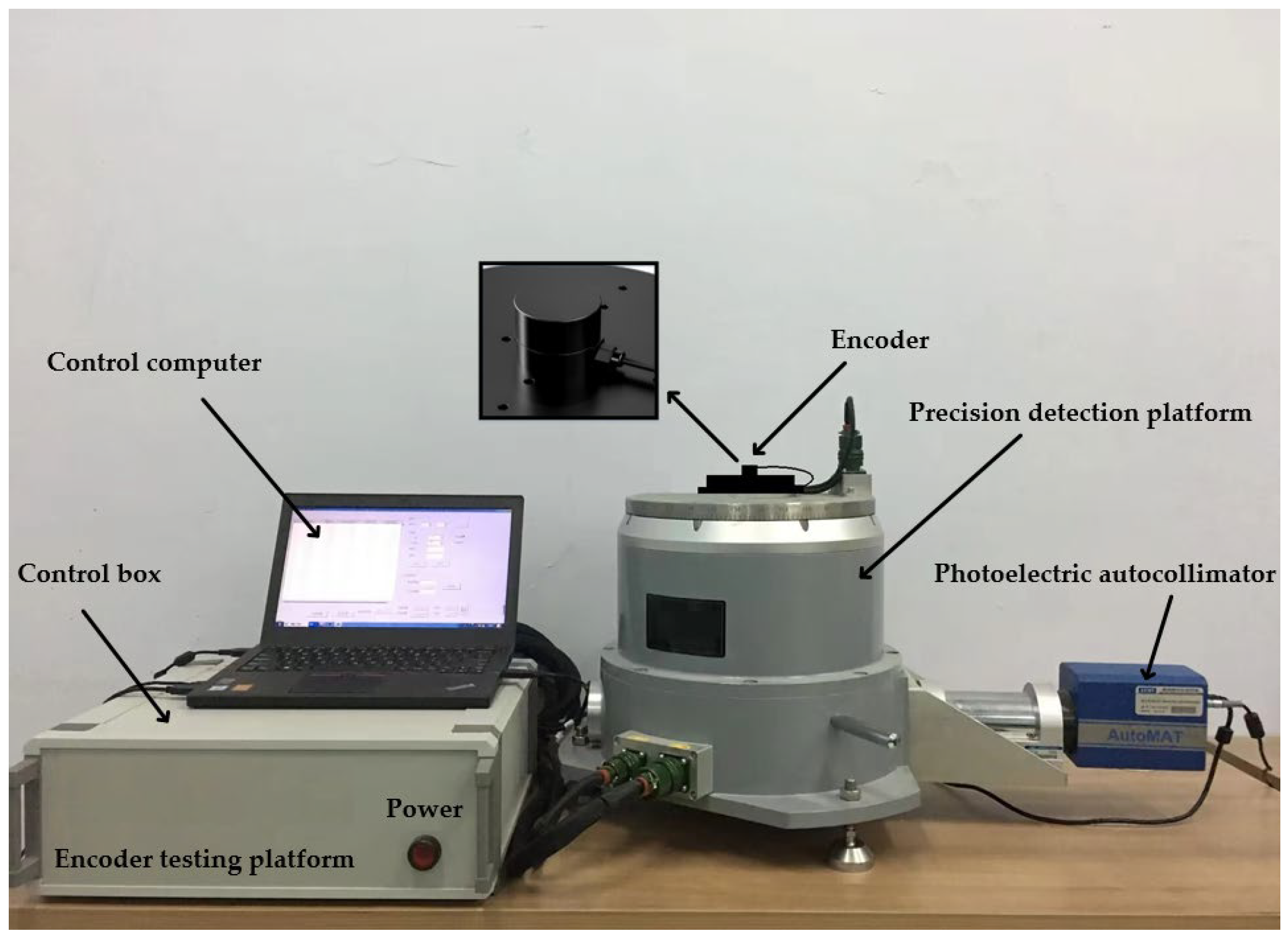
4. Experimental Results and Error Analysis

On the basis of the above principles and simulation analysis, a prototype of the encoder was designed and manufactured, with geometric dimensions as follows: Φ30 mm × 20 mm, with a resolution of 19 bits. Using the direct comparison method for accuracy detection, precision detection is carried out using the direct comparison method, as shown in Figure 11 and Figure 12. An optical position closed-loop is formed using an autocollimator and a regular polyhedron as an angle reference. A fixed-position optical reflector is also installed to detect signal drift of the autocollimator during the process. The detection device consists of a fast detection platform and a control box, which can transmit the collected data to the host for display during the displayed time period. Compare the readings of the photoelectric encoder and detection equipment directly to calculate the instrument’s angle measurement error. The measurement method is shown in the following figure, and the detection data are shown in Table 6.
The performance of the testing equipment is ±360°continuous or compensatory testing, and it adopts an internal and external dual axis structure. The positioning accuracy of the inner and outer axis angular positions is ±0.2”, the stability of the angular positions is ±0.36”, the verticality and rotation accuracy of the axis system are ≤±2”, and the angular positioning resolution is ≤0.36”.
The standard deviation of its angle measurement error can be used represented as σ, and its standard deviation can be expressed as:
x ¯ = i = 1 n x i n ,   δ i = x i x ¯ ,   σ = ( x 1 x ¯ ) 2 + ( x 2 x ¯ ) 2 + + ( x n x ¯ ) 2 n = i = 1 n δ i 2 n
In the formula, xi is the measured value, δ i is the random error, and x ¯ is the arithmetic mean of measured values.
According to Formula (4), it can be calculated that for the measurement error in both directions, the measurement accuracy of the photoelectric encoder is approximately 2.57”.
According to the sources of errors in the designer process of the encoders, encoder errors include theoretical errors, coding disc engraving errors and axis system errors, installation and debugging errors, etc. Among them, theoretical error is an inherent error in digital output devices, which is a fundamental error introduced during the conversion of analog signals to digital signals. The engraving error of the coding disk is caused by the engraving process, which introduces errors in the system when engraving the code track.

5. Conclusions

This article proposes a new type of encoder that achieves miniaturization, the matrix encoder and decoding circuit of the new encoder are designed and calculated, and simulation analysis is conducted on the designed encoder. The results show that the measurement accuracy can reach 2.57”(1σ). Compared with traditional research, the measurement accuracy has been significantly improved, which further demonstrates that the principles and methods proposed in this paper are practical and feasible. This is of great significance for improving the measurement accuracy of encoders and miniaturization.
The adoption of new encoding methods to reduce the size of the encoder disk and achieve the miniaturization of the encoder volume is an important development trend of photoelectric shaft angle encoders. The ultimate goal of absolute position coding research is to reduce the number of code tracks to one cycle, while also possessing the uniqueness and monotropy of traditional Gray codes. From this perspective, single-ring Gray codes are a perfect encoding. However, there are still many theoretical issues that urgently need to be addressed in the development of single-ring Gray code coding, which has become a new direction for its coding theory.

Author Contributions

Validation, L.G., G.C., C.S. and H.D.; formal analysis, L.G.; investigation, L.G.; data curation, L.G.; writing—original draft preparation, L.G.; writing—review and editing, G.C., L.G., C.S. and H.D.; funding acquisition, G.C. and H.D. All authors have read and agreed to the published version of the manuscript.

Funding

This research was funded by the Major National Scientific Instrument and Equipment Development Project of China (grant No. 2017YFF0105304) and the Key Research and Development Project of Science and Technology Development Plan of Jilin Provincial of China (No. 20200401117GX).

Institutional Review Board Statement

Not applicable.

Informed Consent Statement

Not applicable.

Data Availability Statement

Data are contained within the article.

Conflicts of Interest

The authors declare no conflicts of interest.

References

  1. Das, S.; Chakraborty, B. Design and Realization of an Optical Rotary Sensor. IEEE Sens. J. 2018, 18, 2675–2681. [Google Scholar] [CrossRef]
  2. Johnson, M. Polarimetric 360° absolute rotary encoder. Adv. Opt. Technol. 2022, 11, 13–16. [Google Scholar] [CrossRef]
  3. Xi, R.; Hu, J.; Guo, H.; Du, S. Research on a single-ring absolute coder disc encoding and decoding technology combined with Huffman coding. In Proceedings of AOPC 2019: Optoelectronic Devices and Integration and Terahertz Technology and Applications; SPIE: London, UK, 2019; Volume 11334, p. 1133404. [Google Scholar]
  4. Jankowska, K.; Dybkowski, M. Classification of Optoelectronic Rotary Encoder Faults Based on Deep Learning Methods in Permanent Magnet Synchronous Motor Drive System. Electronics 2023, 12, 4184. [Google Scholar] [CrossRef]
  5. Wang, Y.; Wang, R.; Yu, Y.; Yang, H. Small metal code disk based photoelectric encoder with high resolution. Laser Optoelectron Prog. 2019, 56, 180401. [Google Scholar] [CrossRef]
  6. Ying, S.; Qiuhua, W.; Ronghong, S. Subdivision error compensation method of small photoelectric encoder. J. Electron. Meas. Instrum. 2011, 25, 605–611. [Google Scholar]
  7. Iafolla, L.; Filipozzi, M.; Freund, S.; Zam, A.; Rauter, G.; Cattin, P.C. Proof of concept of a novel absolute rotary encoder. Sens. Actuators A Phys. 2020, 312, 112100. [Google Scholar] [CrossRef]
  8. Paul, S.; Chang, J. Design and Development of a Novel High-Resolution Absolute Rotary Encoder System Based on Affine n-digit N-ary Gray Code. J. Electr. Eng. Technol. 2018, 13, 943–952. [Google Scholar]
  9. Wan, Q.-H.; Wang, Y.-Y.; Sun, Y.; Yang, S.-W. A Novel Miniature Absolute Metal Rotary Encoder Based on Single-track Periodic Gray Code. In Proceedings of the IEEE International Conference on Instrumentation, Measurement, Computer, Communication & Control, Harbin, China, 8–10 December 2012. [Google Scholar]
  10. Iafolla, L.; Filipozzi, M.; Freund, S.; Zam, A.; Rauter, G.; Cattin, P.C. Machine learning-based method for linearization and error compensation of a novel absolute rotary encoder—ScienceDirect. Measurement 2020, 169, 108547. [Google Scholar] [CrossRef]
  11. Das, S.; Sarkar, T.S.; Chakraborty, B.; Dutta, H.S. Study on array of photo-detector based absolute rotary encoder. Sens. Actuators A Phys. 2016, 246, 114–122. [Google Scholar] [CrossRef]
  12. Baji’c, J.S.; Stupar, D.Z.; Daki’c, B.M.; Živanov, M.B.; Nagy, L.F. An absolute rotary position sensor based on cylindrical coordinate color space transformation. Sens. Actuators A Phys. 2015, 213, 27–34. [Google Scholar] [CrossRef]
  13. Pop, A.A. Incremental Encoder Speed Acquisition Using an STM32 Microcontroller and NI ELVIS. Sensors 2022, 22, 5127. [Google Scholar] [CrossRef] [PubMed]
  14. Matsuzoe, Y.; Tsuji, N.; Nakayama, T.; Fujita, K.; Yoshizawa, T. High-performance absolute rotary encoder using multitrack and M-code. Opt. Eng. 2003, 42, 124–131. [Google Scholar] [CrossRef]
  15. Hayashi, Y.; Shibata, S.; Kamabuchi, H.; Fukui, N.; Nashiki, M. Development of high resolution and compact absolute rotary encoder with batteryless multi-turn detecting function. J. Jpn. Soc. Precis. Eng. 2000, 66, 1177–1180. [Google Scholar] [CrossRef]
  16. Tresanchez, M.; Pallejà, T.; Teixidó, M.; Palacín, J. Using the image acquisition capabilities of the optical mouse sensor to build an absolute rotary encoder. Sens. Actuators A Phys. 2010, 157, 161–167. [Google Scholar] [CrossRef]
  17. Jiang, J.; Dai, J.; Yang, S.; Chang, Y. A 22-bit image encoder with optoelectronic integrated chip. Opt. Commun. 2022, 512, 128022. [Google Scholar] [CrossRef]
  18. Ren, W.; Jin, Z. Phase space visibility graph. Chaos Solitons Fractals 2023, 176, 114170. [Google Scholar] [CrossRef]
  19. Yang, X.; Liang, Y.; Zhang, W.; Wang, X.; Hao, D. Design of optoelectronic integrated chips for reflective encoders. Opt. Precis. Eng. 2023, 31, 1136–1149. [Google Scholar] [CrossRef]
  20. Yu, M.; Hou, N.; Wang, C.; Zhao, Y.; Chen, K.; Chi, Y. An Optoelectronic Detector with High Precision for Compact Grating Encoder Application. Electronics 2022, 11, 3486. [Google Scholar]
Figure 1. Explosion diagram of matrix encoder structure.
Sensors 24 01400 g001
Figure 2. Detection circuit of phototransistor.
Sensors 24 01400 g002
Figure 3. Code track distribution of matrix encoder.
Sensors 24 01400 g003
Figure 4. Planar expansion of matrix code tracks.
Sensors 24 01400 g004
Figure 5. Changes of a-ring detector in one reading cycle.
Sensors 24 01400 g005
Figure 6. MATLAB simulation principle flowchart.
Sensors 24 01400 g006
Figure 7. Decoding a-ring matrix code into a traditional Gray code circuit.
Sensors 24 01400 g007
Figure 8. Simulation results of the decoding module for a-ring code track.
Sensors 24 01400 g008
Figure 9. Schematic diagram of converting Gray code to binary code.
Sensors 24 01400 g009
Figure 10. Simulation results of converting Gray code to binary code.
Sensors 24 01400 g010
Figure 11. Three-dimensional model of optoelectronic encoder error detection platform.
Sensors 24 01400 g011
Figure 12. Optoelectronic encoder error detection platform.
Sensors 24 01400 g012
Table 1. Comparison of performance parameters of rotary encoders based on different measurement methods.
Encoding MethodNumber of Code TracksResolutionOptical CharacteristicsMonotropicAlgorithm ComplexityResponse Speed
Parallel LightFocusing and ImagingDetector
Gray Coden360/2nNoNoPhototransistorYesLowFast
Matrix code2360/2nNoNoPhototransistorYesMediumMedium
single-ring Gray code1Approaching 360/2nYesYesCCD or CMOSYesHighSlow
M-sequence code2360/2nYesYesCCD or CMOSNoHighSlow
image encoding0Subpixel, ang-ular second levelYesYesCCD or CMOSNoHighSlow
Table 2. Performance parameters of light-emitting diode (LED) SE2460.
ModelWavelengthDivergence AngleOutput PowerVoltageSpectral WidthSpectral Temperature Drift
ValueTest
Conditions
Maximum ValueTest Conditions
SE2460-003935 nm18°1.0 mWIF = 50 mA1.6VIF = 50 mA50 nm0.3 nm/°C
Table 3. Performance of phototransistor SD2440.
ModelLight CurrentReceiving AngleRise and Fall TimeDark Current
ValueTest ConditionsValueTest Conditions
SD2440-0031 mAVCE = 5 V
Radiancy H = 20 mW/cm2
24°15 μs100 nAVCE = 5 V
Table 4. Relationship between b-ring signal and traditional Gray code.
Code Area12345678910111213141516
Signal
b1A19A18A17A16A15A14A13A12A11A10A9A8A7A6A5A5
b2A18A17A16A15A14A13A12A11A10A9A8A7A6A5A5A19
b3A17A16A15A14A13A12A11A10A9A8A7A6A5A5A19A18
b4A16A15A14A13A12A11A10A9A8A7A6A5A5A19A18A17
b5A15A14A13A12A11A10A9A8A7A6A5A5A19A18A17A16
b6A14A13A12A11A10A9A8A7A6A5A5A19A18A17A16A15
b7A13A12A11A10A9A8A7A6A5A5A19A18A17A16A15A14
b8A12A11A10A9A8A7A6A5A5A19A18A17A16A15A14A13
b9A11A10A9A8A7A6A5A5A19A18A17A16A15A14A13A12
b10A10A9A8A7A6A5A5A19A18A17A16A15A14A13A12A11
b11A9A8A7A6A5A5A19A18A17A16A15A14A13A12A11A10
b12A8A7A6A5A5A19A18A17A16A15A14A13A12A11A10A9
b13A7A6A5A5A19A18A17A16A15A14A13A12A11A10A9A8
b14A6A5A5A19A18A17A16A15A14A13A12A11A10A9A8A7
b15A5A5A19A18A17A16A15A14A13A12A11A10A9A8A7A6
b16A5A19A18A17A16A15A14A13A12A11A10A9A8A7A6A5
Table 5. Correspondence between code area and logic code.
Code Area i123456
Gray codeB0000B0001B0011B0010B0110B0111
Logic code Mi A 1 ¯ A 2 ¯ A 3 ¯ A 4 ¯ A 1 ¯ A 2 ¯ A 3 ¯ A 4 A 1 ¯ A 2 ¯ A 3 A 4 A 1 ¯ A 2 ¯ A 3 A 4 ¯ A 1 ¯ A 2 A 3 A 4 ¯ A 1 ¯ A 2 A 3 A 4
Code area i789101112
Gray codeB0101B0100B1100B1101B1111B1110
Logic code Mi A 1 ¯ A 2 A 3 ¯ A 4 A 1 ¯ A 2 A 3 ¯ A 4 ¯ A 1 A 2 A 3 ¯ A 4 ¯ A 1 A 2 A 3 ¯ A 4 A 1 A 2 A 3 A 4 A 1 A 2 A 3 A 4 ¯
Code area i13141516
Gray codeB1010B1011B1001B1000
Logic code Mi A 1 A 2 ¯ A 3 A 4 ¯ A 1 A 2 ¯ A 3 A 4 A 1 A 2 ¯ A 3 ¯ A 4 A 1 A 2 ¯ A 3 ¯ A 4 ¯
Table 6. Detection data of matrix encoder.
Angle15°30°45°60°75°90°105°
Measuring error
(Prograde)
0”2.5”3.1”−2.4”2.3”−1.2”2.3”3.4”
Measuring error
(reversal)
0”3.2”2.6”−2.5”−1.83.1”−2.6”3.7”
Angle120°135°150°165°180°195°210°225°
Measuring error
(Prograde)
2.2”−1.9”1.6”2.5”−1.8”2.1”3.5”−2.4”
Measuring error
(reversal)
2”2.4”−3.5”1.9”−2.2”1.8”2.3”−1.6”
Angle240°255°270°285°300°315°330°345°
Measuring error
(Prograde)
2.6”3.1”−2.6”2.7”3.9”−2.6”3.1”2.2”
Measuring error
(reversal)
−2.1”3.2”−2.8”3.4”3.2”2.6”−1.2”3.3”
Disclaimer/Publisher’s Note: The statements, opinions and data contained in all publications are solely those of the individual author(s) and contributor(s) and not of MDPI and/or the editor(s). MDPI and/or the editor(s) disclaim responsibility for any injury to people or property resulting from any ideas, methods, instructions or products referred to in the content.

