

UWB Antenna with Enhanced Directivity for Applications in Microwave Medical Imaging


Abstract
1. Introduction
2. Antenna Design
2.1. Reference Antenna
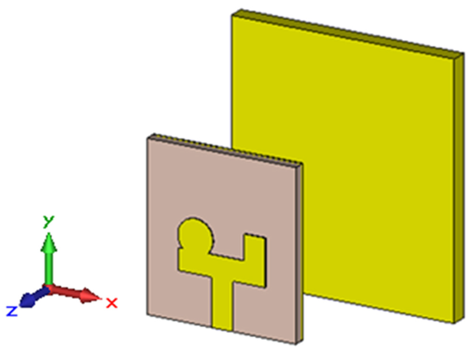
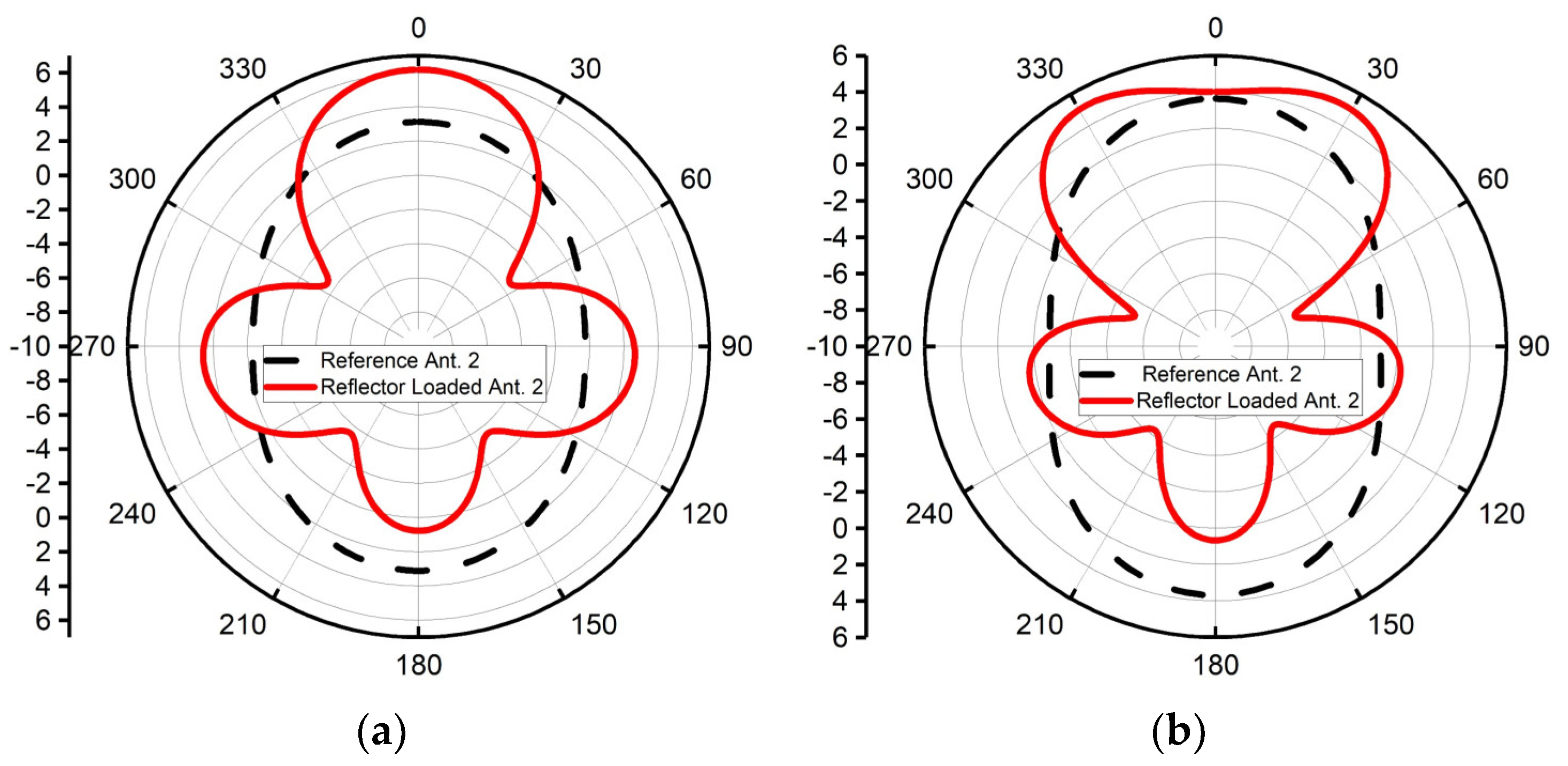
2.2. Proposed Design
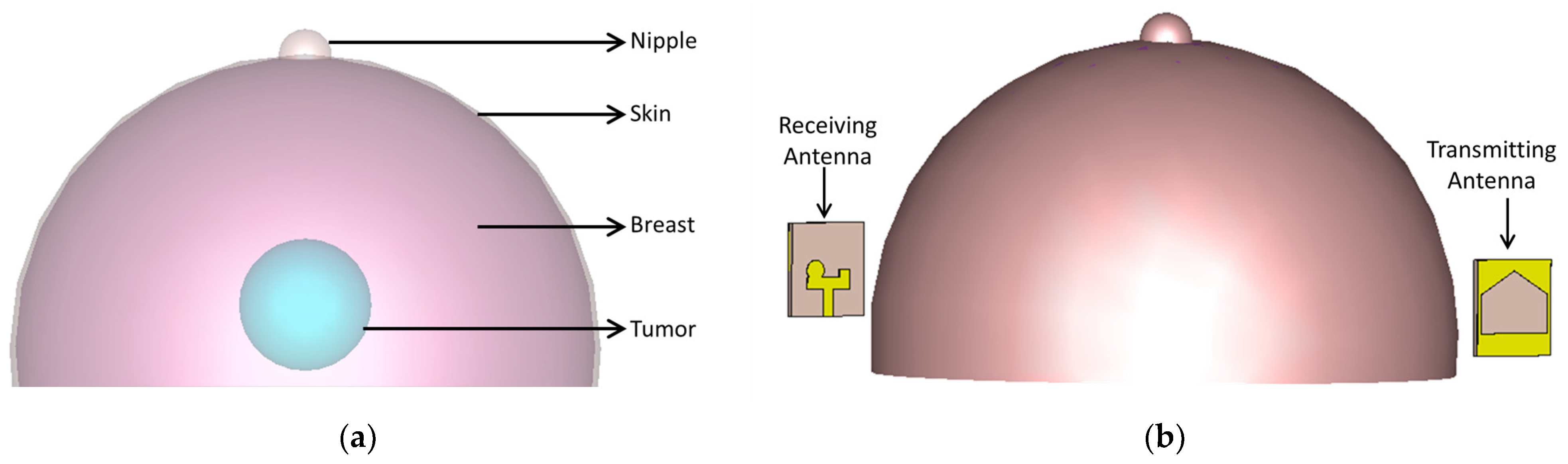
3. Application of the Proposed Antenna in Microwave Medical Imaging Systems
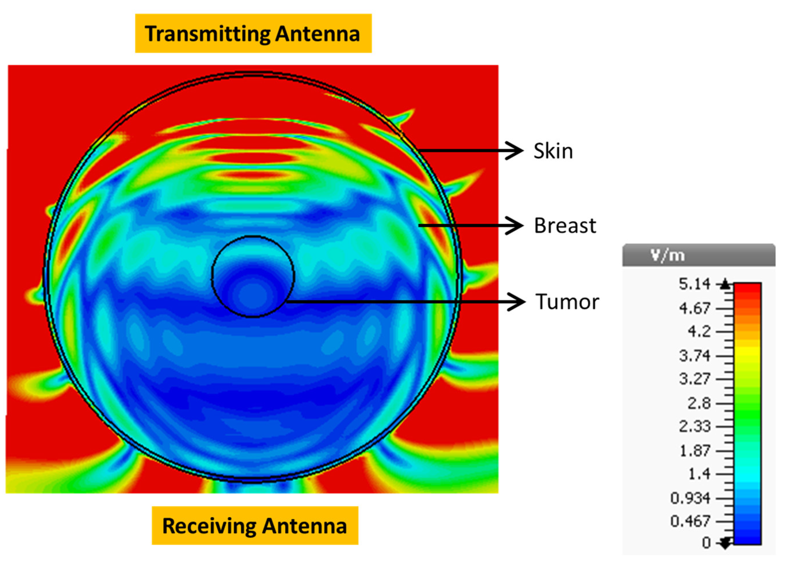
3.1. Field Analysis
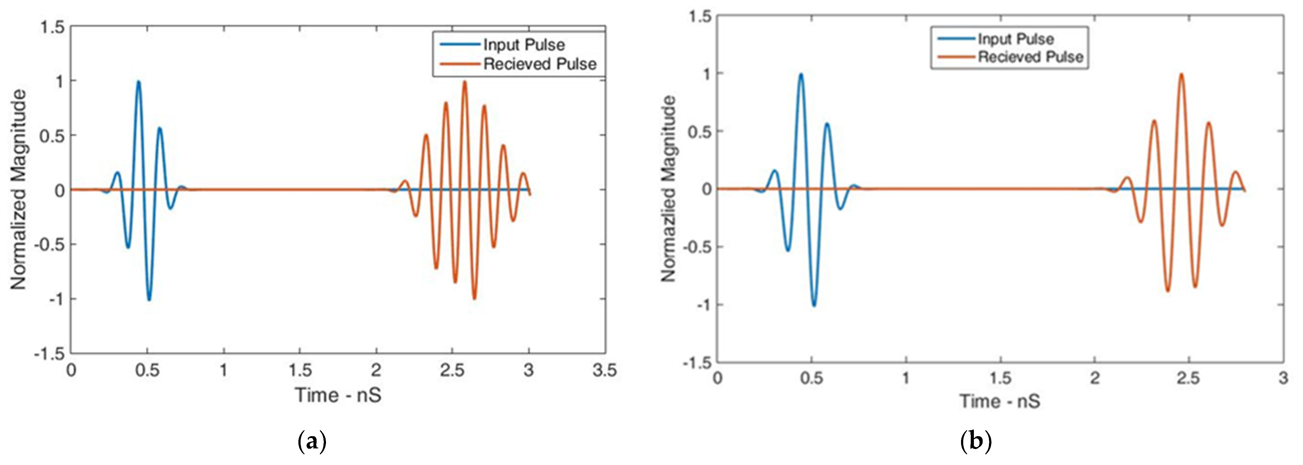
3.2. Time-Domain Analysis
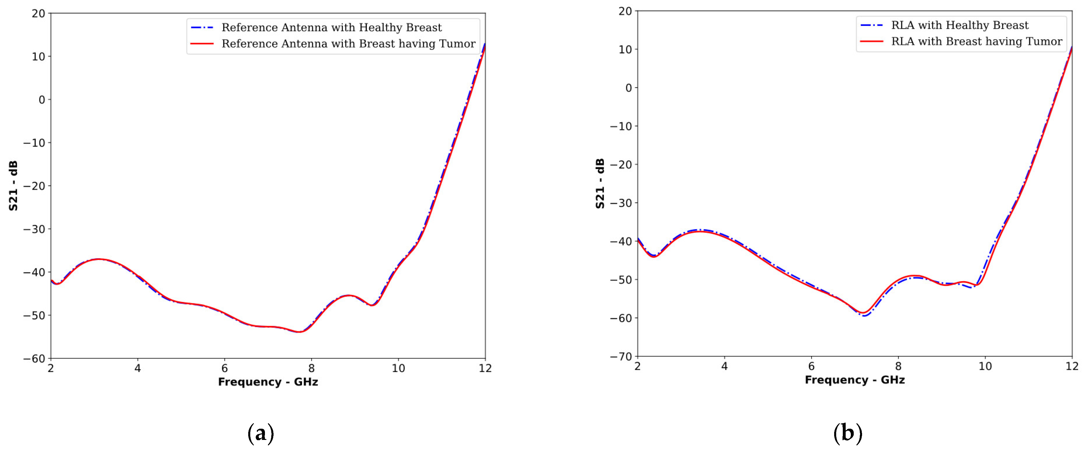
3.3. Frequency-Domain Analysis
4. Generality of the Technique
5. Comparison
6. Conclusions
Author Contributions
Funding
Institutional Review Board Statement
Informed Consent Statement
Data Availability Statement
Acknowledgments
Conflicts of Interest
References
- Islam, M.T.; Mahmud, M.Z.; Islam, M.T.; Kibria, S.; Samsuzzaman, M. A low cost and portable microwave imaging system for breast tumor detection using UWB directional antenna array. Sci. Rep. 2019, 9, 15491. [Google Scholar] [CrossRef]
- Conceição, R.C.; Mohr, J.J.; O’Halloran, M. (Eds.) An Introduction to Microwave Imaging for Breast Cancer Detection; Springer: Cham, Switzerland, 2016. [Google Scholar]
- Noghanian, S.; Sabouni, A.; Desell, T.; Ashtari, A. Microwave Tomography: Global Optimization, Parallelization and Performance Evaluation; Springer: New York, NY, USA, 2014. [Google Scholar]
- Fiser, O.; Helbig, M.; Sachs, J.; Ley, S.; Merunka, I.; Vrba, J. Microwave non-invasive temperature monitoring using UWB radar for cancer treatment by hyperthermia. Prog. Electromagn. Res. 2018, 162, 1–14. [Google Scholar] [CrossRef]
- Grzegorczyk, T.M.; Meaney, P.M.; Kaufman, P.A.; di Florio-Alexander, R.M.; Paulsen, K.D. Fast 3-D tomographic microwave imaging for breast cancer detection. IEEE Trans. Med. Imaging 2012, 31, 1584–1592. [Google Scholar] [CrossRef] [PubMed]
- Tobon Vasquez, J.A.; Scapaticci, R.; Turvani, G.; Bellizzi, G.; Rodriguez-Duarte, D.O.; Joachimowicz, N.; Duchêne, B.; Tedeschi, E.; Casu, M.R.; Crocco, L.; et al. A prototype microwave system for 3D brain stroke imaging. Sensors 2020, 20, 2607. [Google Scholar] [CrossRef] [PubMed]
- Merunka, I.; Massa, A.; Vrba, D.; Fiser, O.; Salucci, M.; Vrba, J. Microwave tomography system for methodical testing of human brain stroke detection approaches. Int. J. Antennas Propag. 2019, 2019, 4074862. [Google Scholar] [CrossRef]
- Rahama, Y.A.; Al Aryani, O.; Din, U.A.; Awar, M.A.; Zakaria, A.; Qaddoumi, N. Novel microwave tomography system using a phased array antenna. IEEE Trans. Microw. Theory Tech. 2018, 66, 5119–5128. [Google Scholar] [CrossRef]
- Dachena, C.; Fedeli, A.; Fanti, A.; Lodi, M.B.; Pastorino, M.; Randazzo, A. Microwave imaging for the diagnosis of cervical diseases: A feasibility analysis. IEEE J. Electromagn. RF Microw. Med. Biol. 2021, 5, 277–285. [Google Scholar] [CrossRef]
- Amin, B.; Shahzad, A.; Crocco, L.; Wang, M.; O’Halloran, M.; González-Suárez, A.; Elahi, M.A. A feasibility study on microwave imaging of bone for osteoporosis monitoring. Med. Biol. Eng. Comput. 2021, 59, 925–936. [Google Scholar] [CrossRef]
- Sachs, J.; Ley, S.; Just, T.; Chamaani, S.; Helbig, M. Differential ultra-wideband microwave imaging: Principle application challenges. Sensors 2018, 18, 2136. [Google Scholar] [CrossRef]
- Fear, E.C.; Li, X.; Hagness, S.C.; Stuchly, M.A. Confocal microwave imaging for breast cancer detection: Localization of tumors in three dimensions. IEEE Trans. Biomed. Eng. 2002, 49, 812–822. [Google Scholar] [CrossRef]
- Song, H.; Sasada, S.; Kadoya, T.; Okada, M.; Arihiro, K.; Xiao, X.; Kikkawa, T. Detectability of breast tumor by a hand-held impulse radar detector: Performance evaluation and pilot clinical study. Sci. Rep. 2017, 7, 16353. [Google Scholar] [CrossRef]
- Baran, A.; Kurrant, D.J.; Zakaria, A.; Fear, E.C.; LoVetri, J. Breast imaging using microwave tomography with radar-based tissue-regions estimation. Prog. Electromagn. Res. 2014, 149, 161–171. [Google Scholar] [CrossRef]
- Sabouni, A.; Flores-Tapia, D.; Noghanian, S.; Thomas, G.; Pistorius, S. Hybrid microwave tomography technique for breast cancer imaging. In Proceedings of the 2006 International Conference of the IEEE Engineering in Medicine and Biology Society, New York, NY, USA, 30 August–3 September 2006; pp. 4273–4276. [Google Scholar] [CrossRef]
- Bourqui, J.; Okoniewski, M.; Fear, E.C. Balanced antipodal Vivaldi antenna with dielectric director for near-field microwave imaging. IEEE Trans. Antennas Propag. 2010, 58, 2318–2326. [Google Scholar] [CrossRef]
- Li, X.; Hagness, S.C.; Choi, M.K.; Weide, D.W.V.D. Numerical and experimental investigation of an ultrawideband ridged pyramidal horn antenna with curved launching plane for pulse radiation. IEEE Antennas Wirel. Propag. Lett. 2003, 2, 259–262. [Google Scholar] [CrossRef]
- Di Clemente, F.S.; Helbig, M.; Sachs, J.; Schwarz, U.; Stephan, R.; Hein, M.A. Permittivity-matched compact ceramic ultra-wideband horn antennas for biomedical diagnostics. In Proceedings of the 5th European Conference on Antennas and Propagation (EUCAP), Rome, Italy, 11–15 April 2011; pp. 2386–2390. [Google Scholar]
- Jafari, H.M.; Deen, M.J.; Hranilovic, S.; Nikolova, N.K. A study of ultrawideband antennas for near-field imaging. IEEE Trans. Antennas Propag. 2007, 55, 1184–1188. [Google Scholar] [CrossRef]
- Alam, A.H.M.Z.; Islam, M.R.; Khan, S. Design and analysis of UWB rectangular patch antenna. In Proceedings of the 2007 Asia-Pacific Conference on Applied Electromagnetics, Melaka, Malaysia, 4–6 December 2007; pp. 1–3. [Google Scholar] [CrossRef]
- Yurduseven, O.; Smith, D.; Elsdon, M. Printed slot loaded bow-tie antenna with super wideband radiation characteristics for imaging applications. IEEE Trans. Antennas Propag. 2013, 61, 6206–6210. [Google Scholar] [CrossRef]
- Kanj, H.; Popovi’c, M. Miniaturized microstrip-fed ‘dark eyes’ antenna for near-field microwave sensing. IEEE Antennas Wirel. Propag. Lett. 2005, 4, 397–401. [Google Scholar] [CrossRef]
- Mousavi, S.M.H.; Rezaeieh, S.A.; Darvazehban, A.; Mohammed, B.; Janani, A.S.; Abbosh, A.M. Tapered Graded Index Lens Antenna with Enhanced Penetration for Near-Field Torso Imaging. IEEE Trans. Antennas Propag. 2022, 71, 78–88. [Google Scholar] [CrossRef]
- Fiser, O.; Hruby, V.; Vrba, J.; Drizdal, T.; Tesarik, J.; Vrba, J., Jr.; Vrba, D. UWB bowtie antenna for medical microwave imaging applications. IEEE Trans. Antennas Propag. 2022, 70, 5357–5372. [Google Scholar] [CrossRef]
- Sediq, H.T. Tumor detection concepts using eagle-shaped UWB antenna signals for medical purposes. Sens. Actuators A Phys. 2023, 362, 114653. [Google Scholar] [CrossRef]
- Samsuzzaman, M.; Islam, M.T.; Islam, M.T.; Shovon, A.A.; Faruque, R.I.; Misran, N. A 16-modified antipodal Vivaldi antenna array for microwave-based breast tumor imaging applications. Microw. Opt. Technol. Lett. 2019, 61, 2110–2118. [Google Scholar] [CrossRef]
- Li, Q.; Liu, Z.; Zhao, Y.; Zhao, R.; Fan, M.; Zhang, G.; Yu, M.; Han, P. A Portable Microwave Intracranial Hemorrhage Imaging System Based on PSO-MCKD-CEEMDAN Method. IEEE Trans. Microw. Theory Tech. 2023, 71, 773–783. [Google Scholar] [CrossRef]
- Amin, B.; Shahzad, A.; O’halloran, M.; Mcdermott, B.; Elahi, A. Experimental Validation of Microwave Imaging Prototype and DBIM-IMATCS Algorithm for Bone Health Monitoring. IEEE Access 2022, 10, 42589–42600. [Google Scholar] [CrossRef]
- Guo, L.; Alqadami, A.S.M.; Abbosh, A. Stroke Diagnosis Using Microwave Techniques: Review of Systems and Algorithms. IEEE J. Electromagn. RF Microw. Med. Biol. 2023, 7, 122–135. [Google Scholar] [CrossRef]
- Islam, M.T.; Samsuzzaman, M.; Rahman, M.N.; Islam, M.T. A compact slotted patch antenna for breast tumor detection. Microw. Opt. Technol. Lett. 2018, 60, 1600–1608. [Google Scholar] [CrossRef]
- Mobashsher, A.T.; Abbosh, A.M. Performance of directional and omnidirectional antennas in wideband head imaging. IEEE Antennas Wirel. Propag. Lett. 2016, 15, 1618–1621. [Google Scholar] [CrossRef]
- Martínez-Lozano, A.; Blanco-Angulo, C.; García-Martínez, H.; Gutiérrez-Mazón, R.; Torregrosa-Penalva, G.; Ávila-Navarro, E.; Sabater-Navarro, J.M. UWB-Printed Rectangular-Based Monopole Antenna for Biological Tissue Analysis. Electronics 2021, 10, 304. [Google Scholar] [CrossRef]
- Balanis, C.A. Antenna Theory: Analysis and Design; John Wiley & Sons: Hoboken, NJ, USA, 2016. [Google Scholar]
- Mehdipour, A.; Mohammadpour-Aghdam, K.; Faraji-Dana, R.; Kashani-Khatib, M.R. A novel coplanar waveguide-fed slot antenna for ultrawideband applications. IEEE Trans. Antennas Propag. 2008, 56, 3857–3862. [Google Scholar] [CrossRef]
- Islam, M.M.; Islam, M.T.; Faruque, M.R.I.; Samsuzzaman, M.; Misran, N.; Arshad, H. Microwave imaging sensor using compact metamaterial UWB antenna with a high correlation factor. Materials 2015, 8, 4631–4651. [Google Scholar] [CrossRef]
- Alqahtani, A.; Islam, M.T.; Talukder, M.S.; Samsuzzaman, M.; Bakouri, M.; Mansouri, S.; Almoneef, T.; Dokos, S.; Alharbi, Y. Slotted monopole patch antenna for microwave-based head imaging applications. Sensors 2022, 22, 7235. [Google Scholar] [CrossRef]
- Zerrad, F.E.; Taouzari, M.; Makroum, E.M.; Aoufi, J.E.; Qanadli, S.D.; Karaaslan, M.; Al-Gburi, A.J.A.; Zakaria, Z. Microwave Imaging Approach for Breast Cancer Detection Using a Tapered Slot Antenna Loaded with Parasitic Components. Materials 2023, 16, 1496. [Google Scholar] [CrossRef] [PubMed]
- Mahmud, M.Z.; Islam, M.T.; Samsuzzaman, M.; Kibria, S.; Misran, N. Design and parametric investigation of directional antenna for microwave imaging application. IET Microw. Antennas Propag. 2017, 11, 770–778. [Google Scholar] [CrossRef]
- Islam, M.S.; Islam, M.T.; Hoque, A.; Islam, M.T.; Amin, N.; Chowdhury, M.E. A portable electromagnetic head imaging system using metamaterial loaded compact directional 3D antenna. IEEE Access 2021, 9, 50893–50906. [Google Scholar] [CrossRef]
- Rokunuzzaman, M.; Samsuzzaman, M.; Islam, M.T. Unidirectional wideband 3-D antenna for human head-imaging application. IEEE Antennas Wirel. Propag. Lett. 2016, 16, 169–172. [Google Scholar] [CrossRef]


| Parameter | Maximum Value Associated with the Reference Antenna | Maximum Value Associated with the Proposed RLA (Simulated) | Maximum Value Associated with the Proposed RLA (Measured) |
|---|---|---|---|
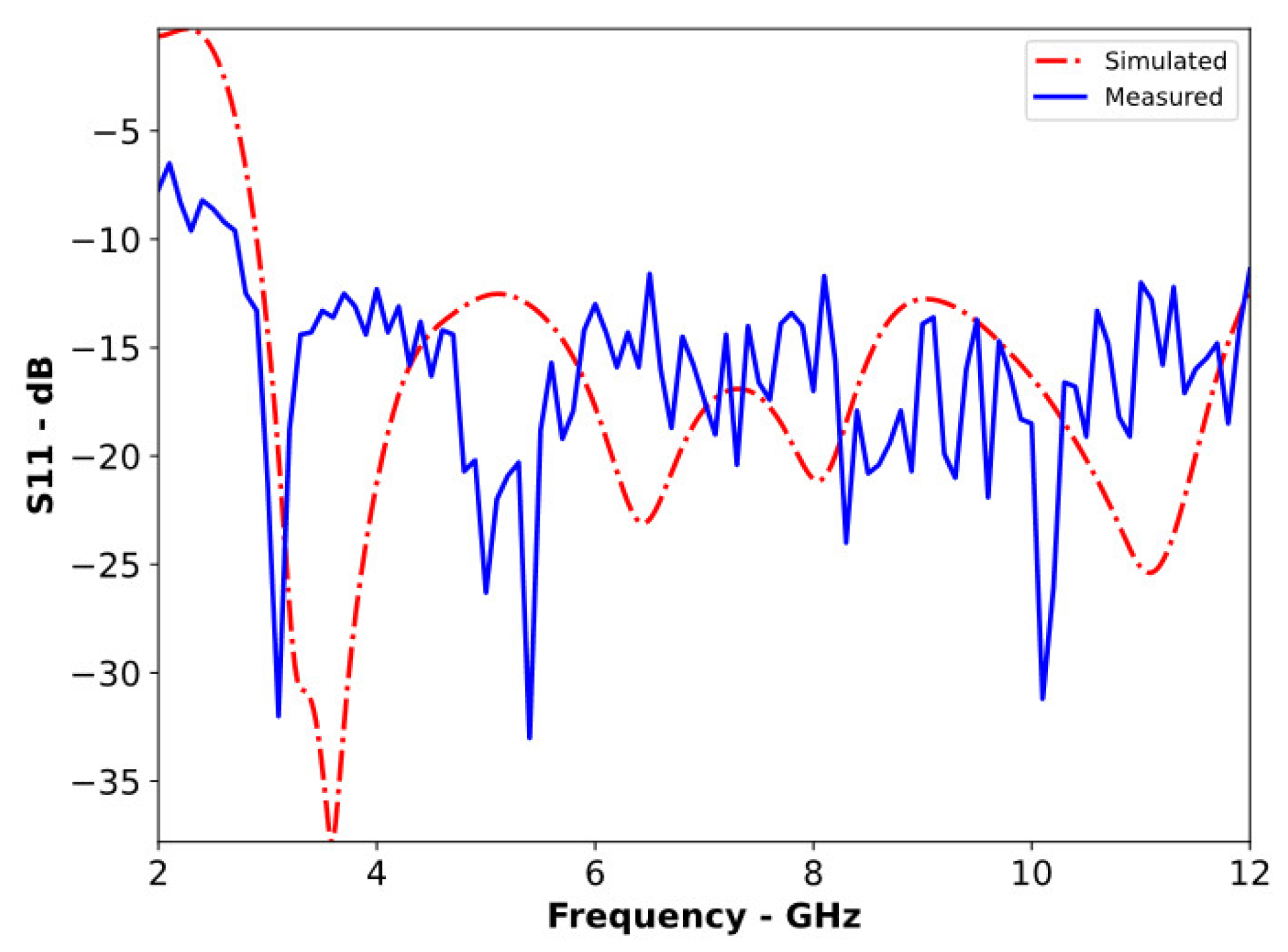
| Operating Bandwidth | 3.00 to 12 GHz | 3.02 to 12 GHz | 2.8 to 12 GHz |
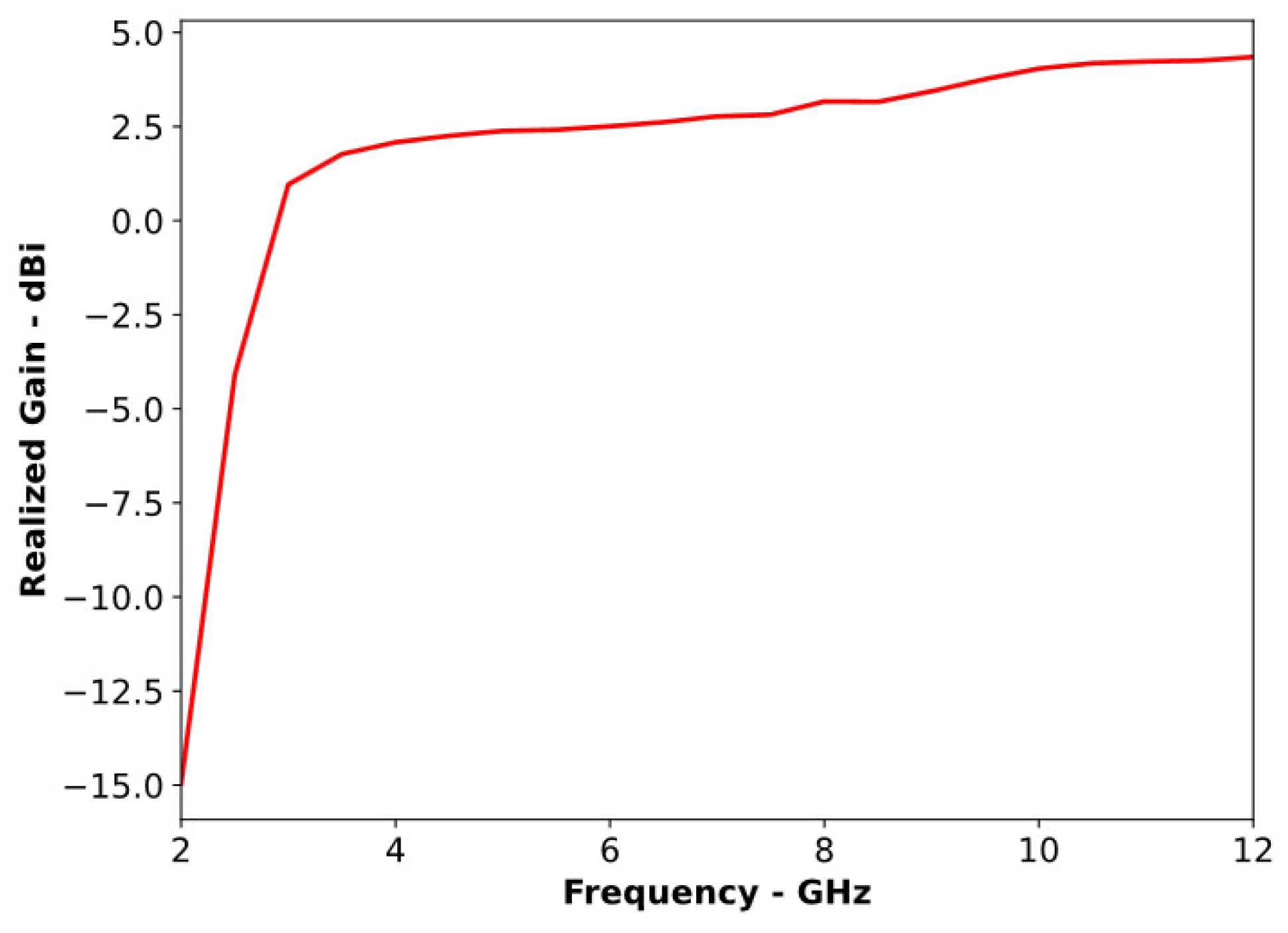
| Realized Gain | 4.3 dBi | 7.3 dBi | 7.8 dBi |
| Front-to-Back Ratio | 7.5 | 14.6 | 12.9 |
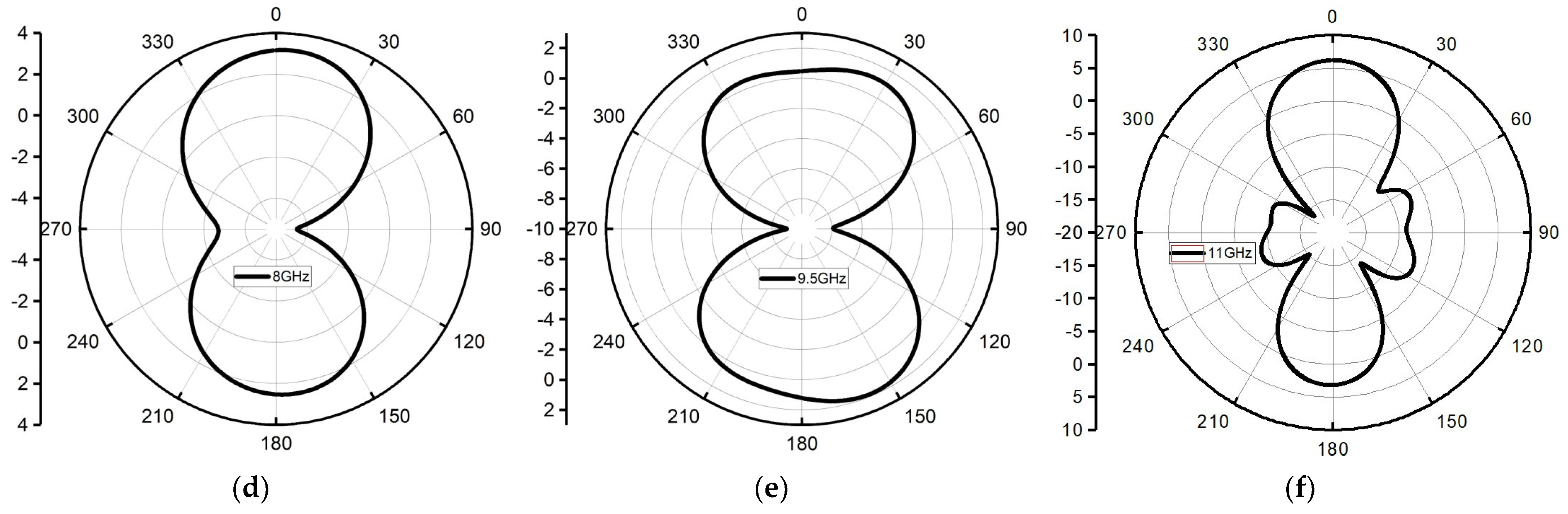
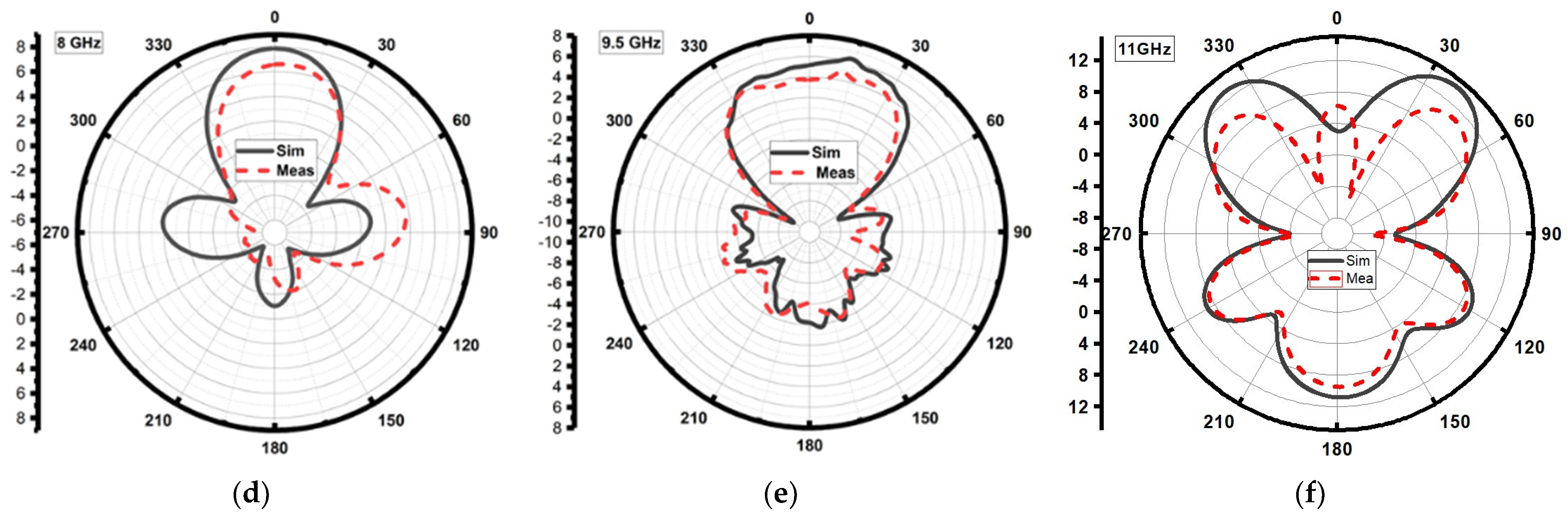
| Radiation Pattern | Non-directional throughout the operating band | Directional throughout the operating band | Directional throughout the operating band |
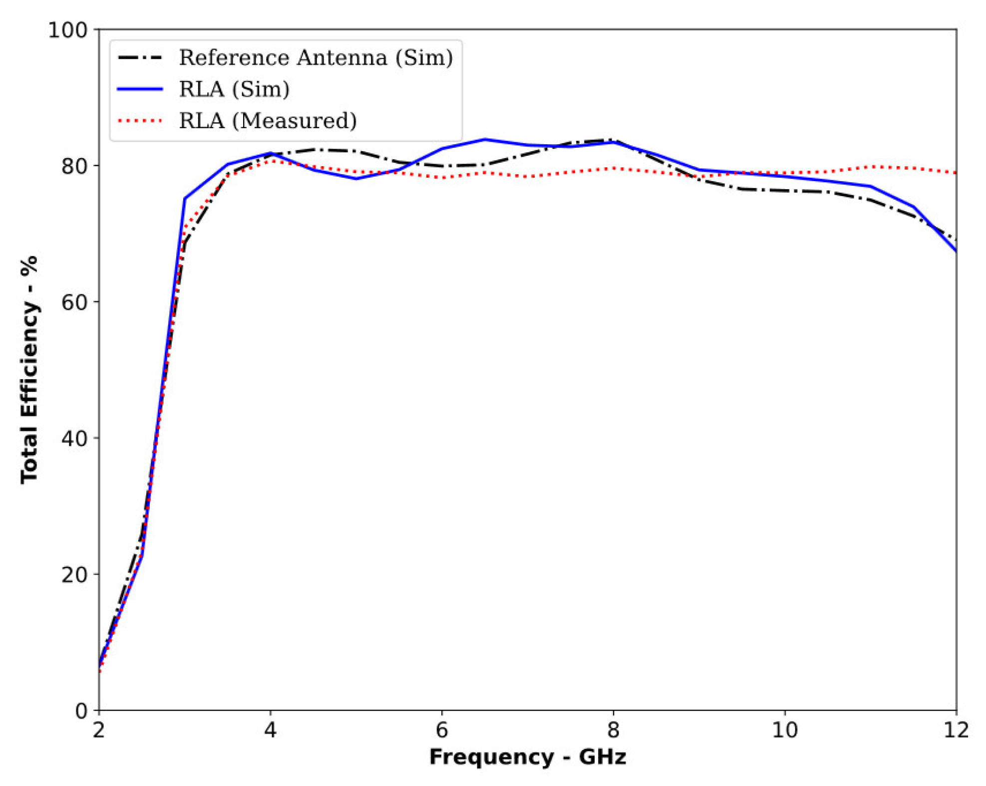
| Total Efficiency | 83% | 85% | 80% |
| Frequency (GHz) | Maximum E-Field with the Reference Antenna (V/m) | Maximum E-Field with the Proposed RLA (V/m) | Increase in Field Intensity (dB) |
|---|---|---|---|
| 3.5 | 0.36 | 1.87 | 14.26 |
| 4.6 | 0.36 | 1.56 | 12.73 |
| 5.0 | 0.25 | 0.96 | 11.68 |
| 6.5 | 0.26 | 1.16 | 12.98 |
| 8.0 | 0.32 | 1.26 | 11.90 |
| Frequency (GHz) | Maximum E-Field with the Reference Antenna (V/m) | Maximum E-Field with the Proposed RLA (V/m) | Increase in Field Intensity (dB) |
|---|---|---|---|
| 3.5 | 1.29 | 1.49 | 1.25 |
| 4.6 | 1.32 | 1.53 | 1.28 |
| 5.0 | 1.29 | 1.61 | 1.24 |
| 6.5 | 1.24 | 2.31 | 5.40 |
| 8.0 | 0.90 | 1.51 | 4.49 |
| Probe Position | Correlation Factor (%) | |
|---|---|---|
| ∅ = 90° | θ = −90° | 95.67 |
| ∅ = 90° | θ = −45° | 97.78 |
| ∅ = 90° | θ = 0° | 98.79 |
| ∅ = 90° | θ = 45° | 98.58 |
| ∅ = 90° | θ = 90° | 80.00 |
| Probe Position | Correlation Factor (%) | |
|---|---|---|
| ∅ = 0° | θ = −90° | 98.87 |
| ∅ = 0° | θ = −45° | 94.40 |
| ∅ = 0° | θ = 0° | 84.00 |
| ∅ = 0° | θ = 45° | 94.21 |
| ∅ = 0° | θ = 90° | 98.82 |
| Analyzed Parameter | Maximum Value Associated with the Reference Antenna | Maximum Value Associated with the Proposed RLA |
|---|---|---|
| Field strength inside the tumor | 0.36 V/m | 1.87 V/m |
| Time-domain pulse correlation factor | 94.59% | 94.86% |
| Difference between S21 in the absence and presence of a tumor | 0.98 dB | 2.15 dB |
| Reference | Antenna Size in mm (Electrical Size) | Operating Bandwidth | Peak Gain (dBi) | Correlation Factor | Max. Increase in the Penetrated Field Strength | Correlation Factor Calculated in Both the E-Plane and H-Plane | Generality of the Proposed Technique |
|---|---|---|---|---|---|---|---|
| [23] | 110 × 110 × 48 ) | 0.43 to 1.85 | N/A | N/A | 11 dB | N/A | No |
| [24] | 60 × 60 × 50 ) | 1 to 6 | N/A | 80 | N/A | N/A | No |
| [26] | 40 × 40 | 2.5 to 11 | 7.1 | 98 | N/A | N/A | No |
| [31] | ) | 1.25 to 2.4 | ~4 | ~90 | 5 dB | Yes | No |
| [37] | ) | 3.8 to 10.1 | 6.8 | 91.6 | N/A | N/A | No |
| [38] | 45 × 37 ) | 3.9 to 9.15 | 6.8 | 92 | N/A | N/A | No |
| [39] | ) | 1.12 to 2.5 | 5.192 | 80 | N/A | N/A | No |
| [40] | ) | 2.65 to 2.91 | 6.6 | N/A | N/A | N/A | No |
| Proposed RLA | ) | 3.02 to 12 | 7.3 | 94.86 | 14.26 dB | Yes | Yes, Proved |
Disclaimer/Publisher’s Note: The statements, opinions and data contained in all publications are solely those of the individual author(s) and contributor(s) and not of MDPI and/or the editor(s). MDPI and/or the editor(s) disclaim responsibility for any injury to people or property resulting from any ideas, methods, instructions or products referred to in the content. |
© 2024 by the authors. Licensee MDPI, Basel, Switzerland. This article is an open access article distributed under the terms and conditions of the Creative Commons Attribution (CC BY) license (https://creativecommons.org/licenses/by/4.0/).
Share and Cite
Awan, D.; Bashir, S.; Khan, S.; Al-Bawri, S.S.; Dalarsson, M. UWB Antenna with Enhanced Directivity for Applications in Microwave Medical Imaging. Sensors 2024, 24, 1315. https://doi.org/10.3390/s24041315
Awan D, Bashir S, Khan S, Al-Bawri SS, Dalarsson M. UWB Antenna with Enhanced Directivity for Applications in Microwave Medical Imaging. Sensors. 2024; 24(4):1315. https://doi.org/10.3390/s24041315
Chicago/Turabian StyleAwan, Dawar, Shahid Bashir, Shahid Khan, Samir Salem Al-Bawri, and Mariana Dalarsson. 2024. "UWB Antenna with Enhanced Directivity for Applications in Microwave Medical Imaging" Sensors 24, no. 4: 1315. https://doi.org/10.3390/s24041315
APA StyleAwan, D., Bashir, S., Khan, S., Al-Bawri, S. S., & Dalarsson, M. (2024). UWB Antenna with Enhanced Directivity for Applications in Microwave Medical Imaging. Sensors, 24(4), 1315. https://doi.org/10.3390/s24041315