

A Lightweight Method for Detecting and Correcting Errors in Low-Frequency Measurements for In-Orbit Demonstrators


Abstract
1. Introduction
1.1. An Introduction to the Application Scenario
1.2. Traditional EDAC Approaches
1.3. Traditional EDAC Approaches for Cost-Saving and Power-Constrained MCU-Based Systems
2. Algorithms: Definition and Test Procedure
2.1. Analysis of Bit-Flippling Cases and Methods of Implementation
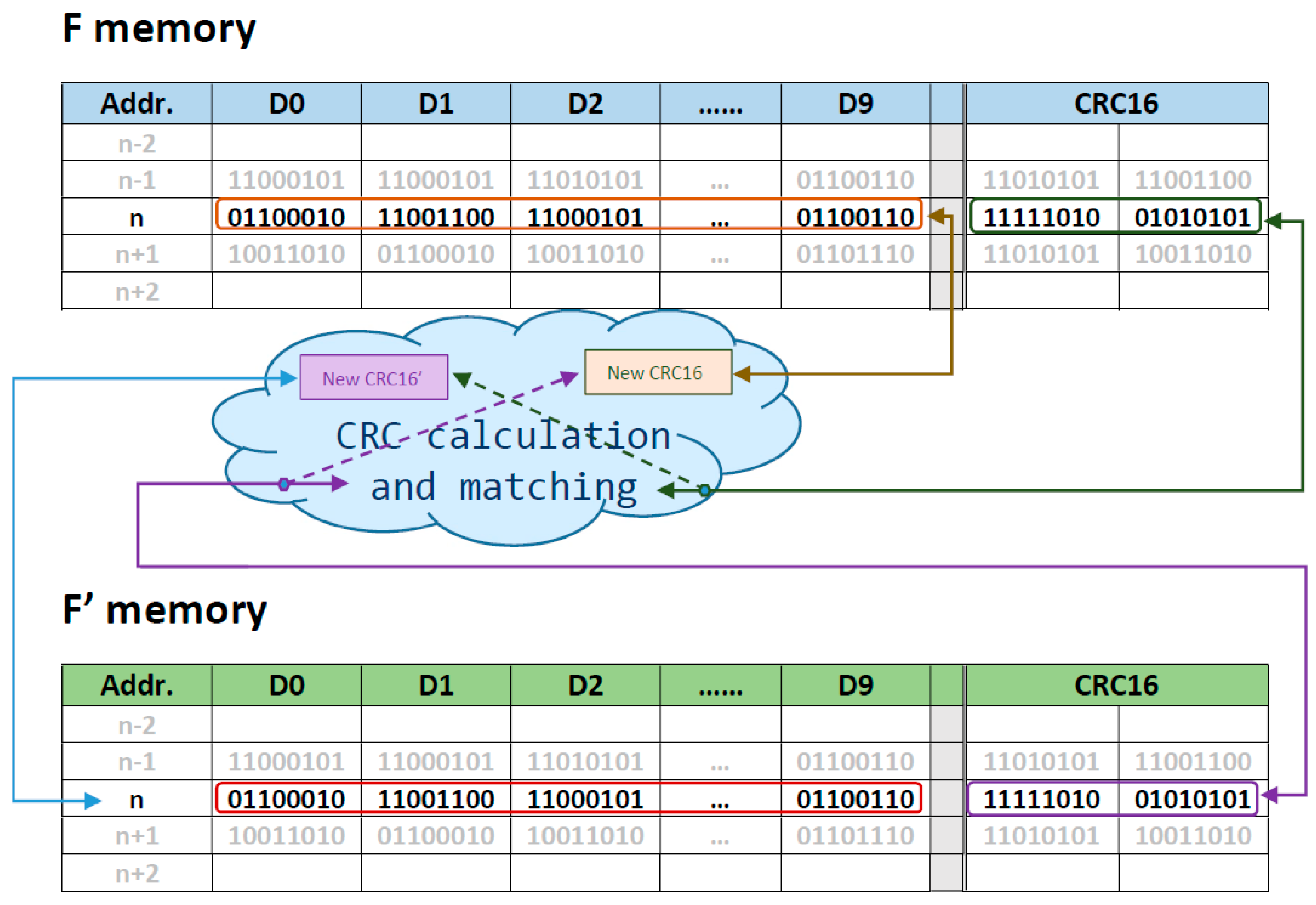
2.1.1. The Cross-Checking and Mirroring Technique (CCM)
| Technique CCM: Write process |
| 1. The CRC is calculated for data(i) → CRC_WR(i) 2. A new register is composed joining data(i) and CRC16 → DATA_WR(i) 3. DATA_WR(i) is written twice, in F and in F’→ DATA_WR(i) and DATA_WR’(i) |
| Technique CCM (#1): Read process |
| 1. A datum is read from F and F’ memories → DATA_RD(i) = data(i) + CRC_WR(i) DATA_RD’(i)= data’(i) + CRC_WR’(i) 2. if (data(i) == data’(i)) then data(i) is correct else 2.1. The CRC of data(i) in DATA_RD(i) is calculated → CRC_RD(i) 2.2. if (CRC_RD(i)== CRC_WR(i)) data(i) is correct and consequently data’(i) is corrupt else 2.2.1. The CRC of data’(i) in DATA_RD’(i) is calculated→ CRC_RD’(i) 2.2.2. if (CRC_RD’(i)== CRC_WR’(i)) data’(i)is correct and consequently data’(i) is corrupt else data(i)and data’(i)are discarded |
| Technique CCM (#2): Read process |
| 1. A datum is read from F memory → DATA_RD(i) = data(i) + CRC_WR(i) 2. The CRC of data(i) in DATA_RD(i)is calculated→ CRC_RD(i) 3. if (CRC_RD(i)== CRC_WR(i)) data(i) is correct else 3.1. Read data’(i) in F’ → DATA_RD’(i)= data’(i) + CRC_WR’(i) 3.2. if (CRC_RD(i)== CRC_WR’(i)) data(i) is sent because CRC_WR(i) is corrupt else 3.2.1. Calculate CRC for data’(i) → CRC_RD’(i) 3.2.2. if (CRC_RD’(i)== CRC_WR’(i)) data’(i) is sent and consequently data(i) is corrupt else data(i) and data’(i) are discarded |
| Technique CCM (#3): Read process |
| 1. Required datum is read from F and F’ DATA_RD(i) = data(i) + CRC_WR(i) DATA_RD’(i)= data’(i) + CRC_WR’(i) 2. if (data(i) == data’(i)) data(i) is correct and sent else 2.1. The CRC is calculated for data(i) in DATA_RD(i) → CRC_RD(i) 2.2. if (CRC_RD(i)== CRC_WR(i)) data(i) is correct and consequently data’(i) is corrupt else 2.2.1. The CRC is calculated for data’(i) → CRC_RD’(i) 2.2.2. if (CRC_RD’(i)== CRC_WR’(i)) data’(i) is correct and consequently data(i) is corrupt else 2.2.2.1 If (CRC_RD’(i)== CRC_WR(i)) data’(i) is correct and data(i) is corrupt else data(i) and data’(i) are discarded |
| Technique CCM (#4): Read process |
| 1. A datum is read from F → DATA_RD(i) = data(i) + CRC_WR(i) 2. The CRC of data(i) is calculated→ CRC_RD(i) 3. if (CRC_RD(i)== CRC_WR(i)) data(i) is correct else 3.1. Read data’(i) in F’ → DATA_RD’(i) data’(i) + CRC_WR’(i) 3.2. if (CRC_RD(i)== CRC_WR’(i)) data(i) is sent and consequently CRC_WR(i) is corrupt else 3.2.1. Calculate CRC for data’(i) → CRC_RD’(i) 3.2.2. if (CRC_RD’(i)== CRC_WR’(i)) data’(i) is sent and consequently, DATA(i) OR CRC_WR(i) are corrupt else 3.2.2.1. if (CRC_RD’(i)== CRC_WR(i)) data’(i) is sent and consequently, DATA(i) OR CRC_WR’(i) are corrupt else data(i) and data’(i) are discarded |
2.1.2. Evaluation Indicators
- Energy consumption index (I): This index refers to the average energy required by the payload for both writing and reading actions, measured from the average current during the execution of the evaluated routine. In this test phase, only the microcontroller, memory, and minimum auxiliary digital circuits are in the on-state. Energy efficiency is a tight constraint in onboard electronics due to the limited power generation and storage capacity of nanosatellites.
- Writing time in the flash memory (tWR): The MELISA payload must perform the measurements within a precise time period. After each new measurement, the scientific data must be written before a new one starts. This constraint limits the duration of the writing process in the external flash memory.
- Reading time in the flash memory (tRD): in contrast to tWR, the reading time is less constrained since the scientific data is required from the OBC in a 12-byte package one-to-one, and therefore the time can be tuned. However, since the OBC is required to read data from all the payloads and subsystems of the nanosatellite, it is essential to minimize this processing time.
- Discarded data number (Ddn): every version of the CCM technique aims to reduce the number of discarded data due to flipped bits. A lower Ddn value indicates a more effective technique.
- MCU Program Memory occupancy (PMo): The different techniques explore different strategies to mitigate the consequences of the corrupted data. To achieve this goal, they introduce additional instructions in the payload main program; as a result, the percentage of the MCU program memory is increased.
- MCU Data Memory occupancy (DMo): According to the actions described in the previous indicator, the MCU data memory are also increased by the additional instructions.
- Data Flash Memory occupancy (FMo): Modern designs tend to use SSD flash memory as scientific data storage. The MELISA payload incorporates a flash memory to fulfill the required storage capacity of the experiment. Redundancy involves storing multiple copies of data on the device to ensure valid data will be valid. Two copies of information and some EDAC help to ensure redundancy and correctness in space applications. The flash memory is faster than the older magnetic media but is over 12 times more expensive. This indicator estimates the increase in the price of the payload based on the chosen technique.
2.2. Methods
Indicators Assessment
- Writing time in flash (tWR) is a particularly critical parameter due to the tight timing required in the Melisa experiment. Roughly a million measurements take place during a MELISA experiment, and each must be written to the memory within a time of 10 ms. The averaging function of an oscilloscope is used for the multiple data acquired during the Melisa experiment, yielding the mean value of the writing time. It must be taken into account that the writing time should be the same for all versions, as the writing process is the same in each of them.
- The same method is applied to measure the Reading time in the flash memory (tRD). However, unlike the writing time, in the MELISA experiment, the reading process is commanded one by one. On the other hand, in each version of the CCM technique, the reading time varies depending on the type of error found in the data. This situation forces the manual measurement of the time for each readout. To achieve this, the benchmark stated before is written in the flash memory. Then, every time a new reading is commanded, the oscilloscope shows the reading time for one datum, and it is recorded in a spreadsheet. As the benchmark includes a total of eighty data points, the reading time for each technique version is obtained by calculating their average.
- Energy consumption index (I): a precision ammeter (Keysight 344,70 A, 7 ½ Digits) is used to measure the current demanded by the Melisa board while it is reading all the data in the benchmark in a row. The instrument is configured to measure current in the range of mA, as the maximum current drained by Melisa when in an idle state is 5.47 mA. It was also configured to optimize measurements by adjusting the smoothing level, response speed, and sampling interval.
3. Results
4. Discussion
- The tWR (Write time) indicator confirms that the writing time constraint is fulfilled for Melisa. It is within the 10 ms required, despite the additional tasks included in the CCM approach. This is to calculate a CCR16, aggregate it into the scientific register, and write the whole register twice in the flash memory.
- The tRD (Read time average) indicator represents the average time for reading all the data in the first benchmark. Although there are no errors, the read time has increased due to the process of error detection by calculating the CRC16. CCM #1 and #3 present the slowest read time, whereas #2 and #4 are roughly the same as the original time.
- The memory indicators allow us to know how many bytes occupy the program after including the CCM technique. They represent the bytes occupied in the MCU program and data memory. As can be seen in Table 2, the extra amount of bytes in the program memory is approximately 10%, and in the data memory, it is 0%. Both results are acceptable for the chosen 8-bit MCU, which features 128 kB of program memory and 4 kB of data.
- Energy consumption, Deleted data numbers, and Robustness indicators are not discussed because they do make sense in a fault-free scenario. They will be reviewed based on the results obtained with the benchmark, including faults.
- As can be expected, the tWR indicator for the synthetic benchmark remains equal to that in Table 2.
- The tRD indicator, for all types of data, is expected to be longer than in the previous test. Once a datum has been read from the primary memory and an error is detected, the CCM method must continue reading the redundant memory, trying to find the correct data. As can be seen in Table 3, once again, CCM #1 and #3 present the slowest average read time, whereas CCM #2 and #4 are faster.
- The best-case value provides additional information about the read time in the event that the datum is correct. The worst-case scenario shows the read time employed by the CCM technique when it detects an error and tries to find out what the correct scientific data are, making use of the redundancy memory. The best-case value is especially important because it is supposed that most of the data are going to be correct, and therefore it could be closer to real-time than the average evaluated value.
- The memory indicators change regarding the first benchmark.
- Energy consumption: The MELISA payload operates under tight consumption constraints because there are many other experiments hosted on the nanosatellite, all of which must share the power supply. However, as can be noticed from Table 3, the increase in consumption resulting from the introduction of the CCM scheme can be neglected, even in the worst-case scenario when the program spends more time reading the correct data. The maximum increase in consumption is less than 110 µA.
- Discarded data number: CCM #3 presents only 6 discarded data out of 16, namely 37.5%. Table 1 depicts the 16 types of error that can occur depending on the position of the bit suffering from bit-flip, whether it is in the CRC or the data fields, both in a primary memory datum and a redundancy memory datum. This means that CCM #3 is capable of recovering more incorrect data than any other.
- A robustness indicator is included to show if the algorithm could send incorrect data in the unlikely case of the bit flipped being in the same position of the datum, either in the primary or the redundancy memory. CCM #2 and #4 ensure this does not occur, unlike #1 and #3, which are not able to detect this type of error.
5. Conclusions
Author Contributions
Funding
Institutional Review Board Statement
Informed Consent Statement
Data Availability Statement
Acknowledgments
Conflicts of Interest
References
- Amaro-Seoane, P. Laser Interferometer Space Antenna. arXiv 2017, arXiv:1702.00786. [Google Scholar]
- Mateos, I.; Díaz-Aguiló, M.; Ramos-Castro, J.; García-Berro, E.; Lobo, A. Interpolation of the magnetic field at the test masses in eLISA. Class. Quantum Gravity 2015, 32, 165003. [Google Scholar] [CrossRef]
- Mateos, I.; Ramos-Castro, J.; Lobo, A. Low-frequency noise characterization of a magnetic field monitoring system using an anisotropic magnetoresistance. Sens. Actuators A Phys. 2015, 235, 57–63. [Google Scholar] [CrossRef]
- Mateos, I.; Sánchez-Mínguez, R.; Ramos-Castro, J. Design of a CubeSat payload to test a magnetic measurement system for space-borne gravitational wave detectors. Sens. Actuators A Phys. 2018, 273, 311–316. [Google Scholar] [CrossRef]
- Mateos, I.; María-Moreno, C.; Pacheco-Ramos, G.; Quirós-Olozábal, A.; Guerrero-Rodríguez, J.; Cifredo-Chacón, M.; del Sol, I.; Cobos-Sánchez, C.; Vílchez-Membrilla, J.; Rivas, F. Increasing the technological maturity of a low-noise magnetic measurement subsystem with IOD/IOV CubeSat Platforms. In Highlights of Spanish Astrophysics XI, Proceedings of the XV Scientific Meeting of the Spanish Astronomical Society, La Laguna, Spain, 4–9 September 2022; Sociedad Española de Astronomia: La Laguna, Spain, 2023. [Google Scholar]
- Maestro, J.; Reviriego, P. Study of the Effects of MBUs on the Reliability of a 150 nm SRAM Device. In Proceedings of the 45th Annual Conference on Design Automation—DAC’08, Anaheim, CA, USA, 8–13 June 2008; Association for Computing Machinery: New York, NY, USA, 2008. [Google Scholar]
- Radaelli, D.; Puchner, H.; Wong, S.; Daniel, S. Investigation of multi-bit upsets in a 150 nm technology SRAM device. IEEE Trans. Nucl. Sci. 2005, 52, 2433–2437. [Google Scholar] [CrossRef]
- Chen, D.; Wilcox, E.; Ladbury, R.L.; Kim, H.; Phan, A.; Seidleck, C.; LaBel, K.A. Heavy Ion Irradiation Fluence Dependence for Single-Event Upsets in a NAND Flash Memory. IEEE Trans. Nucl. Sci. 2016, 64, 332–337. [Google Scholar] [CrossRef]
- Buddhanoy, M.; Kumari, P.; Surendranathan, U.; Was, M. Total Ionizing Dose Effects on Long-Term Data Retention Characteristics of Commercial 3-D NAND Memories. IEEE Trans. Nucl. Sci. 2022, 69, 390–396. [Google Scholar] [CrossRef]
- Neubauer, A.; Freudenberger, J.; Kühn, V. Coding Theory: Algorithms, Architectures and Applications; John Wiley & Sons: Hoboken, NJ, USA, 2007. [Google Scholar]
- Kahe, G. Reliable flight computer for sounding rocket with dual redundancy: Design and implementation based on COTS parts. Int. J. Syst. Assur. Eng. Manag. 2017, 8, 560–571. [Google Scholar] [CrossRef]
- Kahe, G. Triple-Triple Redundant Reliable Onboard Computer Based on Multicore Microcontrollers. Int. J. Reliab. Risk Saf. Theory Appl. 2018, 1, 17–24. [Google Scholar] [CrossRef]
- Xilinx, A. Triple Modular Redundancy (TMR) v1.0 LogiCORE IP Product Guide (PG268). 28 April 2022. Available online: https://docs.xilinx.com/r/en-US/pg268-tmr/Feature-Summary (accessed on 18 December 2022).
- LaMeres, B.; Harkness, S.; Handley, M.; Moholt, P.; Julien, C.; Kaise, T.; Klumpar, D.; Mashburn, K.; Springer, L.; Crum, G. RadSat—Radiation Tolerant SmallSat Computer System. In Proceedings of the AIAA/USU Conference on Small Satellites, Logan, UT, USA, 10 August 2015. [Google Scholar]
- Chen, C.; Hsiao, M. Error-correcting codes for semiconductor memory applications: A state-of-the-art review. IBJ J. Res. Dev. 1984, 58, 124–134. [Google Scholar] [CrossRef]
- Fujiwara, E. Code Design for Dependable Systems: Theory and Practical Application; Wiley-Interscience: New York, NY, USA, 2006. [Google Scholar]
- Castro, H.D. A correction code for multiple cells upsets in memory devices for space applications. In Proceedings of the 14th IEEE International New Circuits and Systems Conference, Vancouver, BC, Canada, 26–29 June 2016; IEEE: Piscataway, NJ, USA, 2016. [Google Scholar]
- Sánchez-Macián, A.; Tabero, J.; Regadío, A.; Maestre, J.; Reviriego, P. SEFI pro-tection for Nanosat 16-bit Chip On-Board Computer Memories. IEEE Trans. Device Mater. Reliab. 2017, 17, 698–707. [Google Scholar] [CrossRef]
- Hamming, R. Error detecting and error correcting codes. Bell Syst. Tech. J. 1950, 29, 147–160. [Google Scholar] [CrossRef]
- Argyrides, C.; Zarandi, H.; Pradhan, D. Matrix Codes: Multiple Bit Upsets Tolerant Method for SRAM Memories. In Proceedings of the 22nd IEEE International Symposium on Defect and Fault-Tolerance in VLSI Systems, Rome, Italy, 26–28 September 2007; IEEE: Piscataway, NJ, USA, 2007. [Google Scholar]
- Silva, F.; Muniz, A.; Silveira, J.; Marcon, C. An Adaptive Implementation of the Column Line Code (CLC) ECC. In Proceedings of the 33rd Symposium on Integrated Circuits and Systems Design (SBCCI), Campinas, Brazil, 24–28 August 2020; IEEE: Piscataway, NJ, USA, 2020. [Google Scholar]
- Goerl, R.; Villa, P.R.; Poehls, L.; Bezerra, E.; Vargas, F. An efficient EDAC approach for handling multiple bit upsets in memory array. Microelectron. Reliab. 2018, 88–90, 214–218. [Google Scholar] [CrossRef]
- Saiz-Adalid, L. Flexible Unequal Error Control Codes with Selectable Error Detection and Correction Levels. In Proceedings of the 32th International Conference on Computer Safety, Reliability and Security (SAFECOMP), Toulouse, France, 24–27 September 2013; Springer: Berlin/Heidelberg, Germany, 2013. [Google Scholar]
- Gracia-Morán, J.; Saiz-Adalid, L.; Tomás, D.G. Improving Error Correction Codes for Multiple-Cell Upsets in Space Applications. IEEE Trans. Very Large Scale Integr. (VLSI) Syst. 2018, 26, 2132–2142. [Google Scholar] [CrossRef]
- The Error Correcting Codes (ECC) Page. Available online: https://eccpage.com (accessed on 2 January 2024).


 ’ highlights one or more flipped bits in that data field, while the ‘
 ’ symbol indicates a data field without faults.
’ highlights one or more flipped bits in that data field, while the ‘’ symbol indicates a data field without faults.
’ symbol indicates a data field without faults.
’ highlights one or more flipped bits in that data field, while the ‘’ symbol indicates a data field without faults.| Primary Memory (F) | Redundant Memory (F’) | |||
|---|---|---|---|---|
| DATA_WR(i) | DATA_WR(i) | |||
| Data(i) | CRC_WR | Data’(i) | CRC_WR’ | |
 |  |  |  | |
 |  |  |  | |
 |  |  |  | |
 |  |  |  | |
 |  |  |  | |
 |  |  |  | |
 |  |  |  | |
 |  |  |  | |
 |  |  |  | |
 |  |  |  | |
 |  |  |  | |
 |  |  |  | |
 |  |  |  | |
 |  |  |  | |
 |  |  |  | |
 |  |  |  | |
| Indicator | Original | CCM v.1 | CCM v.2 | CCM v.3 | CCM v.4 |
|---|---|---|---|---|---|
| tRD—Read time average (us) | 260.6 | 300.2 | 264.5 | 300.2 | 264.3 |
| Read time (Best case) (us) | 300.1 | 254.9 | 300.1 | 254.9 | |
| Read time (Worst case) (us) | 300.2 | 271.7 | 300.3 | 271.7 | |
| tWR—Write time (us) | 151 | 662.7 | |||
| Ddn—Discarded data | It is not necessary, 0 discarding happens. | ||||
| Robustness | It is not necessary, no error is possible. | ||||
| PMo—Program memory (bytes) (*) | 5048 | 5510 | 5638 | 5720 | 5740 |
| DMo—Data memory (bytes) (*) | 431 | 431 | |||
| FMo—Flash occupancy (Mbytes) | 12.36 | 29.66 | |||
| I—Energy consumption Index (mA) | Not measured | ||||
| Indicator | Original | CCM v.1 | CCM v.2 | CCM v.3 | CCM v.4 |
|---|---|---|---|---|---|
| tRD—Read time average (us) | 260.6 | 458.26 | 442.28 | 457.66 | 442.85 |
| Read time (Best case) (us) | 300.2 | 267.3 | 300.2 | 267.3 | |
| Read time (Worst case) (us) | 555.7 | 528.7 | 566.8 | 547 | |
| tWR—Write time (us) | 151 | 662.7 | |||
| Ddn—Discarded data | 0 | 8 | 8 | 6 | 7 |
| 0% | 50% | 50% | 37.5% | 43.75% | |
| Robustness (*) | No | No | Yes | No | Yes |
| PMo—Program memory (bytes) (**) | 5134 | 5510 | 5638 | 5720 | 5740 |
| Memory increasing (%) | - | +7.3% | +9.82% | +11.4% | +11.8% |
| DMo—Data memory (bytes) (**) | 431 | ||||
| FMo—Flash occupancy (Mbytes) | 12.36 | 29.66 | |||
| I—Energy consumption Index (mA) | 7041 | 7065 +0.34% | 70,955 +0.79% | 7075 +0.48% | 7104 +0.895% |
| Indicator | CCM v.1 | CCM v.2 | CCM v.3 | CCM v.4 |
|---|---|---|---|---|
| Ddn—Discarded data | 8 | 8 | 6 | 7 |
| Ddn—% Discarded data | 50% | 50% | 37.5% | 43.75% |
| Ddn—Corrected data | 8 | 8 | 10 | 9 |
| Ddn—% Corrected data | 50% | 50% | 62.50% | 56.25% |
Disclaimer/Publisher’s Note: The statements, opinions and data contained in all publications are solely those of the individual author(s) and contributor(s) and not of MDPI and/or the editor(s). MDPI and/or the editor(s) disclaim responsibility for any injury to people or property resulting from any ideas, methods, instructions or products referred to in the content. |
© 2024 by the authors. Licensee MDPI, Basel, Switzerland. This article is an open access article distributed under the terms and conditions of the Creative Commons Attribution (CC BY) license (https://creativecommons.org/licenses/by/4.0/).
Share and Cite
Cifredo-Chacón, M.-Á.; Guerrero-Rodríguez, J.-M.; Mateos, I. A Lightweight Method for Detecting and Correcting Errors in Low-Frequency Measurements for In-Orbit Demonstrators. Sensors 2024, 24, 1065. https://doi.org/10.3390/s24041065
Cifredo-Chacón M-Á, Guerrero-Rodríguez J-M, Mateos I. A Lightweight Method for Detecting and Correcting Errors in Low-Frequency Measurements for In-Orbit Demonstrators. Sensors. 2024; 24(4):1065. https://doi.org/10.3390/s24041065
Chicago/Turabian StyleCifredo-Chacón, María-Ángeles, José-María Guerrero-Rodríguez, and Ignacio Mateos. 2024. "A Lightweight Method for Detecting and Correcting Errors in Low-Frequency Measurements for In-Orbit Demonstrators" Sensors 24, no. 4: 1065. https://doi.org/10.3390/s24041065
APA StyleCifredo-Chacón, M.-Á., Guerrero-Rodríguez, J.-M., & Mateos, I. (2024). A Lightweight Method for Detecting and Correcting Errors in Low-Frequency Measurements for In-Orbit Demonstrators. Sensors, 24(4), 1065. https://doi.org/10.3390/s24041065