Article

High-Performance CP Magneto-Electric Dipole Antenna Fed by Printed Ridge Gap Waveguide at Millimeter-Wave

by
Zahra Mousavirazi
1,
Mohamed Mamdouh M. Ali
2,
Peyman PourMohammadi
1,*,
Peng Fei
3 and
Tayeb A. Denidni
1
1
Centre-Energie Materiaux et Telecommunications, Institut National de la Recherche Scientifique, Montreal, QC H5A 1K6, Canada
2
Electrical Engineering Department, Assiut University, Assiut 71515, Egypt
3
Beijing Institute of Radio Metrology and Measurement, Beijing 100854, China
*
Author to whom correspondence should be addressed.
Sensors 2024, 24(24), 8183; https://doi.org/10.3390/s24248183
Submission received: 4 November 2024 / Revised: 28 November 2024 / Accepted: 19 December 2024 / Published: 21 December 2024
(This article belongs to the Section Communications)

Abstract

:
This paper presents a high-performance circularly polarized (CP) magneto-electric (ME) dipole antenna optimized for wideband millimeter-wave (mm-wave) frequencies, specifically targeting advancements in 5G and 6G technologies. The CP antenna is excited through a transverse slot in a printed ridge gap waveguide (PRGW), which operates in a quasi-transverse electromagnetic (Q-TEM) mode. Fabricated on Rogers RT 3003 substrate, selected for its low-loss and cost-effective properties at high frequencies, the design significantly enhances both impedance and axial ratio (AR) bandwidths. The antenna achieves an impressive impedance bandwidth of 31% (25.24–34.50 GHz) and an AR bandwidth of 24.9% (26.40–33.91 GHz), with a peak gain of up to 8.4 dBic, demonstrating a high cross-polarization level. The experimental results validate the high-performance characteristics of the antenna, making it a robust candidate for next-generation wireless communication systems requiring CP capabilities.

1. Introduction

Millimeter-wave (mm-wave) technology is rapidly emerging as a pivotal element in advancing the next-generation of wireless communication systems, such as 5G and the forthcoming 6G networks [1,2,3,4,5]. Operating at these higher frequencies offers the dual benefits of expansive bandwidths and the potential for ultra-fast data rates, making mm-wave a highly attractive option for future wireless applications. Engineers and researchers are pushing the boundaries of what is possible in wireless network performance, capacity, and efficiency to fully leverage the capabilities of mm-wave technology [6].
The transition to mm-wave frequencies is primarily driven by the need for higher data rates and lower latency, alongside the availability of previously under-utilized mm-wave spectrum. However, the deployment of mm-wave technologies introduces several substantial challenges. These include overcoming significant path losses, signal attenuation from atmospheric conditions, and physical blockages such as buildings and foliage [7,8,9,10].
The design and development of mm-wave antenna systems must address factors such as impedance bandwidth, efficiency, size, material selection, and manufacturing precision to ensure effective communication links [11,12,13,14,15,16]. High-gain antennas are particularly crucial in mm-wave applications due to their ability to focus transmitted signals into a narrow beam thus concentrating energy in the intended direction. This focused beamforming helps to compensate for the high propagation losses and attenuation typical of mm-wave signals. By enhancing the range and reliability of communication links, high-gain antennas also optimize power usage, reduce interference, and mitigate environmental disturbances, which altogether boost the overall system performance.
Moreover, circularly polarized (CP) antennas are proving to be indispensable in the realm of mm-wave communications. Their ability to mitigate multipath interference and improve signal reception in dynamic environments enhances their utility in complex wireless landscapes. CP antennas are favored for their capability to minimize the adverse effects of polarization mismatch and reflections, which are common challenges in high-frequency communication scenarios. With the ongoing development of CP antennas featuring wideband capabilities and high-gain, these antennas are set to play a crucial role in the effective deployment of mm-wave technology, particularly in mobile and fixed wireless applications [17,18,19,20,21,22,23].
Techniques for designing CP antennas are classified into single-fed and dual/multi-fed types. The single-fed CP antennas are less complicated due to the simple feeding structure but are limited by the relatively narrow axial ratio (AR) bandwidth. Even though multi-fed CP antennas improve the operating bandwidth effectively, they increase the structure complexity owing to the presence of dual or multi ports. Hence, they are not suitable for next-generation space-limited applications. The CP antennas with a single-feed are mostly preferred to reduce the loss and achieve a compact size. Various technologies to improve the operating bandwidth of single-fed CP antennas such as patch antenna, L- and U-shaped slot antenna [24,25], cavity-backed slot antenna [26], helix and spiral antenna [17,27,28], magneto-electric (ME) dipole antenna [29,30], and S-, L- and cross-shaped dipole antenna [31,32,33] were explored for mm-wave applications [34]. Among these, the ME dipole antenna has emerged as the preferred choice for CP antenna design due to its exceptional efficiency in circular polarization and its ability to maintain stable signal transmission over a wide range of frequencies [35,36].
The ME-dipole element, serving as a complementary source antenna, is renowned for its expansive operational bandwidth and excellent radiation properties, making it ideal for applications that demand robust and efficient wireless communications [37]. By integrating the properties of both magnetic and electric dipoles, the ME-dipole antenna offers outstanding circular polarization and delivers stable, strong signal transmission across a wide frequency range, which is essential for modern high-frequency communication systems. Research on designing ME dipole antennas for next-generation mm-wave applications highlights several innovative feeding techniques to enhance performance, especially in circular polarization [2,14].
Key approaches include L-shaped probe feeds, which stabilize performance across wide frequency ranges, and microstrip line feeds that simplify the design while effectively supporting circular polarization. Additionally, some designs incorporate metallic walls around the ME-dipole elements, paired with a microstrip power divider for feeding, significantly expanding the axial ratio bandwidth and improving polarization. These methods, including combinations of substrate-integrated waveguide (SIW) and microstrip techniques, underscore the adaptability of ME-dipole antennas in meeting the rigorous demands of modern high-frequency communication systems [36,38,39]. In [29,30], low-profile ME-dipole antennas exited by a SIW feed network were reported to achieve a wide impedance bandwidth. However, both antennas had narrow axial ratio (AR) bandwidths of approximately 16% and 13%, respectively. To improve the AR bandwidth, a CP ME-dipole antenna was proposed in [40], which involved designing a double-sided printed electric dipole based on SIW. This led to an increased AR bandwidth of about 36.6% but at the expense of increased antenna size. Moreover, with the increase in frequency, the transmission loss of the SIW feeding networks is inevitable.
A novel waveguide structure known as the ridge gap waveguide (RGW) was developed to address these challenges, targeting high-frequency applications in 5G communication systems [41]. This innovative approach overcomes the limitations of traditional waveguides by facilitating lower-loss transmission and broader bandwidth capabilities, making it an ideal choice for modern high-frequency communication systems.
Over the past decade, significant research has focused on RGW technology to develop high-efficiency. These low-loss transmission lines minimize complexity by eliminating the need for metal connections, particularly at high frequencies. Introduced in 2009 as a novel low-loss transverse electromagnetic (TEM) guiding structure, RGW was further developed into its printed version, the printed ridge gap waveguide (PRGW), by 2011 [42,43]. This iteration offers an economical solution for mm-wave frequencies and employs a quasi-transverse electromagnetic mode of propagation, enhancing its suitability for applications requiring high precision and efficiency in compact forms.
PRGW technology is distinguished by its low-loss and minimal dispersion compared to traditional printed circuit board (PCB)-based structures, making it highly effective for high-frequency applications. It enables the integration of planar transmission lines with other circuit components, which is crucial for designing low-cost and low-profile physical structures. In RGW setups, electric and magnetic waves are tightly confined between two metal walls with open sidewalls, allowing propagation through the air gap. This unique configuration significantly reduces losses compared to SIW technologies, where waves traverse through both air and the host dielectric material, incurring higher losses [44,45,46].
In [47], a high-gain CP ME-dipole antenna element fed by PRGW was implemented to excite a high-mode cavity. However, only narrow impedance and AR bandwidths of about 13% were obtained in [12]; a high-efficiency CP ME-dipole based on PRGW technology using a three-layer dual-polarized split-ring resonator lens has achieved a sufficient gain above 10dBic. However, the proposed structure has a narrow impedance and AR bandwidth. Additionally, using a three-layer lens above the antenna adds more losses and difficulties in fabrication, especially for large antenna arrays. Although a CP antenna element designed in [18] has a low-profile structure, it suffers from a narrow AR bandwidth of 10%, which is insufficient for 5G applications.
This paper proposes a wideband and compact CP antenna element fed by PRGW technology designed with a single-feed configuration at 28 GHz. Circular polarization in this antenna is achieved through the upper part of the antenna as a magneto-electric dipole antenna. In similar works, circular polarization is created through dual-feed configuration, which adds design complexity, or via an additional layer placed above the magneto-electric dipole antenna, introducing extra complexity and height to the antenna. We have employed a fork-shaped feed structure to increase the bandwidth, which has led to promising results alongside the PRGW technology. The simulated and experimental results agree well and indicate a wide impedance bandwidth of about 31% from 25.24 to 34.50 GHz. It is worth noting that the main objective of this paper is to improve the bandwidth of the CP antenna by integrating a novel ME-dipole antenna into a single-layered substrate. This allows for creating a wideband CP antenna element without needing a complex feed network or additional layers. It is also worth mentioning that all antenna layers are designed using Rogers RT 3003, a high-performance substrate optimized for high-frequency applications. With a dielectric constant (εr) of 3, this material is ideal for scenarios that demand minimal signal delay and phase shift, such as 5G network antennas. Rogers RT 3003 is renowned for its low dielectric loss, which enhances efficiency by minimizing power loss at higher frequencies. Additionally, its combination of affordability and high-performance makes it a compelling choice for designing cost-effective, yet highly efficient, high-frequency components.

2. ME-Dipole Antenna Design Procedure

The 3-D view of the proposed mm-wave CP ME-dipole antenna is shown in Figure 1a. From the illustration, the CP antenna comprises a low-loss PRGW feed network and a high-performance CP ME dipole antenna. The fork-shaped ridge-line is printed on the second layer of an RT3003 substrate, which has a relative dielectric constant (εr) of 3 and a thickness (h2) of 0.254 mm. In this antenna structure, a fork-shaped feedline is utilized, offering distinct advantages for enhancing performance. This design significantly improves impedance matching over a broad frequency range, facilitating efficient power transfer and broader bandwidth. Additionally, the fork-shaped feed enhances the uniformity of current distribution across the antenna, leading to improved radiation patterns and antenna gain [2]. The dimensions of the fork-shaped ridge-line are demonstrated in Figure 1b.
The fork-shaped ridge-line is connected to the antenna input via a 50 Ω microstrip line (MS). A 50 Ω microstrip line, with a width of 0.63 mm, is positioned on the bottom of the third layer, which has the same thickness as the second layer. This line is used to transfer power from the antenna input towards the ridge-line. Additionally, the third layer serves as a spacer, maintaining a constant air gap (hgap = 0.254 mm), less than a quarter wavelength (λ/4), between the ridge-line and the upper ground plane. This arrangement assists with the propagation of the quasi-TEM mode. A transverse narrow radiating slot, measuring 5.2 mm by 0.7 mm, is etched on the metallic ground plane located on the top plate. This slot is designed to excite the ME-dipole antenna structure. The geometrical specifications of the ME-dipole antenna structure are depicted in Figure 1c.

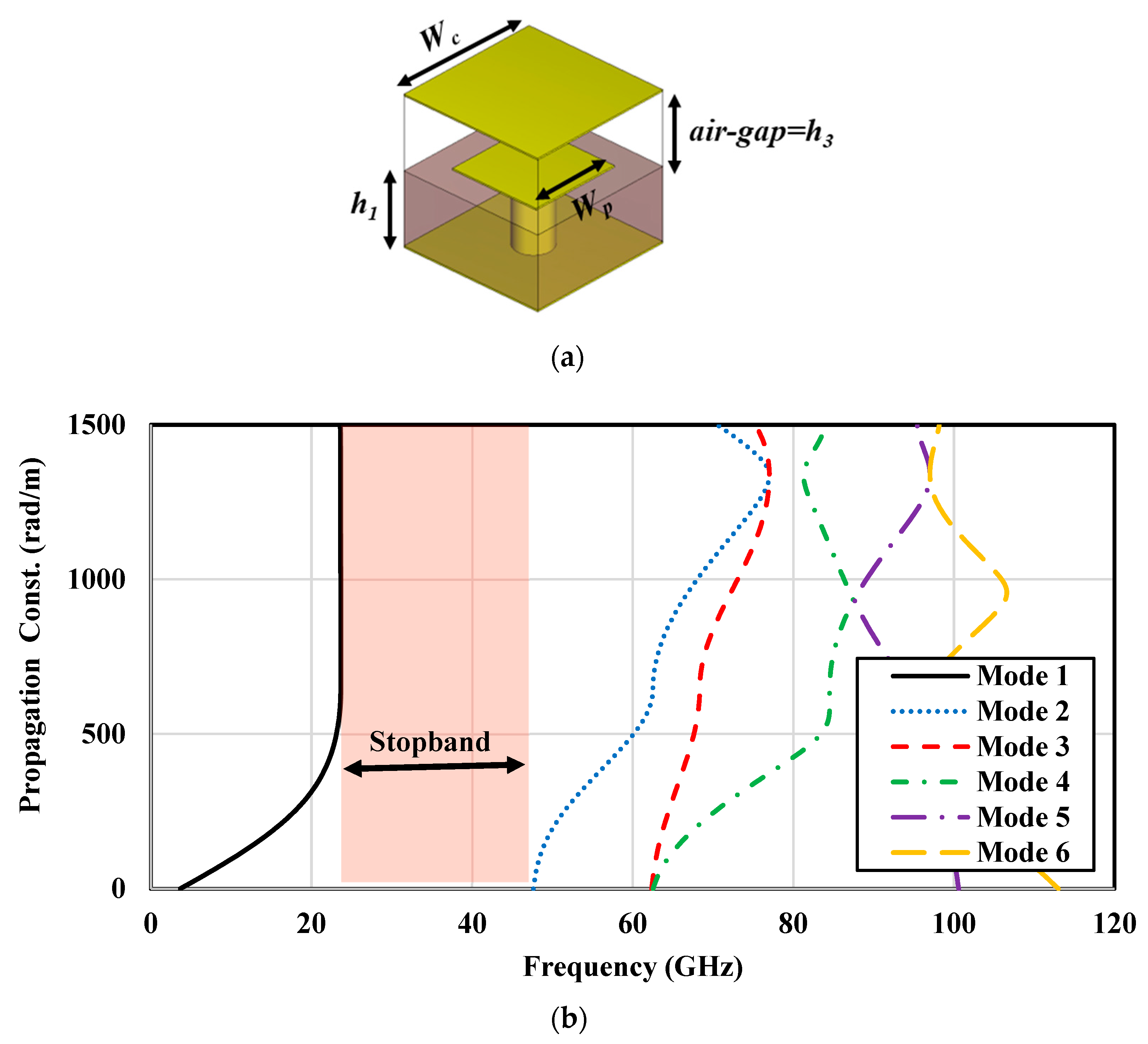
2.1. Printed Ridge Gap Waveguide Design

The low-loss PRGW is formed by periodic mushroom-like unit cells printed on the RT3003 substrate acting as electromagnetic bandgap (EBG) cells that are connected to the ground plane through metalized vias [48,49]. The periodic arrangement of EBG unit cells functions as an Artificial Magnetic Conductor (AMC) surface, which emulates Perfect Magnetic Conductor (PMC) behavior across a specific frequency bandwidth. By maintaining an air gap height smaller than λ/4, electromagnetic waves (EMs) can propagate between the upper ground plane and the ridge. This configuration effectively suppresses wave propagation outside the ridge between the AMC and the ground plane, creating a distinct stopband. The dimensions of an EBG unit cell and its dispersion, which is obtained using the computer simulation technology (CST) (Eigen-mode solver), are depicted in Figure 2. This analysis reveals a propagation constant of zero at frequencies between 24 GHz and 48 GHz, highlighting a critical frequency range for operational effectiveness. The unit cell is designed with a square shape to simplify the engineering process, enhancing the ease of integration and design consistency in practical applications [50].

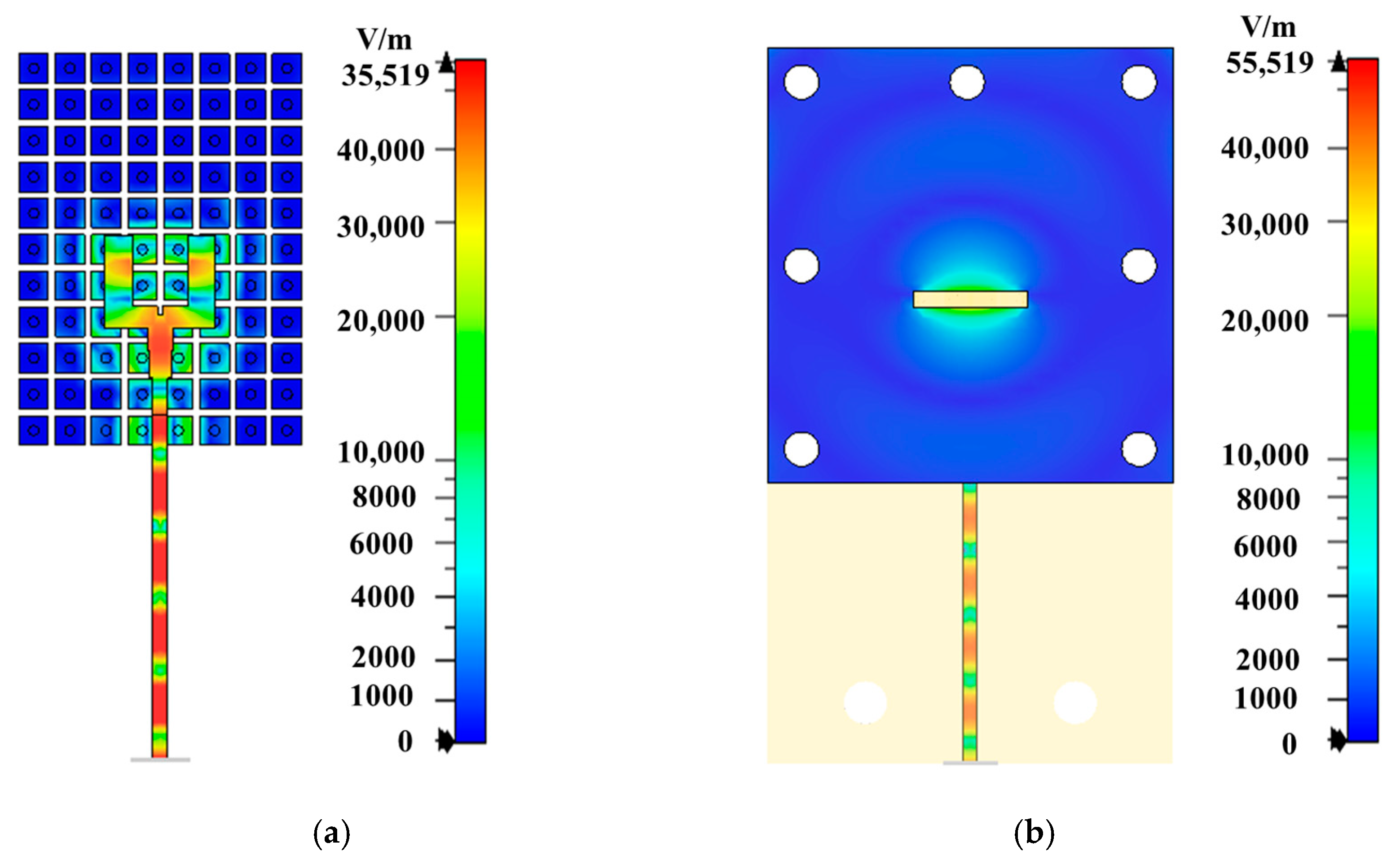
2.2. Operating Principle

Figure 3 shows the E-field distribution in the fork-shaped feed network and around the radiating slot, clearly demonstrating that the signal is transferred from the transition line to two equal signals of the fork-shaped ridge-line without any leakage from the feeding line and the field is confined along the ridge-line feeding the slot antenna with maximum radiation. The final layer of the Rogers RT 3003 substrate, which has a thickness of hm = 1.524 mm and serves as the radiation layer, consists of four horizontally oriented defected square patches. These patches are connected to the ground plane through vertical metallic vias. Each pair of grounded horizontal patches functions as a planar electric dipole (E-dipole), while the aperture between the patches serves as a magnetic dipole (M-dipole). The ME-dipole antenna operates by simultaneously exciting these magnetic and electric dipoles through the slot thereby generating the ME-dipole mode with linear polarization (LP) [51,52].
To achieve the desired CP performance, a narrow strip with a width of 0.8 mm connects the two inner corners of the diagonal patches, forming a bridge over the slot. Additionally, the corners of the other two defected patches are cut, as depicted in Figure 1c. This configuration allows for the energy from the exciting slot to be coupled and excites another mode of ME-dipole in the orthogonal direction. By optimizing the dimensions of the horizontal defected patches and apertures, a 90° phase difference between the two modes is achieved, which is necessary to generate CP radiation. Figure 4 clearly shows how the current, after radiation from the dipole antenna, is rotated, confirming the circular polarization performance of the designed antenna at 28 GHz.
To clarify the operating principle of the designed CP antenna, the simulated surface current distributions over the ME-dipole antenna are illustrated in Figure 5. These distributions are shown at the operating frequency of 28 GHz over a period of (T).
From Figure 5, it can be observed that at time t = 0 and t = T/2, the surface current distributions are directed along the y-direction and x-direction on the horizontal patches and the vertical vias, respectively. That indicates that the electric dipole in the y-direction and the magnetic dipole in the x-direction are excited at the same time. In addition, at t = T/4 and t = 3T/4 the direction of the surface current distributions changes by 90o. This means that the magnetic dipole is excited in the y-direction while the electric dipole is excited in the x-direction. Moreover, it is evident that as the time t increases from 0 to 3T/4, the surface current rotates clockwise, resulting in LHCP radiation.

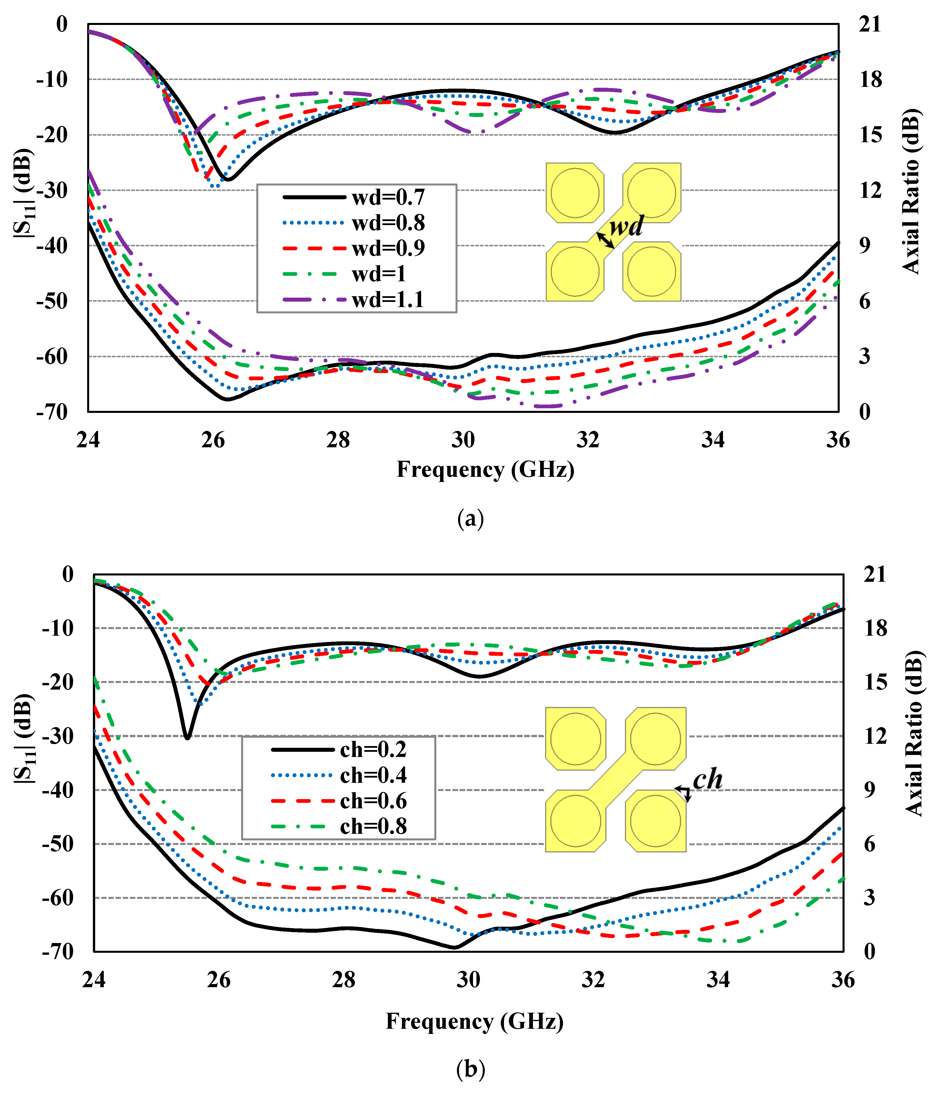
2.3. Parametric Study

To better understand how various geometrical parameters of the ME-dipole antenna enhance the performance of the CP antenna, a series of parametric studies were conducted. These studies focused on the impact of critical parameters, such as strip thickness (wd), cut depth of horizontal patches (ch), and width of the horizontal patches (dp), on the reflection coefficient (|S11|) and AR. Each parameter was varied while keeping the others at their optimized values, as listed in Table 1.
Figure 6a presents the simulated results for |S11| and AR at different widths of the middle diagonal strip connecting the two defected patches (wd), ranging from 0.7 to 1.1 mm. It is observed that increasing wd shifts the impedance and AR bandwidth to higher frequencies.
Figure 6b illustrates the effect of increasing the cut depth of horizontal patches (ch) from 0.2 to 0.8 mm, which significantly shifts the AR bandwidth to higher frequencies while maintaining a relatively stable |S11|.
Finally, Figure 6c displays the simulation results for |S11| and AR at different widths of the horizontal patches (dp). Adjusting dp from 1.85 to 2.15 mm improves the AR performance and shifts it to lower frequencies, resulting in a better |S11| match.

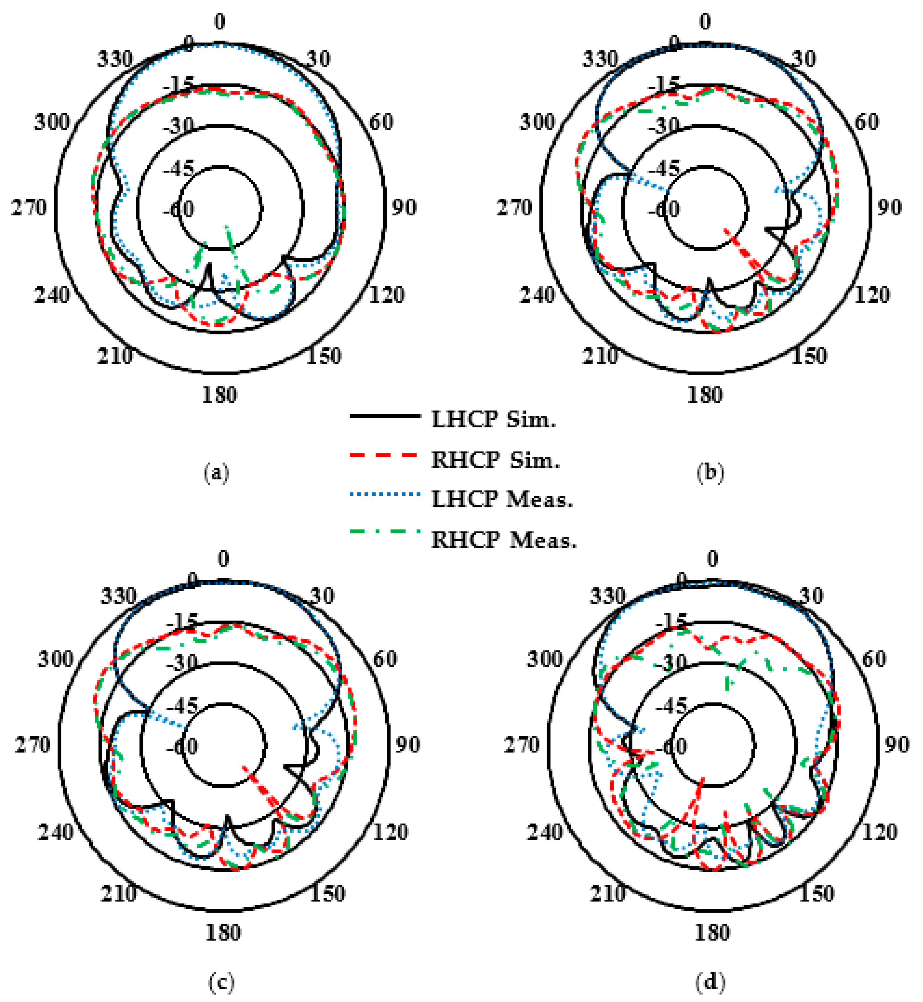
3. Experimental Validation

A prototype was fabricated to experimentally validate the performance of the designed CP antenna. Figure 7 shows the photographs of the fabricated prototype, which was assembled by fabricating each layer separately and then joining them using multiple plastic screws (M2). The 50 Ω microstrip line on the third layer was extended to connect a 2.92 mm (K) end-launch connector.
To ensure the accuracy of the experimental results, two prototypes were fabricated. The first prototype, shown in Figure 7, was assembled using screws to connect the layers, ensuring a tightly secured structure. In the second prototype, the layers were glued together under pressure in a machine setup. However, this process may have caused slight bending of the layers due to the applied pressure, which could have slightly affected the characteristics of the antenna. While the measurement results from both prototypes were close, the first prototype showed slightly better performance and matched the simulation results more closely. This is likely due to the controlled assembly method in the first prototype, which avoided the potential deformation caused by the gluing process. As a result, we relied on the measurements from the first prototype for the final results presented in this paper.
Additionally, the radiation measurements were conducted in an antenna chamber designed for accurate far-field testing. The chamber provided a controlled environment, free from external interference, ensuring reliable results that accurately reflect the performance of the antenna under ideal conditions, as shown in Figure 7b.
The simulated and experimental reflection coefficients shown in Figure 8 are in good agreement, although there may be minor differences due to assembly and fabrication errors. The Agilent 8722ES Vector Network Analyzer was used to measure the reflection coefficient characteristics, confirming that the designed CP antenna is well matched (for |S11| below −10 dB) for a wideband impedance bandwidth of approximately 31.0%, ranging from 25.24 to 34.5 GHz. Figure 9 presents the simulated and experimental peak gain and AR of the proposed CP antenna, demonstrating the measured peak gains of about 7.8 and 6.65 dBic at 28 and 32 GHz, respectively. Further, the designed CP antenna has a 3 dB AR bandwidth wider than 24.9%, ranging from 26.40 to 33.91 GHz. The normalized simulated and experimental co-polarization (LHCP) and cross-polarization (RHCP) radiation patterns of the antenna are plotted in Figure 10 at two operating frequencies, 28 and 32 GHz, in both xoz- and yoz-planes. It can be observed that the designed CP antenna radiates as an LHCP antenna with a stable directional radiation pattern in the +z direction. On both xoz- and yoz-planes for both frequencies (28 and 32 GHz), the isolation between co- and cross-polarizations is over 15 dB in the broadside direction. The radiation and total efficiencies of the CP antenna are depicted in Figure 11. The antennas, which are fed by PRGW technology, exhibit efficiencies better than 96%. This high-efficiency is attributed to the minimal transmission losses characteristic of PRGW technology at high frequencies.

4. Discussion

To highlight the superiority of the presented antenna performance, a comparison with other reported CP antennas designed by different feed network technologies is summarized in Table 2. Low-cost PCB technology was used in all listed planar antennas for the advantage of easy integration and fabrication at high frequencies. In [12], a ME-dipole antenna using a meta-surface was utilized to improve the gain and the radiation efficiency of the antenna but suffered from narrow impedance and AR bandwidths. The CP antenna in [17] produced a wide impedance bandwidth, but the gain of the antenna was low and had the problem of a bulky profile due to the usage of the spiral antenna. The impedance and AR bandwidths of the CP antenna based on PRGW technology reported in [18] were not wide enough. Compared to the SIW-fed CP ME-dipole antennas in [29,30,51], the proposed antennas fed by PRGW obtain greater efficiencies, more than 96%, because of minimal transmission losses at high frequencies. In summary, the results emphasize that the designed low-profile and high-performance CP antenna in terms of wider impedance and 3 dB AR bandwidths as well as acceptable gain is a potential candidate for the next-generation mm-wave communications with CP capabilities.

5. Conclusions

A planar CP ME-dipole antenna was proposed in this section for mm-wave wideband applications operating at Ka-band. The ME-dipole antenna was excited by a transverse narrow slot that was coupled to a fork-shaped low-loss PRGW feed network. To achieve CP performance, an additional metallic strip was introduced to connect the inner corners of the defective patches by creating two orthogonal modes with similar amplitudes and a 90◦ phase difference. The fabricated antenna demonstrates excellent CP performance, including wide impedance and AR bandwidths of 31% and 24.9%, respectively. An experimental peak gain of 7.8 dBic at 28 GHz was also achieved. The results demonstrate superiority over similar works. With these features, the proposed antenna is an attractive candidate for future 5G applications due to its wideband and low-loss capabilities.

Author Contributions

Conceptualization, Z.M. and M.M.M.A.; methodology, Z.M.; software, Z.M. and M.M.M.A.; validation, Z.M., M.M.M.A. and T.A.D.; formal analysis, Z.M. and M.M.M.A.; investigation, Z.M.; resources, Z.M., M.M.M.A., P.P., P.F. and T.A.D.; data curation, Z.M. and M.M.M.A.; writing—original draft preparation, Z.M.; writing—review and editing, Z.M., M.M.M.A. and P.P.; supervision, T.A.D. All authors have read and agreed to the published version of the manuscript.

Funding

This research received no external funding.

Institutional Review Board Statement

Not applicable.

Informed Consent Statement

Not applicable.

Data Availability Statement

The data presented in this study are openly available.

Acknowledgments

This research was supported by FRQNT.

Conflicts of Interest

The authors declare no conflicts of interest.

References

  1. Rangan, S.; Rappaport, T.S.; Erkip, E. Millimeter-Wave Cellular Wireless Networks: Potentials and Challenges. Proc. IEEE 2014, 102, 366–385. [Google Scholar] [CrossRef]
  2. Kakhki, M.B.; Dadgarpour, A.; Antoniades, M.A.; Sebak, A.R.; Denidni, T.A. Magneto-Electric Dipole Antennas Loaded with Meta-Lens for 5G MIMO Pattern Diversity Applications. IEEE Trans. Antennas Propag. 2022, 70, 7112–7117. [Google Scholar] [CrossRef]
  3. Mousavirazi, Z.; Harifi-Mood, M.; Ali, M.M.M.; Tatu, S.O.; Denidni, T.A. Wideband Miniaturized Multi-Port Correlator for 5G Applications at 28 GHz. In Proceedings of the 2022 IEEE International Symposium on Antennas and Propagation and USNC-URSI Radio Science Meeting (AP-S/URSI), Denver, CO, USA, 10–15 July 2022; pp. 1052–1053. [Google Scholar]
  4. Ohmori, S.; Yamao, Y.; Nakajima, N. The Future Generations of Mobile Communications Based on Broadband Access Technologies. IEEE Commun. Mag. 2000, 38, 134–142. [Google Scholar]
  5. Mousavi, Z.; Rezaei, P. Millimetre-Wave Beam-Steering Array Antenna by Emphasising on Improvement of Butler Matrix Features. IET Microw. Antennas Propag. 2019, 13, 1287–1292. [Google Scholar] [CrossRef]
  6. Rappaport, T.S.; Sun, S.; Mayzus, R.; Zhao, H.; Azar, Y.; Wang, K.; Wong, G.N.; Schulz, J.K.; Samimi, M.; Gutierrez, F. Millimeter Wave Mobile Communications for 5G Cellular: It Will Work! IEEE Access 2013, 1, 335–349. [Google Scholar] [CrossRef]
  7. Bhargava, V. Millimetre Wave Bands for 5G Wireless Communications. In Proceedings of the 2014 International Workshop on High Mobility Wireless Communications, Beijing, China, 1–3 November 2014; p. 2-2. [Google Scholar]
  8. Al-Falahy, N.; Alani, O.Y.K. Millimetre Wave Frequency Band as a Candidate Spectrum for 5G Network Architecture: A Survey. Phys. Commun. 2019, 32, 120–144. [Google Scholar] [CrossRef]
  9. Mohapatra, S.K.; Swain, B.R.; Pati, N.; Pradhan, A. Road Towards Mili Meter Wave Communication For 5G Network: A Technological Overview. Trans. Mach. Learn. Artif. Intell. 2014, 2, 48–60. [Google Scholar] [CrossRef]
  10. Al-Alem, Y.; Kishk, A.A. Simple High Gain 60 GHz Antenna. In Proceedings of the 2018 IEEE International Symposium on Antennas and Propagation & USNC/URSI National Radio Science Meeting, Boston, MA, USA, 8–13 July 2018; pp. 1693–1694. [Google Scholar]
  11. Baghernia, E.; Ali, M.M.M.; Sebak, A.R. 2 × 2 Slot Spiral Cavity-Backed Antenna Array Fed by Printed Gap Waveguide. IEEE Access 2020, 8, 170609–170617. [Google Scholar] [CrossRef]
  12. Dadgarpour, A.; Sorkherizi, M.S.; Kishk, A.A. High-Efficient Circularly Polarized Magnetoelectric Dipole Antenna for 5G Applications Using Dual-Polarized Split-Ring Resonator Lens. IEEE Trans. Antennas Propag. 2017, 65, 4263–4267. [Google Scholar] [CrossRef]
  13. Mousavi Razi, Z.; Rezaei, P.; Valizade, A. A Novel Design of Fabry-Perot Antenna Using Metamaterial Superstrate for Gain and Bandwidth Enhancement. AEU Int. J. Electron. Commun. 2015, 69, 1525–1532. [Google Scholar] [CrossRef]
  14. Ali, M.M.M.; Al-Hasan, M.; Ben Mabrouk, I.; Denidni, T.A. Ultra-Wideband Hybrid Magneto-Electric Dielectric-Resonator Dipole Antenna Fed by a Printed RGW for Millimeter-Wave Applications. IEEE Access 2022, 10, 2028–2036. [Google Scholar] [CrossRef]
  15. Briqech, Z.; Sebak, A.R.; Denidni, T.A. Low-Cost Wideband mm-Wave Phased Array Using the Piezoelectric Transducer for 5G Applications. IEEE Trans. Antennas Propag. 2017, 65, 6403–6412. [Google Scholar] [CrossRef]
  16. Mousavirazi, Z.; Rafiei, V.; Denidni, T.A. Beam-Switching Antenna Array with Dual-Circular-Polarized Operation for WiMAX Applications. AEU Int. J. Electron. Commun. 2021, 137, 153796. [Google Scholar] [CrossRef]
  17. Baghernia, E.; Movahedinia, R.; Sebak, A.R. Broadband Compact Circularly Polarized Spiral Antenna Array Fed by Printed Gap Waveguide for Millimeter-Wave Applications. IEEE Access 2021, 9, 86–95. [Google Scholar] [CrossRef]
  18. Ali, M.M.M.; Sebak, A. Printed RGW Circularly Polarized Differential Feeding Antenna Array for 5G Communications. IEEE Trans. Antennas Propag. 2019, 67, 3151–3160. [Google Scholar] [CrossRef]
  19. Mousavi, Z.; Rezaei, P.; Rafii, V. Single Layer CPSSA Array with Change Polarization Diversity in Broadband Application. Int. J. RF Microw. Comput. Aided Eng. 2017, 27, e21075. [Google Scholar] [CrossRef]
  20. Melouki, N.; Hocini, A.; Fegriche, F.Z.; PourMohammadi, P.; Naseri, H.; Iqbal, A.; Denidni, T.A. High-Gain Wideband Circularly Polarised Fabry–Perot Resonator Array Antenna Using a Single-Layered Pixelated PRS for Millimetre-Wave Applications. Micromachines 2022, 13, 1658. [Google Scholar] [CrossRef]
  21. PourMohammadi, P.; Fei, P.; Nasseri, H.; Zheng, Q.; Babarinde, O.J.; Volski, V.; Vandenbosch, G.A.E.; Denidni, T.A. A Single-Layer Compact Wideband Circularly Polarized Patch Array for 5G Communications. IEEE Antennas Wirel. Propag. Lett. 2023, 22, 754–758. [Google Scholar] [CrossRef]
  22. Mousavirazi, Z.; Denidni, T.A. A Circularly-Polarized Antenna for 5G Applications Fed by Printed Ridge-Gap Waveguide. In Proceedings of the 2021 IEEE 19th International Symposium on Antenna Technology and Applied Electromagnetics (ANTEM), Winnipeg, MB, Canada, 8–11 August 2021; pp. 1–2. [Google Scholar]
  23. Zheng, Q.; Ma, J.; Wu, Z.; PourMohammadi, P. Dual-Broadband High-Isolation Circularly Polarized Low-RCS Shared-Aperture Antenna Array Based on Mushroom-Type Metasurface. Opt. Commun. 2025, 574, 131127. [Google Scholar] [CrossRef]
  24. Liu, Y.; Liang, X.; Zhang, X.; Li, J.; Geng, J.; Jin, R.; Zhang, L. A K-Band Broadband Circularly Polarized Slot Antenna Based on L-Shaped Waveguide Cavity. IEEE Antennas Wirel. Propag. Lett. 2021, 20, 1606–1610. [Google Scholar] [CrossRef]
  25. Lam, K.Y.; Luk, K.M.; Lee, K.F.; Wong, H.; Ng, K.B. Small Circularly Polarized U-Slot Wideband Patch Antenna. IEEE Antennas Wirel. Propag. Lett. 2011, 10, 87–90. [Google Scholar] [CrossRef]
  26. Yu, Z.-Y.; Zhang, Y.-H.; He, S.-Y.; Gao, H.-T.; Chen, H.-T.; Zhu, G.-Q. A Wide-Angle Coverage and Low Scan Loss Beam Steering Circularly Polarized Folded Reflectarray Antenna for Millimeter-Wave Applications. IEEE Trans. Antennas Propag. 2022, 70, 2656–2667. [Google Scholar] [CrossRef]
  27. Liu, C.; Guo, Y.X.; Bao, X.; Xiao, S.Q. 60-GHz LTCC Integrated Circularly Polarized Helical Antenna Array. IEEE Trans. Antennas Propag. 2012, 60, 1329–1335. [Google Scholar] [CrossRef]
  28. Baghernia, E.; Sebak, A.R. Gain Enhancement of Wideband Millimeter-Wave Circularly Polarized Antenna Based on FSS Superstrate. In Proceedings of the 2021 IEEE 19th International Symposium on Antenna Technology and Applied Electromagnetics (ANTEM), Winnipeg, MB, Canada, 8–11 August 2021; pp. 1–2. [Google Scholar]
  29. Feng, B.; Lai, J.; Chung, K.L.; Chen, T.-Y.; Liu, Y.; Sim, C.-Y.-D. A Compact Wideband Circularly Polarized Magneto-Electric Dipole Antenna Array for 5G Millimeter-Wave Application. IEEE Trans. Antennas Propag. 2020, 68, 6838–6843. [Google Scholar] [CrossRef]
  30. Wu, S.; Zhao, J.; Xu, J. A Circularly Polarized Low-Profile Magnetoelectric Dipole Antenna. Microw. Opt. Technol. Lett. 2021, 63, 2852–2858. [Google Scholar] [CrossRef]
  31. Zhang, L.; Wu, K.; Wong, S.W.; He, Y.; Chu, P.; Li, W.; Wan, K.X.; Gao, S. Wideband High-Efficiency Circularly Polarized SIW-Fed S-Dipole Array for Millimeter-Wave Applications. IEEE Trans. Antennas Propag. 2020, 68, 2422–2427. [Google Scholar] [CrossRef]
  32. Zhu, C.; Xu, G.; Ding, D.; Wu, J.; Wang, W.; Huang, Z.X.; Wu, X.L. Low-Profile Wideband Millimeter-Wave Circularly Polarized Antenna with Hexagonal Parasitic Patches. IEEE Antennas Wirel. Propag. Lett. 2021, 20, 1651–1655. [Google Scholar] [CrossRef]
  33. Zhang, L.; Gao, S.; Luo, Q.; Young, P.R.; Li, Q.; Geng, Y.L.; Abd-Alhameed, R.A. Single-Feed Ultra-Wideband Circularly Polarized Antenna with Enhanced Front-to-Back Ratio. IEEE Trans. Antennas Propag. 2016, 64, 355–360. [Google Scholar] [CrossRef]
  34. Dai, X.; Wu, G.B.; Luk, K.M. A Wideband Circularly Polarized Transmitarray Antenna for Millimeter-Wave Applications. IEEE Trans. Antennas Propag. 2023, 71, 1889–1894. [Google Scholar] [CrossRef]
  35. Mousavirazi, Z.; Ali, M.M.M.; Denidni, T.A. Millimeter-Wave High Gain Hybrid ME-DRD Antenna Fed by PRGW Technology. In Proceedings of the 2022 IEEE International Symposium on Antennas and Propagation and USNC-URSI Radio Science Meeting (AP-S/URSI), Denver, CO, USA, 10–15 July 2022; pp. 9–10. [Google Scholar]
  36. Tan, Q.; Fan, K.; Yu, W.; Wang, W.; Liu, L.; Luo, G.Q. A Circularly Polarized Magneto-Electric Dipole Antenna Array with Wide AR and Impedance Bandwidth for Millimeter-Wave Applications. IEEE Antennas Wirel. Propag. Lett. 2023, 22, 2250–2254. [Google Scholar] [CrossRef]
  37. Mousavirazi, Z.; Rafiei, V.; Ali, M.M.M.; Denidni, T.A. Wideband and Low-Loss Magneto-Electric Dipole Antenna Fed by Printed Ridge-Gap Waveguide Technology. In Proceedings of the 2021 IEEE 19th International Symposium on Antenna Technology and Applied Electromagnetics (ANTEM), Winnipeg, MB, Canada, 8–11 August 2021; pp. 1–2. [Google Scholar]
  38. Askari, H.; Hussain, N.; Sufian, M.A.; Lee, S.M.; Kim, N. A Wideband Circularly Polarized Magnetoelectric Dipole Antenna for 5G Millimeter-Wave Communications. Sensors 2022, 22, 2338. [Google Scholar] [CrossRef] [PubMed]
  39. Shi, B.; Cao, X.; Deng, C. Wideband Circularly Polarized Magneto-Electric Dipole Antenna Array with Metallic Walls for Millimeter-Wave Applications. Electronics 2023, 12, 2154. [Google Scholar] [CrossRef]
  40. Tian, Y.; Ouyang, J.; Hu, P.F.; Pan, Y. Millimeter-Wave Wideband Circularly Polarized Endfire Planar Magneto-Electric Dipole Antenna Based on Substrate Integrated Waveguide. IEEE Antennas Wirel. Propag. Lett. 2022, 21, 49–53. [Google Scholar] [CrossRef]
  41. Alfonso, E.; Kildal, P.-S.; Valero-Nogueira, A.; Baquero, M. Study of the Characteristic Impedance of a Ridge Gap Waveguide. In Proceedings of the 2009 IEEE Antennas and Propagation Society International Symposium, North Charleston, SC, USA, 1–5 June 2009; pp. 1–4. [Google Scholar]
  42. Kildal, P.; Zaman, A.; Rajo-Iglesias, E. Design and Experimental Verification of Ridge Gap Waveguides in Bed of Nails for Parallel Plate Mode Suppression. IET Microw. Antennas Propag. 2011, 5, 262–270. [Google Scholar] [CrossRef]
  43. Rajo-Iglesias, E.; Zaman, A.U.; Alfonso, E.; Kildal, P.-S. Alternative Ridge Gap Waveguide Design Using a Mushroom-Type EBG Surface. In Proceedings of the 2009 IEEE Antennas and Propagation Society International Symposium, North Charleston, SC, USA, 1–5 June 2009; pp. 1–4. [Google Scholar]
  44. Jiang, Z.X.; Han, K.; Deng, Z.L.; Huang, G.L. Wideband Dual Circularly Polarized Substrate-Integrated Cavity Antenna Array for Millimeter-Wave Applications. IEEE Antennas Wirel. Propag. Lett. 2024, 23, 2777–2781. [Google Scholar] [CrossRef]
  45. Xu, H.; Mao, Z.; Yu, Y.; Wei, P.; Yang, J.; Yu, Z. Millimeter-Wave Wideband Circularly Polarized SIW Cavity-Backed Stacked Dipole Array Antenna. IEEE Antennas Wirel. Propag. Lett. 2024, 23, 838–842. [Google Scholar] [CrossRef]
  46. Diman, A.A.; Karami, F.; Rezaei, P.; Amn-e-Elahi, A.; Mousavirazi, Z.; Denidni, T.A.; Kishk, A.A. Efficient SIW-Feed Network Suppressing Mutual Coupling of Slot Antenna Array. IEEE Trans. Antennas Propag. 2021, 69, 6058–6063. [Google Scholar] [CrossRef]
  47. Cao, J.Y.; Wang, H.; Mou, S.X.; Soothar, P.; Zhou, J.W. An Air Cavity-Fed Circularly Polarized Magneto-Electric Dipole Antenna Array with Gap Waveguide Technology for mm-Wave Applications. IEEE Trans. Antennas Propag. 2019, 67, 6211–6216. [Google Scholar] [CrossRef]
  48. Mousavirazi, Z.; Akbari, M.; Denidni, T.A. Millimeter-Wave High-Gain PRGW Antenna Using a Fabry-Perot Cavity. In Proceedings of the 2020 IEEE International Symposium on Antennas and Propagation and North American Radio Science Meeting, Montreal, QC, Canada, 5–10 July 2020; pp. 1365–1366. [Google Scholar]
  49. Ali, M.M.M.; Mousavirazi, Z.; Naseri, H.; Denidni, T.A. Design of Low-Loss Printed Ridge-Gap-Waveguide Crossover for Millimeter-Wave Applications. In Proceedings of the 2022 IEEE International Symposium on Antennas and Propagation and USNC-URSI Radio Science Meeting (AP-S/URSI), Denver, CO, USA, 10–15 July 2022; pp. 547–548. [Google Scholar]
  50. Mousavirazi, Z.; Ali, M.M.M.; Gheisanab, H.N.; Denidni, T.A. Analysis and Design of Ultra-Wideband PRGW Hybrid Coupler Using PEC/PMC Waveguide Model. Sci. Rep. 2022, 12, 14214. [Google Scholar] [CrossRef]
  51. Li, Y.; Luk, K.-M. A 60-GHz Wideband Circularly Polarized Aperture-Coupled Magneto-Electric Dipole Antenna Array. IEEE Trans. Antennas Propag. 2016, 64, 1325–1333. [Google Scholar] [CrossRef]
  52. Kakhki, M.B.; Dadgarpour, A.; Antoniades, M.A.; Sebak, A.R.; Denidni, T.A. Dual Complementary Source Magneto-Electric Dipole Antenna Loaded with Split Ring Resonators. IEEE Access 2020, 8, 59351–59361. [Google Scholar] [CrossRef]
Figure 1. (a) The perspective view of the exploded CP antenna, (b) the top view of the fork-shaped feed network, and (c) the top view of the ME-dipole.
Sensors 24 08183 g001aSensors 24 08183 g001b
Figure 2. (a) Configuration and (b) dispersion diagram of proposed square PRGW unit cell.
Sensors 24 08183 g002
Figure 3. The simulated E-field distribution (a) of the fork-shaped feed network and (b) around the radiating slot.
Sensors 24 08183 g003
Figure 4. The rotation surface currents in the antenna.
Sensors 24 08183 g004
Figure 5. The simulated current distributions over the ME-dipole antenna at a period of T for (a) t = 0, (b) t = T/4, (c) t = T/2, and (d) t = 3T/4.
Sensors 24 08183 g005
Figure 6. The simulated |S11| and AR of the designed CP antenna for (a) wd, (b) ch, and (c) dp (unit: mm).
Sensors 24 08183 g006aSensors 24 08183 g006b
Figure 7. Photographs of fabricated CP PRGW ME-dipole antenna: (a) fabricated prototype and (b) far-field measurement setup.
Sensors 24 08183 g007
Figure 8. The simulated and measured reflection coefficient (|S11|) of the designed CP antenna.
Sensors 24 08183 g008
Figure 9. The simulated and measured peak gain and axial ratio of the designed CP antenna.
Sensors 24 08183 g009
Figure 10. The simulated and measured normalized LH/RHCP radiation pattern of the CP PRGW ME-dipole antenna in the xoz plane at (a) 28 GHz and (b) 32 GHz, and in the yoz plane at (c) 28 GHz and (d) 32 GHz.
Sensors 24 08183 g010
Figure 11. The simulated efficiency of the CP PRGW ME-dipole antenna.
Sensors 24 08183 g011
Table 1. Optimized dimensions of proposed CP ME-dipole antenna (units: mm).
Parametersh1h2h3hmlswswf
Values (mm)0.7620.2540.2541.5245.20.71.13
Parameterslt1wt1lt2wt2lt3wt3ts
Values (mm)3.090.631.160.960.921.10.2
ParametersdpchlfwdWpWcAir gap
Values (mm)2.050.43.890.81.231.50.254
Table 2. Performance comparison between CP antenna configurations.
Ref.Frequency (GHz)Antenna TypeFeen Network TechnologyImpedance BW (−10 dB)3dB ARBWGain (dBic)
[12]28ME-dipolePRGW24.24%7.4%10.7
[17]34SpiralPRGW37.2%23.2%7.2
[18]28AperturePRGW15.6%10%9
[29]28ME-dipoleSIW24.2%16.5%-
[30]25ME-dipoleSIW32.6%12.8%7.8
[51]60ME-dipoleSIW28.8%25.9%9
This
work
28ME-dipolePRGW31.0%24.9%7.8
Disclaimer/Publisher’s Note: The statements, opinions and data contained in all publications are solely those of the individual author(s) and contributor(s) and not of MDPI and/or the editor(s). MDPI and/or the editor(s) disclaim responsibility for any injury to people or property resulting from any ideas, methods, instructions or products referred to in the content.

