Abstract
Runway surface friction is critically important to safe aircraft operations and mostly depends on the surface texture, which provides grip in the presence of contamination and directly affects the friction coefficient in general. Microtexture assessment is the most challenging part of texture assessment since there is no standardised pavement microtexture control method in runway maintenance and management practice. The purpose of this study was to develop a simple laser profilometer and analysis model and subsequent validation for use in runway friction surveys. To that end, a simple laser profilometer was developed, and a profile picture analysis and macrotexture filtration method were designed. Test results were compared to the stylus-based roughness tester and the British Pendulum Tester. The proposed profile picture analysis and profile smothering and filtration methodology, based on linear approximation, is simpler and more effective for the case of macrotexture filtration for the friction survey. The laser profilometer model results were highly correlated with the stylus-based roughness tester results (R2 = 0.99). The average roughness of the microtexture profile, after smothering and macrotexture filtration, also showed good correlation with the British Pendulum results (R2 = 0.78). The results from this study confirm the possibility of texture assessment for routine runway friction surveys using a simple and economical laser profilometer, which is not routinely available in current airport surface friction management.
1. Introduction
Surface texture is a set of surface irregularities characterised by the size, depth and other shape parameters. It is usually divided into different classes, depending on the size of irregularities. This is important for the analysis of texture because all of the classes affect the rolling and sliding performance of the tire differently. As shown in Figure 1, the Permanent International Association of Road Congers (PIARC) defines four classes of texture: microtexture, macrotexture, megatexture and unevenness [1]. For practical purposes, only micro- and macrotextures are important for runway surface friction management due to the tire-pavement contact area being relatively small compared to megatexture and unevenness.
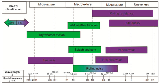
Figure 1.
PIARC classification for pavement surface characteristics according to wavelength [2].
The macrotexture of a runway surface mostly depends on the type of surface, being a mixture type, and maximum aggregate size. Open-graded asphalt mixes, stone mastic asphalt, and porous asphalt usually have a relatively high texture [3,4]. In contrast, dense-graded asphalt and cement concrete have lower macrotexture, and in most cases, special treatments are required to increase the actual or effective macrotexture [5,6]. Importantly, even when adequate macrotexture is provided at the time of surface constructure, it can be reduced due to contamination and wear of the pavement through the life of the surface [7]. Consequently, ongoing monitoring and measurement are required.
In contrast, the microtexture mostly depends on the parameters of the stone aggregate. Stone aggregate roughness can be different due to the size of the aggregate, its shape and its hardness. Crushed stone, for example, usually has a larger microtexture than rounded natural gravels [8]. The roughness of a stone can also change due to wear and erosion, a phenomenon known as aggregate polishing, with higher initial microtexture usually associated with a higher rate of microtexture wear during service [9]. Surface microtexture can also be reduced due to contamination and the “masking” effect when binder, rubber, clay, dust, or other contaminants fill the microtexture cavities and pores, reducing the microtexture [10,11]. In practice, it is common for microtexture to be revealed as the binder is worn off the exposed aggregate in a new surface [12], but then to be masked over time by rubber contamination from landing and taxiing aircraft tires [13].
Due to the evolution of both microtexture and macrotexture over the life of a runway surface, texture parameters require regular monitoring because of their impact on aircraft safety, surface durability and the associated environmental effects [14]. Although macrotexture measurements are simple and well established, with a number of recommended techniques available [2], microtexture measurements are not common and require improved standards and monitoring systems. For example, the International Civil Aviation Organisation (ICAO) does not currently recommend any microtexture measurement techniques. In their international regulation known as Annex 14 [15], it is recommended to provide a good microtexture. However, their guidance material, known as PANS Aerodromes [16], recommends only visual and tactile assessment of microtexture, which can only be used for the detection of contamination and defects.
In contrast to airport pavement practice, researchers have used different methods of microtexture assessment, which can be divided into contact and non-contact methods. Contact methods include the mechanical stylus test [17] and different wear tests [18]. Non-contact methods are more common and include laser profilometry [19], image texture analysis [20], stereoscopy [21], computer tomography scanning [22], 3D scanning [23] and simpler microscopy assessment methods, such as the straightedge shadow method [9,24]. The most precise and simple method is laser profilometry, which is based on the geometrical measurement of a projection of the laser beam on a surface [25]. Laser profilometry requires a profilometer, the main components of which are the laser and a camera (Figure 2), and data filtration and analyses software.
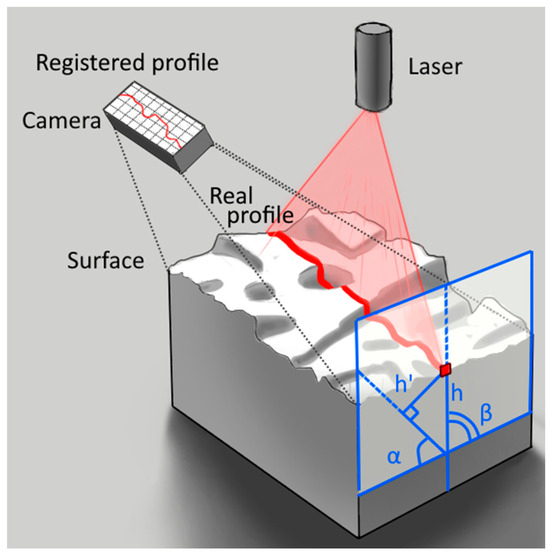
Figure 2.
Laser profilometer.
The relative height of the profile point on the surface and on the registered or measured profile shown in Figure 2 are related by Equation (1).
where h is a real height of the point on a profile, h′ is a height of the point on a registered profile, α is an angle between camera and surface and β is an angle between laser and surface.
Surface texture parameters can be separated into two-dimensional amplitude and shape-related parameters, three-dimensional amplitude and shape-related parameters, spectral characteristics of a surface wave and fractal and multifractal characteristics [2]. Amplitude and shape-related parameters are widely used during the texture assessment. However, the other parameters have limited use in regards to the texture analysis of pavement surfaces. In one study [26], macrotexture, obtained by a circular track meter, was characterised using wavelet analysis, which allowed the analysis of the influence of different aggregate sizes on surface texture. In a similar study [27], asphalt surface friction was characterised as a set of fractal parameters of texture. Fractal mathematics was also used for the texture analysis by Kikkalis et al. [28]. Besides that, fractal surface parameters can be effectively used for the surface topography analysis in material studies [29]. In this study, however, the surface texture for simplicity was characterised using the average roughness of a profile.
Various researchers have studied the influence of texture on available surface friction [30,31,32,33]. However, only a few of them have included microtexture measurements for the friction prediction (Table 1).

Table 1.
Correlation between friction and texture parameters in different studies.
Some of the abovementioned studies use theoretical models for friction calculations [36,37,39]. These studies are generally based on a hysteresis friction model [35]. This model also allows for the inclusion of contamination, such as water film thickness, using the same textural parameters, assuming that contamination acts as a filler for the texture and reduced the height of the asperities. Those models also showed good correlation with CFME data. A Persson model can also be combined with numerical analysis to calculate the stresses in the contact area and increase the reliability of the model [45]. However, practical use of those models is difficult since they require complex numerical analysis and a detailed survey of the surface texture, and it can be seen that the study based on the data obtained from field evaluation of the pavement parameters shows a lower accuracy than required [39].
In some of the more recent studies [42,43], artificial neural networks were used for friction prediction. An artificial neural network is a good tool for friction analysis, and it shows a high correlation between predicted and measured values for some pavements. However, one of the drawbacks of neural network models is that they work as a ‘black box’, since the calculation process is not presented for analysis. That creates a risk because the result is based mostly on the training process and some properties of materials used for training and not on fundamental dependencies [46].
Most of the abovementioned studies use 3D scanning for the microtexture measurements. That technique, however, requires expensive testing equipment and cannot be used widely in the field. Only three studies [36,38,44] used laser profilometry for microtexture assessment, with the equipment being different in all three cases. The parameters used in these studies were also different, which makes the comparison of the results difficult. Two of the studies [38,44] used linear models for the pavement friction prediction, the appropriateness of which also needs to be validated.
In general, recent research analysis shows that texture assessment can reliably predict surface friction, including the effect of contaminants on aircraft skid resistance. However, texture assessment methods are not fully developed within current international practice, and there is no friction model commonly used due to a lack of widely available microtexture assessment techniques of real runway pavement surfaces.
The aim of this study was to develop a simple and economical laser profilometer and to validate the potential to use that laser profilometer for surface texture characterisation and ultimately towards a unified microtexture assessment methodology, including microtexture profile analysis. For this purpose, the laser profilometry equipment was produced and verified against a standard roughness measurement device on plane surfaces before being assessed on real pavement surfaces against spot friction, measured by a British Pendulum machine.
2. Materials and Methods
2.1. Verification Surfaces
For the verification of the profilometer, a set of surfaces with minimal macrotexture was used. Those surfaces include sandpaper with P60, P80, P120, P180, and P240 grit, polished metal plates, and a mill file. A total of 8 samples were tested using a laser profilometer and roughness tester.
2.2. Validation Surfaces
For the microtexture and friction assessment, various surfaces were considered, including polished concrete (Figure 3c), rough concrete (Figure 3f), older asphalt (Figure 3e), road marking paint (Figure 3d), paving stones (Figure 3a,b), different grades of sandpaper (Figure 3g) and a smooth whiteboard (Figure 3h). The sandpaper and whiteboard were included to increase the range of the texture measured since all of the other surfaces had a generally similar microtexture. The sandpaper was secured to a heavy concrete slab using cyanoacrylate glue, to keep it flat and to avoid measurement errors. All of the tested surfaces had minimal macrotexture to avoid errors during the friction measurement. For this study, 17 total measurements were performed on surfaces with different microtexture values.
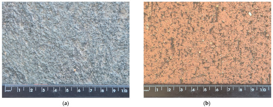
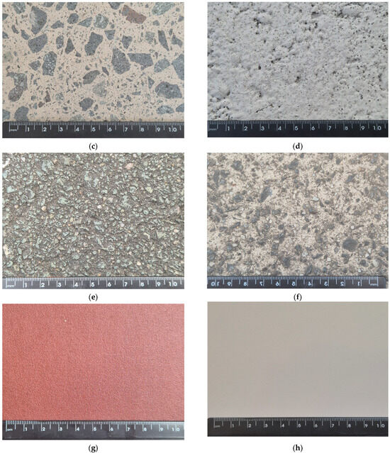
Figure 3.
Examples of tested surfaces: (a) natural paving stone, (b) ceramic paving stone, (c) polished concrete, (d) road marking, (e) asphalt, (f) rough concrete, (g) sandpapers and (h) whiteboard.
2.3. Friction Measurements
The British Pendulum machine was used for the friction measurements (Figure 4). This method is widely used for the friction measurement of different surfaces. This method is based on the measurement of the pendulum energy after sliding on a wet surface with the rubber slider on the end of the pendulum. The British Pendulum Number (BPN) is the unitless value shown on the plate behind the pendulum, reflecting the angle of the pendulum swing after sliding. For this study, measurements were performed on a wet surface. The reliability of the British Pendulum test has been shown to decrease with an increase in macrotexture [47]. Consequently, it is not recommended to use the British Pendulum on surfaces with a high macrotexture, such as sprayed seals and stone mastic asphalt.
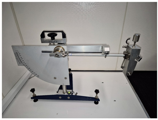
Figure 4.
British Pendulum machine.
2.4. Surface Texture Measurement
For the surface texture measurements, a simple laser profilometer was designed (Figure 5). Although laser profilometry is a well-known tool and there are commercial laser profilometers available, this study required a new model that was suitable for pavement surface measurement. The profilometer was also designed to be economical and small in size, allowing it to be used by many airports around the world. The profilometer mount allows the angles between the laser and the camera and pavement surface to be adjusted. The main advantages of the model, compared to commercial equipment, are the component price, which is equal to 36 AUD in total, excluding the price of the mount, which was made from the 3 mm sheet metal. There are no comparable commercially available products designed for the microtexture assessment of pavement surfaces, with similar equipment costing more than 1000 AUD [48].
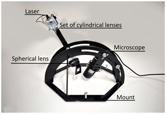
Figure 5.
Laser profilometer for microtexture assessment.
The horizontal resolution of the laser profilometer is equal to 6.09 µm. Vertical resolution can vary by changing the angle between the camera and the laser (1). The thickness of a laser beam is approximately 100 µm, but the real vertical resolution is finer due to the nature of the processing algorithm, as shown in the example in Figure 6.
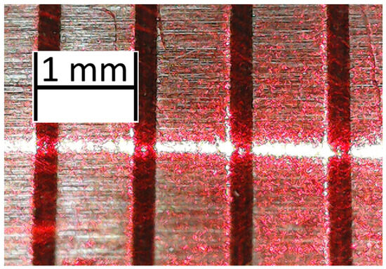
Figure 6.
Horizontal resolution of the laser profilometer.
Verification of the laser profilometer was performed using the Intra Touch roughness tester (Figure 7) with 4 nm vertical and 0.5 µm horizontal resolution. This roughness tester is based on the stylus test and allows precise texture measurement. The vertical range of that tester, however, is limited. Consequently, it is only possible to use it to measure the microtexture of plain surfaces with little or no macrotexture.
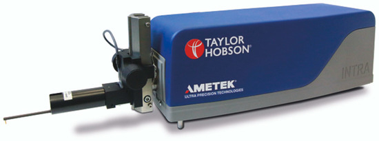
Figure 7.
Intra Touch roughness tester.
2.5. Data Processing
Once the surface profile is registered, it must be analysed. Consequently, a data processing algorithm was also designed. It consisted of the following four steps:
- Profile registration.
- Fine smothering.
- Macrotexture filtration.
- Texture parameters calculation.
The profile generated by the laser profilometer was first photographed with a phone-based camera. The photo was processed to obtain a texture profile. First, pixel brightness was calculated, as well as the profile line brightness threshold. After that, the points on the profile were calculated by finding the centre of brightness of each column of pixels. The registered profile was then smothered to remove any errors (Figure 8).
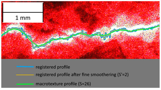
Figure 8.
Processing of the photo of a profile.
The obtained profile consists of macrotexture and microtexture. Macrotexture needs to be filtrated out for the microtexture analysis. There are many algorithms for macrotexture filtration, for example, the Fourier transformation, the Butterworth filter [49] and the Gaussian smoothing filter [43]. All of these can effectively isolate the microtexture from the macrotexture. However, the main drawback of those methods is they use orthogonal filtration, which can lead to microtexture overestimation. An example of that is shown in Figure 9. In this example, two different filtration algorithms were applied to the profile obtained by Florková et al. [50]. The existing algorithm was based on the Butterworth filter, and the microtexture depth was calculated as the height difference between the macrotexture and a point on a profile. A new algorithm was also applied that uses the distance between the point on a profile and the macrotexture profile. As shown in Figure 9 in a circle, the existing algorithm overestimates the microtexture. That overestimation affects zones near the slopes of macrotexture, and in the case of surfaces with deep macrotexture, that difference can be significant. For that reason, the new algorithm is justified for use with airport pavements, where it is crucial to provide a good macrotexture.
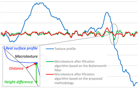
Figure 9.
Comparison of existing and proposed algorithms [50].
The macrotexture profile needs to be approximated based on the profile data for the filtration. Polynomial spline approximation is smoother than a linear approximation and can be used for mean profile approximation as well. However, for this study, the linear approximation was used for a number of reasons.
First, the polynomial spline is designed to “fit” the natural shape of the elastic beam, thus it can create an almost smooth profile [51]. The real profile or surface, however, is not limited by any force and can create an odd shape. Polynomial spline approximation can also lead to “overfitting”, which leads to an obvious error [52]. An example of overfitting is shown in Figure 10.
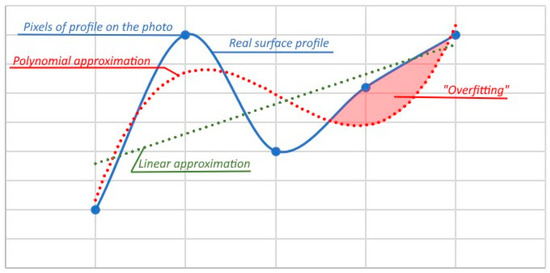
Figure 10.
Smoothening of the profile with linear and polynomial approximations.
Moreover, the friction problem requires an unusual solution for the profile approximation. For example, if you compare the flat surface and the surface with a curved shape, it is obvious that the grip is better on a curved surface. If we consider the flat surface to be the most slippery surface, we cannot use polynomial approximation for the smoothening of the surface. Otherwise, we will inevitably lower the overall predicted grip since we decided to characterise the grip by using the texture depth. An example of that is shown in Figure 11.
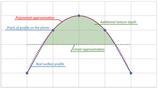
Figure 11.
Polynomial and linear approximations for the smoothening of the profile.
And finally, since the method in this study requires the calculation of the exact distance to the point, that problem is crucial for the acceptability of the filtration algorithm. With the polynomial approximation, it is hard to find the exact distance from any given point to the macrotexture profile. This problem can be solved using brute-force algorithms or using more advanced methods, such as the spherical clipping method [53]. All of the methods compute the approximate solution and require significant computational resources [54], especially in the case of the texture profiles, because the profile consists of thousands of points and the processing time can also become crucial. In the case of linear approximation, however, it is a simple problem with a simple solution, according to Equation (2).
where dn is a distance between the n-point (xn, yn) and the line defined by Equation (3).
where an and bn are coefficients of the line on a profile for each n-point.
In that case, the number of points for the linear approximation can be used as a filtration coefficient. The proposed algorithm finds a linear approximation based on the method of least squares for the (n − S; n + S) points for each n-point, where S is a filtration coefficient. The same algorithm is used for the fine smothering, with the number of points for linear approximation being equal to 2 × S′ + 1, where S′ is a fine smothering coefficient (Figure 8). Coefficients an and bn (2) for each point can be found using Equation (4) and Equation (5), respectively.
The same method can be used for the fine smothering. In the case of fine smothering, distance calculation is not important. Consequently, for simplicity, n-point coordinates (y′n, xn) of the point on a smothered profile can be calculated from Equation (6).
where a′n and b′n can be found for each point using Equation (4) and Equation (5), respectively, and using S′ coefficient instead of S.
Details of the profile registration algorithm and each further step are shown in Figure 12. This algorithm was applied using the Visual Basic application for Excel due to the simplicity of data storage and compatibility with other data analysis tools.
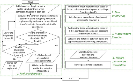
Figure 12.
Block diagram of microtexture profile analysis algorithm.
3. Results and Discussion
3.1. Laser Profilometer Verification
As stated above, the verification of the laser profilometer was performed using a stylus-based Intra Touch roughness tester (Figure 7). A sandpaper, smooth metal plate and a mill file were used as testing surfaces. Four sets of tests were performed with different laser and profilometer angles (Figure 2). The results are presented in Table 2. At the same time, the S′ coefficient was optimised to maximise the R2 value. The final S′ coefficient in all cases was 2.0. An average roughness (Ra) value was calculated in all cases without the macrotexture filtration.

Table 2.
Sets of tests for profilometer verification.
It was found that angle between camera and laser and surface affected the correlation between the roughness tester and laser profilometer results. The lower the angles, the higher the vertical resolution. However, too low an angle for the camera obstructs the vision of the asperities of macrotexture. Furthermore, too low an angle for the laser distorts the profile projection. The maximum correlation between the roughness tester and profilometer was obtained in the fourth series of tests, with both angles being set to 60°. The associated correlation is shown in Figure 13. Despite the high correlation indicating the profilometer is in fact valid, it can be seen that the resolution of the laser is lower than that of the Intra Tech roughness meter, because at average roughness (Ra) lower than 10 μm, the profilometer tends to underestimate the Intra Tech reported roughness. Despite this, the results are proportionally consistent for the two devices. This error for finer surfaces, however, will systematically occur for such laser profilometers. This problem, however, can generally be ignored for runway friction management due to the coarseness of pavement surfaces.
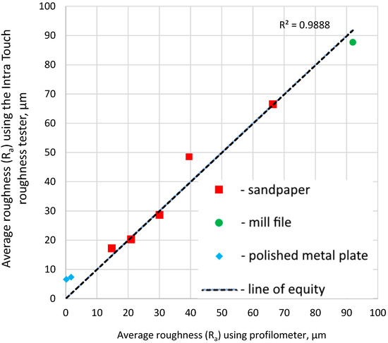
Figure 13.
Correlation between profilometer and Intra Touch roughness for optimised laser and camera angles.
3.2. Laser Profilometry for Surface Texture Assessment
With the laser profilometer validated on place surfaces, 17 different surfaces with macrotexture were tested using the laser profilometer (Figure 5) and a British Pendulum Tester (Figure 6). The profilometer results were smothered and filtered according to the algorithm explained above. Each surface was tested 20 times, and average roughness based on the results was calculated. All results were compared, and the S-coefficient was optimised to maximise the R2 value. The final S-coefficient was 26. Test results after processing are shown in Figure 14.
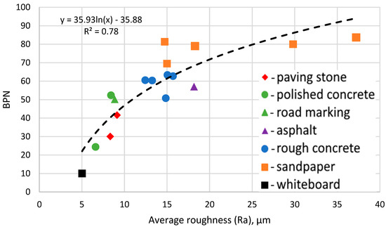
Figure 14.
The correlation between BPN value and average roughness.
During the roughness assessment, the standard deviation was calculated for the 20 replicate measurements of each surface type. The average standard deviation was 21.5% of the average result. A high standard deviation was obtained due to the limited horizontal range of the profilometer and high variations of the surface microtexture. However, a sufficient number of measurements can be taken to reduce any error during the assessment of any given surface, and this should be considered in future research.
A strong correlation between BPN and average roughness was found. This correlation did not depend on the type of material, and a difference in macrotexture did not affect it either. That validates the possibility of microtexture test application for the friction surveys. The Ra value, however, does not entirely describe the microtexture by ignoring the shape of asperities, which describes some difference between sandpaper and rough concrete on a graph. The difference, however, was not significant for practical measurements. The correlation obtained in this study (R2 = 0.78) was slightly lower than in other studies (Table 1). However, the surfaces were significantly more varied than for the other studies. That is, the data obtained in this study covers a broader range of surface roughness compared to all the studies detailed in Table 1, meaning a lower correlation between the profilometer results and the BPN was expected.
It can be seen that the optimal microtexture average roughness was generally in the range between 10 μm and 20 μm. Above 20 μm, microtexture does not significantly increase the BPN value, which reached a maximum value of 80 in the case of the sandpaper. Furthermore, values of microtexture below 10 μm resulted in a significant drop in the BPN value.
The obtained S-coefficient indicates that the wavelength threshold between microtexture and macrotexture, in terms of correlation between the British Pendulum Tester and the Ra value after macrotexture filtration, was approximately 0.3 mm. Those results correspond well to the PIARC classification, as shown in Figure 1 [2].
Taking into account the ready availability and economy of the proposed methodology, laser profilometry has the potential to be an effective tool for routine friction assessment when combined with a suitable macrotexture filtration algorithm. However, further testing on typical runway surfaces is required to assess the practical repeatability of the method and the influence of microtexture on the high-speed friction testing results obtained by continuous friction measurement equipment and other tools.
4. Conclusions
This study provides the required basis for the improvement in the friction measurement system by introducing microtexture measurements to runway surface friction assessment. This study focused on the design of a microtexture assessment algorithm that includes filtration and smothering techniques based on linear approximation and a laser profilometer. The laser profilometer model presented in this study was designed with economical and commonly available components and has a maximum vertical and horizontal resolution of 6 μm. The laser profilometer and microtexture assessment algorithm were validated and calibrated. This study revealed the following results:
- Laser profilometry testing equipment for the friction assessment can be economical and reliable.
- The optimal angle between the laser, camera, and surface was equal to 60°, which increases the vertical resolution of the profilometer without distorting the resulting profile.
- The proposed laser profilometry method results agreed with stylus-based roughness tester results, with a R2 coefficient of 0.99.
- A comparison of laser profilometer testing results to the British Pendulum Number of different pavement surfaces revealed that the average roughness had a good correlation with the British Pendulum Number (R2 = 0.78), which validates the friction assessment method based on texture testing.
- The filtration coefficient optimisation found that the wavelength threshold between microtexture and macrotexture, in terms of correlation between the British Pendulum Tester and average roughness, was approximately equal to 0.3 mm.
- Increasing microtexture roughness improves friction, but beyond 20 μm roughness has no significant effect on BPN value.
These findings show that cost-effective microtexture assessment can be used to assess friction. However, more research is needed to link texture measurements, including macrotexture measurements, to continuous friction measurement results. That research can be completed once the reliability and repeatability of the laser profilometer have been demonstrated on a range of real runway surfaces.
Author Contributions
Conceptualisation, G.W.; methodology, G.B.; software, G.B.; validation, G.B. and G.W.; formal analysis, G.B.; data curation, G.B.; writing—original draft preparation, G.B.; writing—review and editing, G.W.; visualisation, G.W.; supervision, G.W.; project administration, G.W.; funding acquisition, G.W. All authors have read and agreed to the published version of the manuscript.
Funding
This research was funded by the Airport Pavement Research Program.
Institutional Review Board Statement
Not applicable.
Informed Consent Statement
Not applicable.
Data Availability Statement
The products presented in this article are available on request from the corresponding author.
Conflicts of Interest
The authors declare no conflicts of interest.
Nomenclature
| h | µm | real height of the point on a profile |
| h′ | µm | height of the point on a registered profile |
| α | ° | angle between camera and surface |
| β | ° | angle between laser and surface |
| dn | µm | distance between point n and macro-profile |
| yn | µm | y-coordinate of the point n |
| xn | µm | x-coordinate of the point n |
| an | µm | y-intercept coefficient of an approximated line |
| bn | - | slope coefficient of an approximated line |
| S | points | filtration coefficient |
| xi | µm | x-coordinate of a point within the (n − S; n + S) or (n − S′; n + S′) range |
| yi | µm | y-coordinate of a point within the (n − S; n + S) or (n − S′; n + S′) range |
| a′n | µm | y-intercept coefficient of a line within the smothered profile |
| b′n | - | slope coefficient of a line within the smothered profile |
| y′n | µm | y-coordinate of a point n within the smothered profile |
| S′ | points | smothering coefficient |
| Ra | µm | average roughness of texture |
| BPN | - | British Pendulum Number |
| R2 | - | coefficient of determination |
References
- Sarsam, S. Field Assessment of Runway Pavement Surface Texture for Baghdad International Airport. Int. J. Transp. Eng. Traffic Syst. 2019, 5, 6–21. [Google Scholar]
- Chen, S.; Liu, X.; Luo, H.; Yu, J.; Chen, F.; Zhang, Y.; Ma, T.; Huang, X. A State-of-the-Art Review of Asphalt Pavement Surface Texture and Its Measurement Techniques. J. Road Eng. 2022, 2, 156–180. [Google Scholar] [CrossRef]
- White, G. Comparison of Bituminous Surface Options for Regional Airport Runway Pavements. In Bituminous Mixtures and Pavements VIII; CRC Press: London, UK, 2024; pp. 355–363. [Google Scholar]
- Giammaria Praticò, F.; Fedele, R. Road Pavement Macrotexture Estimation at the Design Stage. Constr. Build. Mater. 2023, 364, 129911. [Google Scholar] [CrossRef]
- White, G.; Almutairi, H. Laboratory and Field Performance Comparison of Dense Graded and Stone Mastic Asphalt as a Runway Surface. Int. J. Pavement Eng. 2022, 23, 937–949. [Google Scholar] [CrossRef]
- White, G.; Rodway, B. Distress and Maintenance of Grooved Runway Surfaces. In Proceedings of the Conference: Airfield Engineering and Maintenance Summit, Singapore, 25–28 March 2014. [Google Scholar]
- Pranjić, I.; Deluka Tibljaš, A.; Cuculić, M.; Skender, R. Pavement Surface Macrotexture Analysis. In Proceedings of the 5th International Conference on Road and Rail Infrastructure CETRA, Zadar, Croatia, 17–19 May 2018; pp. 359–365. [Google Scholar]
- Gayfutdinov, R.; Baimukhametov, G.; Hafizov, E. Pavement Wear Process and Abrasive Wear Resistance of Asphalt Concrete. E3S Web Conf. 2021, 274, 02008. [Google Scholar] [CrossRef]
- Gayfutdinov, R.F.; Bajmukhametov, G.F.; Gusmanova, T.F.; Hafizov, E.R. Wear Resistance Control System of Coarse Aggregate of Asphalt Concrete Mixtures and Assesment of Factors Affecting Abrasive Resistance of Crushed Stone. Roads Bridges 2020, 44, 231–253. [Google Scholar]
- Shakely, R.B.; Henry, J.J.; Heinsohn, R.J. Effects of Pavement Contaminants on Skid Resistance. In Proceedings of the 59th Annual Meeting of the Transportation Research Board, Washington, DC, USA, 21–25 January 1980; pp. 23–29. [Google Scholar]
- Xiao, S.; Xi, C.; Xu, L.; Li, J.; Tan, Y. Effects of Road Particulate Contaminants on Pavement Skid Resistance. Road Mater. Pavement Des. 2024, 25, 874–887. [Google Scholar] [CrossRef]
- Kane, M.; Edmondson, V. Modelling the Bitumen Scour Effect: Enhancement of a Dynamic Friction Model to Predict the Skid Resistance of Rubber upon Asphalt Pavement Surfaces Subjected to Wear by Traffic Polishing. Wear 2018, 400–401, 100–110. [Google Scholar] [CrossRef]
- Huan, X.; Sheng, Y.; Zhao, X.; Li, L.; Xue, H.; Ye, Z.; Xiong, R.; Wang, L. Skid-Resistance Durability and Wear/Polish-Resistance Behaviors of Ultra-Thin Friction Course Designed Based on the Differential Polishing of Aggregates. J. Build. Eng. 2023, 78, 107585. [Google Scholar] [CrossRef]
- Ganji, M.R.; Golroo, A.; Sheikhzadeh, H.; Ghelmani, A.; Arbabpour Bidgoli, M. Dense-Graded Asphalt Pavement Macrotexture Measurement Using Tire/Road Noise Monitoring. Autom. Constr. 2019, 106, 102887. [Google Scholar] [CrossRef]
- ICAO. Annex 14—Aerodromes—Volume I—Aerodromes Design and Operations; ICAO: Montreal, QC, Canada, 2022; pp. 1–352. [Google Scholar]
- ICAO. Procedures for Air Navigation Services—Aerodromes (Doc 9981); ICAO: Montreal, QC, Canada, 2020. [Google Scholar]
- Gallaway, B.M.; Tomita, H. Microtexture Measurements of Pavement Surfaces; Interim Report Research Report Number 138-1; Vehicle-Pavement Interaction Study; Texas A&M Transportation Institute: Bryan, TX, USA, 1970. [Google Scholar]
- McKeen, R.G.; Lenke, L.R.; Graul, R.A. Runway Rubber Removal Specification Development: Field Evaluation Procedures Development; New Mexico Engineering Research Institute: Albuquerque, NM, USA, 1984. [Google Scholar]
- van Es, G. How to Assess Runway Micro-Texture in Overruns on Wet Runways? In Proceedings of the ISASI 2021 Annual Seminar, Virtual Conference, 3 August–2 September 2021. [Google Scholar]
- Roy, N.; Kuna, K.K. Image Texture Analysis to Evaluate the Microtexture of Coarse Aggregates for Pavement Surface Courses. Int. J. Pavement Eng. 2023, 24, 2099854. [Google Scholar] [CrossRef]
- Xie, L.; Chu, X.; Wang, W.; Chen, C. A Stereoscopic Imaging Arithmetic for 3D Measurement of Road Surface Micro-Texture. In Proceedings of the International Conference on Transportation Engineering 2009, Chengdu, China, 25–27 July 2009; pp. 4228–4233. [Google Scholar]
- Gao, L.; Liu, M.; Wang, Z.; Xie, J.; Jia, S. Correction of Texture Depth of Porous Asphalt Pavement Based on CT Scanning Technique. Constr. Build. Mater. 2019, 200, 514–520. [Google Scholar] [CrossRef]
- Lin, Y.; Dong, C.; Wu, D.; Jiang, S.; Xiang, H.; Weng, Z. Study of Pavement Macro- and Micro-Texture Evolution Law during Compaction Using 3D Laser Scanning Technology. Appl. Sci. 2023, 13, 5736. [Google Scholar] [CrossRef]
- Gayfutdinov, R.F.; Khafizov, E.R. Research of Abrasive Wear of Crushed Stone for Highways. Izv. KGASU 2020, 51, 128–137. [Google Scholar]
- Martín-Béjar, S.; Cañero-Nieto, J.M.; Solano Martos, J.F.; Sevilla Hurtado, L. Laser Profilometry Application in Welding Geometrical Characterization. Key Eng. Mater. 2023, 960, 65–72. [Google Scholar] [CrossRef]
- Zelelew, H.; Khasawneh, M.; Abbas, A. Wavelet-Based Characterisation of Asphalt Pavement Surface Macro-Texture. Road Mater. Pavement Des. 2014, 15, 622–641. [Google Scholar] [CrossRef]
- Torbruegge, S.; Wies, B. Characterization of Pavement Texture by Means of Height Difference Correlation and Relation to Wet Skid Resistance. J. Traffic Transp. Eng. 2015, 2, 59–67. [Google Scholar] [CrossRef]
- Kokkalis, A.G.; Tsohos, G.H.; Panagouli, O.K. Consideration of Fractals Potential in Pavement Skid Resistance Evaluation. J. Transp. Eng. 2002, 128, 591–595. [Google Scholar] [CrossRef]
- Macek, W. Correlation between Fractal Dimension and Areal Surface Parameters for Fracture Analysis after Bending-Torsion Fatigue. Metals 2021, 11, 1790. [Google Scholar] [CrossRef]
- Kargah-Ostadi, N.; Howard, A. Monitoring Pavement Surface Macrotexture and Friction. Transp. Res. Rec. J. Transp. Res. Board 2015, 2525, 111–117. [Google Scholar] [CrossRef]
- Yang, G.; Li, Q.J.; Zhan, Y.; Fei, Y.; Zhang, A. Convolutional Neural Network–Based Friction Model Using Pavement Texture Data. J. Comput. Civ. Eng. 2018, 32, 04018052. [Google Scholar] [CrossRef]
- Li, Q.J.; Zhan, Y.; Yang, G.; Wang, K.C.P. Pavement Skid Resistance as a Function of Pavement Surface and Aggregate Texture Properties. Int. J. Pavement Eng. 2020, 21, 1159–1169. [Google Scholar] [CrossRef]
- Saito, K.; Henry, J.J. Development of the Relationships Between Skid Resistance and Pavement Surface Texture. Mem. Muroran Inst. Technol. 1987, 37, 293–307. [Google Scholar]
- Forster, S.W. Pavement Microtexture and Its Relation to Skid Resistance. Transp. Res. Rec. 1989, 1215, 151–164. [Google Scholar]
- Persson, B.N.J. Theory of Rubber Friction and Contact Mechanics. J. Chem. Phys. 2001, 115, 3840–3861. [Google Scholar] [CrossRef]
- Ueckermann, A.; Wang, D.; Oeser, M.; Steinauer, B. Calculation of Skid Resistance from Texture Measurements. J. Traffic Transp. Eng. 2015, 2, 3–16. [Google Scholar] [CrossRef]
- Ueckermann, A.; Wang, D.; Oeser, M.; Steinauer, B. A Contribution to Non-Contact Skid Resistance Measurement. Int. J. Pavement Eng. 2015, 16, 646–659. [Google Scholar] [CrossRef]
- Zuniga-Garcia, N.; Prozzi, J.A. High-Definition Field Texture Measurements for Predicting Pavement Friction. Transp. Res. Rec. J. Transp. Res. Board 2019, 2673, 246–260. [Google Scholar] [CrossRef]
- Deng, Q.; Zhan, Y.; Liu, C.; Qiu, Y.; Zhang, A. Multiscale Power Spectrum Analysis of 3D Surface Texture for Prediction of Asphalt Pavement Friction. Constr. Build. Mater. 2021, 293, 123506. [Google Scholar] [CrossRef]
- Chen, B.; Xiong, C.; Li, W.; He, J.; Zhang, X. Assessing Surface Texture Features of Asphalt Pavement Based on Three-Dimensional Laser Scanning Technology. Buildings 2021, 11, 623. [Google Scholar] [CrossRef]
- Kováč, M.; Brna, M.; Decký, M. Pavement Friction Prediction Using 3D Texture Parameters. Coatings 2021, 11, 1180. [Google Scholar] [CrossRef]
- Yang, G.; Wang, K.C.P.; Li, J.Q.; Wang, G. A Novel 0.1 Mm 3D Laser Imaging Technology for Pavement Safety Measurement. Sensors 2022, 22, 8038. [Google Scholar] [CrossRef] [PubMed]
- Zou, Y.; Yang, G.; Cao, M. Neural Network-Based Prediction of Sideway Force Coefficient for Asphalt Pavement Using High-Resolution 3D Texture Data. Int. J. Pavement Eng. 2022, 23, 3157–3166. [Google Scholar] [CrossRef]
- Apaza, F.R.A.; Jurado-Piña, R.; Díaz-Torrealba, R.; Gulisano, F.; Boada-Parra, G.; Gallego, J. Texture and Skid Resistance of Asphalt Mixtures with Crumb Rubber: Laboratory Assessment. Int. J. Pavement Eng. 2024, 25, 2378335. [Google Scholar] [CrossRef]
- Niu, Y.; Yu, X.; Zhu, H.; Zhou, W. Research on Estimation Method for Airport Runway Friction Coefficient Based on Numerical Analysis. IEEE Access 2024, 12, 37615–37630. [Google Scholar] [CrossRef]
- Paul, A.K.; Prasad, A.; Kumar, A. Review on Artificial Neural Network and Its Application in the Field of Engineering. J. Mech. Eng. Prakash 2022, 1, 53–61. [Google Scholar] [CrossRef]
- Chu, L.; Guo, W.; Fwa, T.F. Theoretical and Practical Engineering Significance of British Pendulum Test. Int. J. Pavement Eng. 2022, 23, 1–8. [Google Scholar] [CrossRef]
- Moore, D.F. Prediction of Skid-Resistance Gradient and Drainage Characteristics for Pavements. Highw. Res. Rec. 1966, 131, 181–203. [Google Scholar]
- Edjeou, W.; Cerezo, V.; Zahouani, H.; Salvatore, F. Multiscale Analyses of Pavement Texture during Polishing. Surf. Topogr. 2020, 8, 024008. [Google Scholar] [CrossRef]
- Florková, Z.; Pepucha, L. Microtexture Diagnostics of Asphalt Pavement Surfaces. IOP Conf. Ser. Mater. Sci. Eng. 2017, 236, 012025. [Google Scholar] [CrossRef]
- Ezhov, N.; Neitzel, F.; Petrovic, S. Spline Approximation, Part 1: Basic Methodology. J. Appl. Geod. 2018, 12, 139–155. [Google Scholar] [CrossRef]
- Harrell, F.E. Regression Modeling Strategies; Springer: Cham, Switzerland, 2015; ISBN 978-3-319-19424-0. [Google Scholar]
- Chen, X.-D.; Xu, G.; Yong, J.-H.; Wang, G.; Paul, J.-C. Computing the Minimum Distance between a Point and a Clamped B-Spline Surface. Graph Models 2009, 71, 107–112. [Google Scholar] [CrossRef]
- Chen, X.-D.; Su, H.; Yong, J.-H.; Paul, J.-C.; Sun, J.-G. A Counterexample on Point Inversion and Projection for NURBS Curve. Comput. Aided Geom. Des. 2007, 24, 302. [Google Scholar] [CrossRef][Green Version]
Disclaimer/Publisher’s Note: The statements, opinions and data contained in all publications are solely those of the individual author(s) and contributor(s) and not of MDPI and/or the editor(s). MDPI and/or the editor(s) disclaim responsibility for any injury to people or property resulting from any ideas, methods, instructions or products referred to in the content. |
© 2024 by the authors. Licensee MDPI, Basel, Switzerland. This article is an open access article distributed under the terms and conditions of the Creative Commons Attribution (CC BY) license (https://creativecommons.org/licenses/by/4.0/).