Communication

Few-Mode Fiber with Low Spontaneous Raman Scattering for Quantum Key Distribution and Classical Optical Communication Coexistence Systems

1
Institute of Basic Operations Technology, China Telecom Research Institute, Beijing 102209, China
2
China Academy of Information and Communications Technology, Beijing 102209, China
3
Key Laboratory of All Optical Network and Advanced Telecommunication Network of Ministry of Education, Beijing Jiaotong University, Beijing 100044, China
*
Author to whom correspondence should be addressed.
Sensors 2024, 24(23), 7645; https://doi.org/10.3390/s24237645
Submission received: 11 October 2024 / Revised: 22 November 2024 / Accepted: 28 November 2024 / Published: 29 November 2024
(This article belongs to the Special Issue Challenges and Future Trends in Optical Communications)

Abstract

:
In this paper, the theoretical model of spontaneous Raman scattering (SpRS) in few-mode fiber (FMF) is discussed. The influence of SpRS on quantum key distribution (QKD) in FMF is evaluated by combining wavelength division multiplexing (WDM) and space division multiplexing (SDM) techniques. On this basis, an improved ring-assisted FMF is designed and characterized; the transmission distance can be increased by up to 54.5% when choosing different multi-channels. The effects of forward and backward SpRS on QKD are also discussed.

1. Introduction

As a highly secure and reliable encryption method, QKD can generate secure keys between remote communication entities based on the inherent unpredictability of quantum physics [1]. It provides a theoretical basis for secure symmetric key encryption systems and has the potential to fundamentally alter the methods of protecting information exchange in the future. In the past few years, significant progress has been made in QKD research in terms of protocols and networks [2,3,4], including improvements to QKD protocols [5,6], noise analysis in quantum channels [7] and exploration of quantum relay networks [8,9]. The transmission distance and security key rate (SKR) of QKD have been greatly improved. In ultra-low-loss fiber, the transmission distance of QKD can reach up to 404 km [8], and the longest transmission distance of twin-field QKD is extended to 1002 km [10]. The highest SKR of high-speed QKD systems can reach 110 Mbps [11]. These advances have paved the way for the implementation of QKD networks. However, the high cost of deploying dedicated fibers is a major obstacle to the widespread use of QKD [12,13]. A promising solution to reduce deployment costs is to coexist QKD with classic optical communication. The coexistence system was first proposed in single-mode fiber (SMF) and has undergone a series of theoretical and experimental studies in WDM [14,15]. Nevertheless, the SpRS generated by classical signals is the biggest challenge of the scheme [16,17]. The wavelength range of Raman scattering exceeds 200 nm, making it susceptible to affecting quantum channels. It hinders the practical application of coexistence solutions in the most advanced technologies.
At the same time, in order to further improve the capacity, research on SDM has received increasing attention. Several types of optical fibers can achieve spatial multiplexing, such as multi-core fiber (MCF) [18], FMF, and few-mode multi-core fiber [19]. Among them, the modes supported by FMF can be used as parallel channels for independent signals. Compared with MCF, FMF has a simple manufacturing process and large effective mode field area, which is beneficial for reducing nonlinear noise and suitable for transmitting sensitive quantum signals [20,21]. Unfortunately, despite numerous experimental studies on FMF [22,23], there is limited theoretical research evaluating the impact of SpRS on QKD in FMF. Therefore, this paper explores the issue based on previous research. According to the conclusion, an improved ring-assisted FMF is designed, which significantly increases the signal transmission distance.

2. The SpRS When QKD Coexists with Classical Signals in FMF

In the coexistence system based on FMF, each mode only transmits classical or quantum signals, and the classical signals in each mode are at different wavelengths. This section will discuss the properties of the SpRS between modes in FMF and analyze its impact on the SKR of QKD systems.

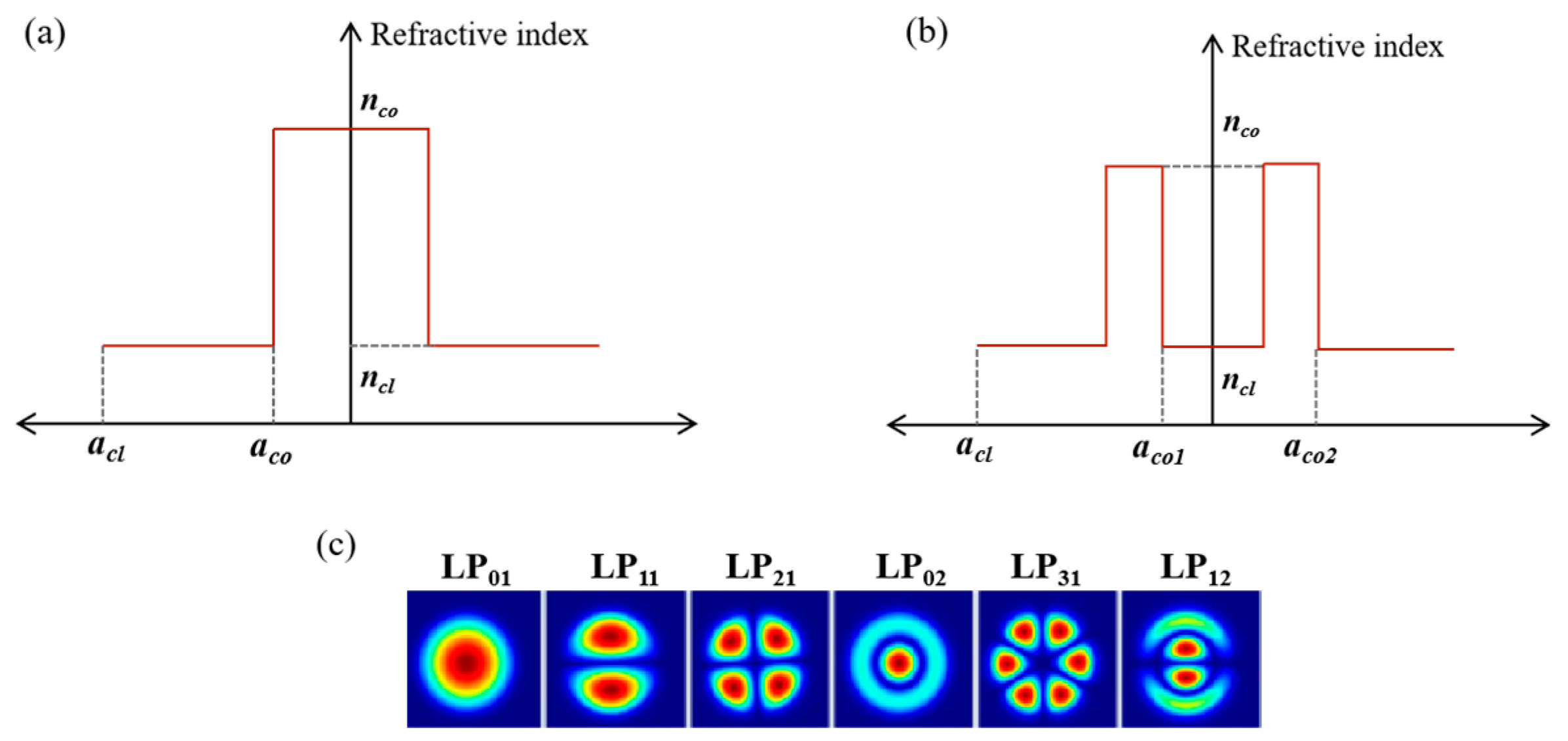
2.1. Derivation of the SpRS in FMF

The proposed SpRS is based on the inter mode crosstalk effect. Firstly, the process of mode crosstalk is derived as shown in Equations (l) and (2), where Pi and Pj are the transmitted powers in each channel along the z-axis, α is the attenuation coefficient in the channels, and hij is the power coupling coefficient [24].
d P j ( z ) d z = α z + h i j ( P j P i )
d P i ( z ) d z = α z + h i j ( P i P j )
Equations (3) and (4) can be obtained by solving Equations (1) and (2) for the conditions that Pj(0) = pc and Pi(0) = pq, which represent the initial power of the classical and quantum channel, respectively.
P j ( z ) = 1 2 ( p c + p q ) exp ( α z ) ( p c p q ) exp ( ( α + h i j ) z )
P i ( z ) = 1 2 ( p c + p q ) exp ( α z ) + ( p c p q ) exp ( ( α + h i j ) z )
Then, the derivation of SpRS is carried out, that is, the classical signal of the nth wavelength channel in jth mode generates SpRS in the mth quantum channel of ith mode. The SpRS is mainly composed of two parts. One is that the classical signals generate crosstalk in the channel of the quantum signal, which produces SpRS. The other part is that the classical signal generates SpRS in its own channel, and then the SpRS crosstalk in the channel of the quantum signal.
In the first part, assuming the transmission distance is dz, the power of forward SpRS is as follows [12]:
d P L I C X T F S R S ( z ) = η m n P I C X T ( z ) d z
where ηmn is the Raman scattering factor between the mth and nth wavelength channels, and PICXT(z) is the crosstalk power at dz, which can be obtained from Equation (4).
Due to channel loss, when the power of SpRS is transmitted to the output end of the fiber, the power can be obtained as shown in Equation (6). The equation can be integrated to obtain the power of the first part of the forward SpRS, as shown in Equation (7).
d P I C X T F S R S ( z ) = d P L I C X T F S R S ( z ) exp [ α q ( L z ) ]
P I C X T F S R S = 0 L d P I C X T F S R S ( z ) d z = 1 2 η m n e α i L p c + p q α i α j [ e ( α i α j ) L 1 ] p c p q α i α j 2 h i j [ e ( α i α j 2 h i j ) L 1 ]
A similar method is used to derive the second part of forward SpRS. The power of Raman scattering generated at the dz distance in jth mode is
d P L F S R S I C X T ( z ) = η m n P C S ( z ) d z
Pcs(z) is the power of the signal at dz, which can be obtained from Equation (3). The power crosstalks into the ith mode and transmits to the output port of the FMF, as shown in Equation (9).
d P F S R S I C X T ( z ) = d P L F S R S I C X T ( z ) exp [ α q ( L z ) ]
The power equation can be derived as [25,26]:
P F S R S I C X T = 0 L d P F S R S I C X T ( z ) d z = 1 2 η m n e α i L p c + p q α i α j [ e ( α i α j ) L 1 ] p c p q α i α j 2 h i j [ e ( α i α j 2 h i j ) L 1 ]
From the above derivation, it can be concluded that the forward SpRS is
P F S R S = P I C X T F S R S + P F S R S I C X T = η m n e α i L p c + p q α i α j [ e ( α i α j ) L 1 ] p c p q α i α j 2 h i j [ e ( α i α j 2 h i j ) L 1 ]
For the case of multiple classical channels, the forward SpRS of the mth channel in ith mode can be calculated as
P F _ S p R S = j = 1 J n = 1 N P F S R S j , n
Similarly, the backward SpRS can be obtained as
P B S R S = P I C X T B S R S + P B S R S I C X T = η m n p c p q α i + α j + 2 h i j [ 1 e ( α i + α j + 2 h i j ) L ] + p c + p q α i + α j [ 1 e ( α i + α j ) L ]
For the case of multiple classical channels, the backward SpRS of the mth channel in ith mode can be calculated as
P B _ S p R S = j = 1 J n = 1 N P B S R S j , n

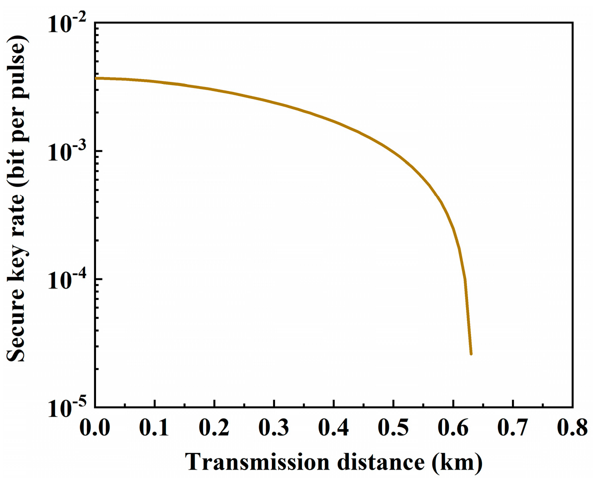
2.2. Impact of the SpRS on QKD

The protocol used in the simulation is the BB84 protocol with decoy-state method. The SKR is lower-bounded by [27]
R = q Q μ f e H 2 ( E μ ) + Q 1 [ 1 H 2 ( e 1 ) ]
where H2 is the binary Shannon entropy, q is set to 1/2 for the BB84 protocol, and fe accounts for the efficiency of error correction, which is set to 1.15. μ is the average number of photons in one pulse. Qμ and Eμ are the overall gain and the quantum bit error rate. Q1 and e1 are the gain and the error rate of a single-photon state. Qμ and Eμ can be obtained by Y0, which is the noise count including the dark count of the single photon detector and the SpRS noise. Considering the widely used dual-detector system, Y0 can be expressed as Ref. [12],
Y 0 = 2 p d a r k + p S R S
where pdark is the dark count rate of each single photon detector. pSRS is the noise photon caused by the SpRS, which can be calculated by [15].
p S R S = P F _ S p R S × Δ f × Δ t h × f ,   f o r w a r d P B _ S p R S × Δ f × Δ t h × f ,   b a c k w a r d
where h is the Planck’s constant, and f is the frequency of the quantum channel. Δf is the receiving bandwidth of the quantum channel, and Δt is the detector effective gating width.

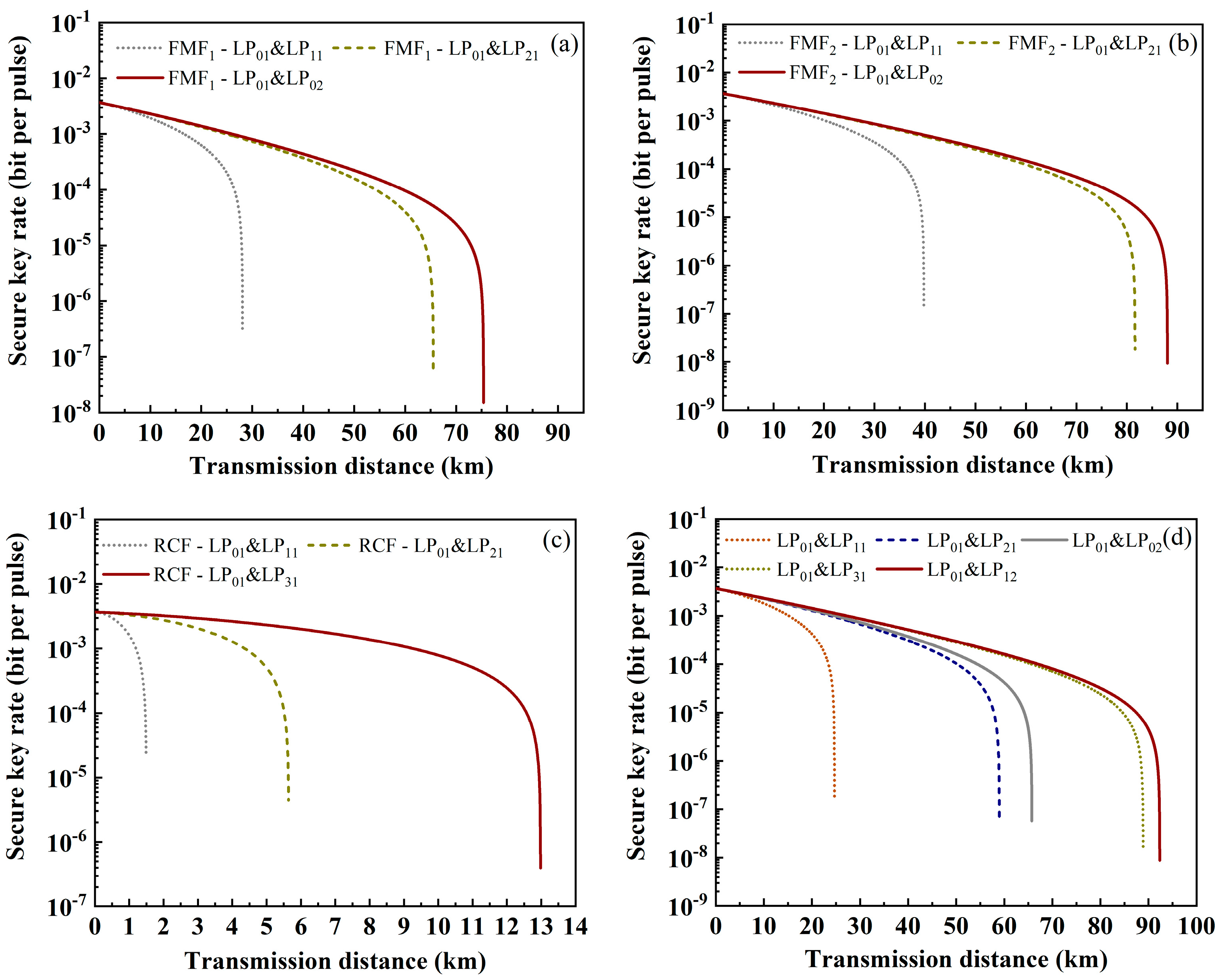
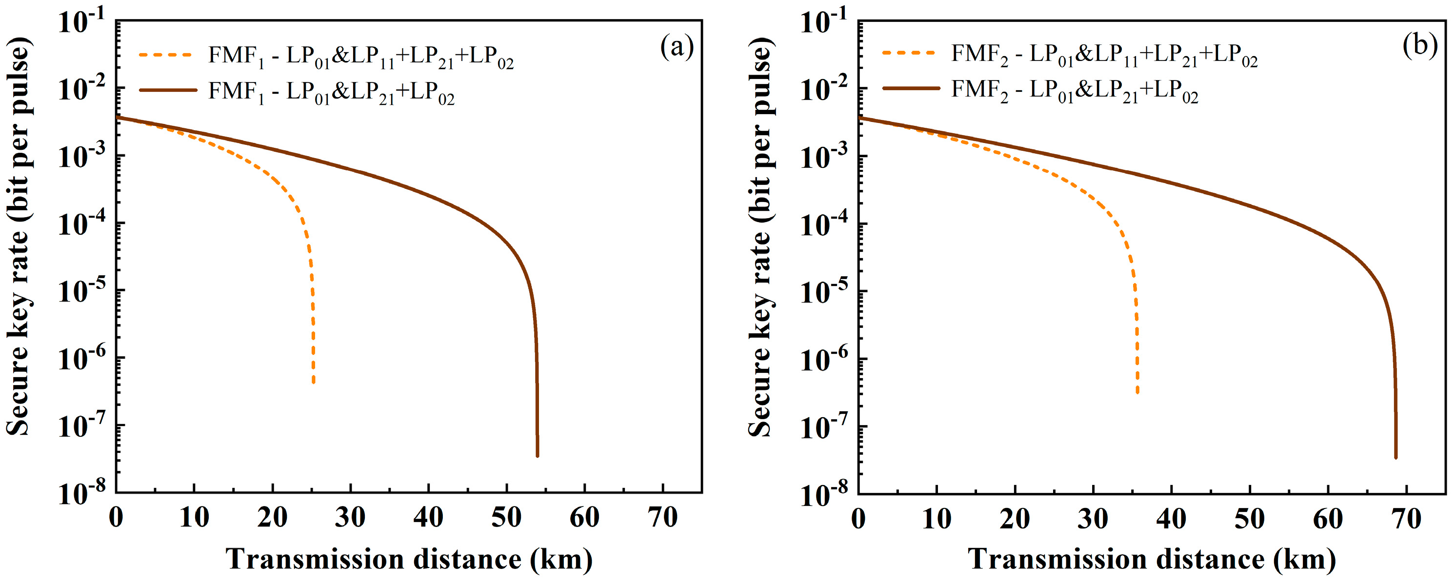
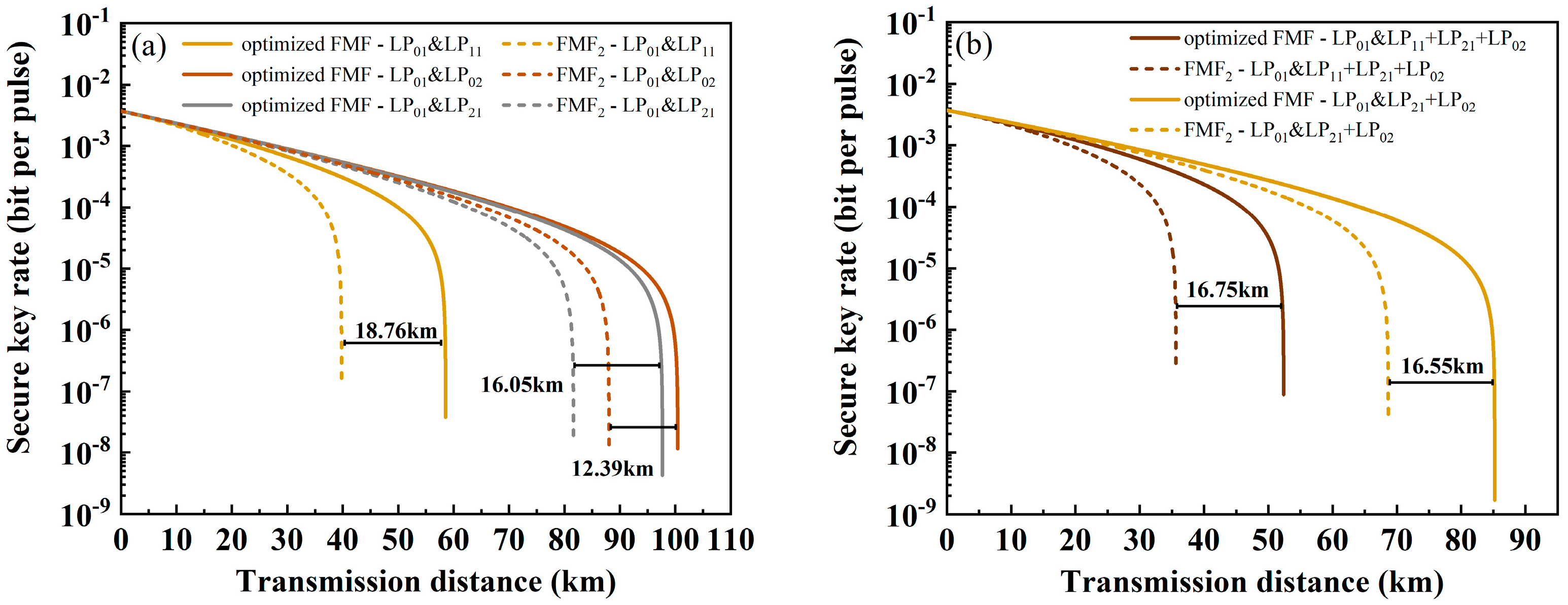
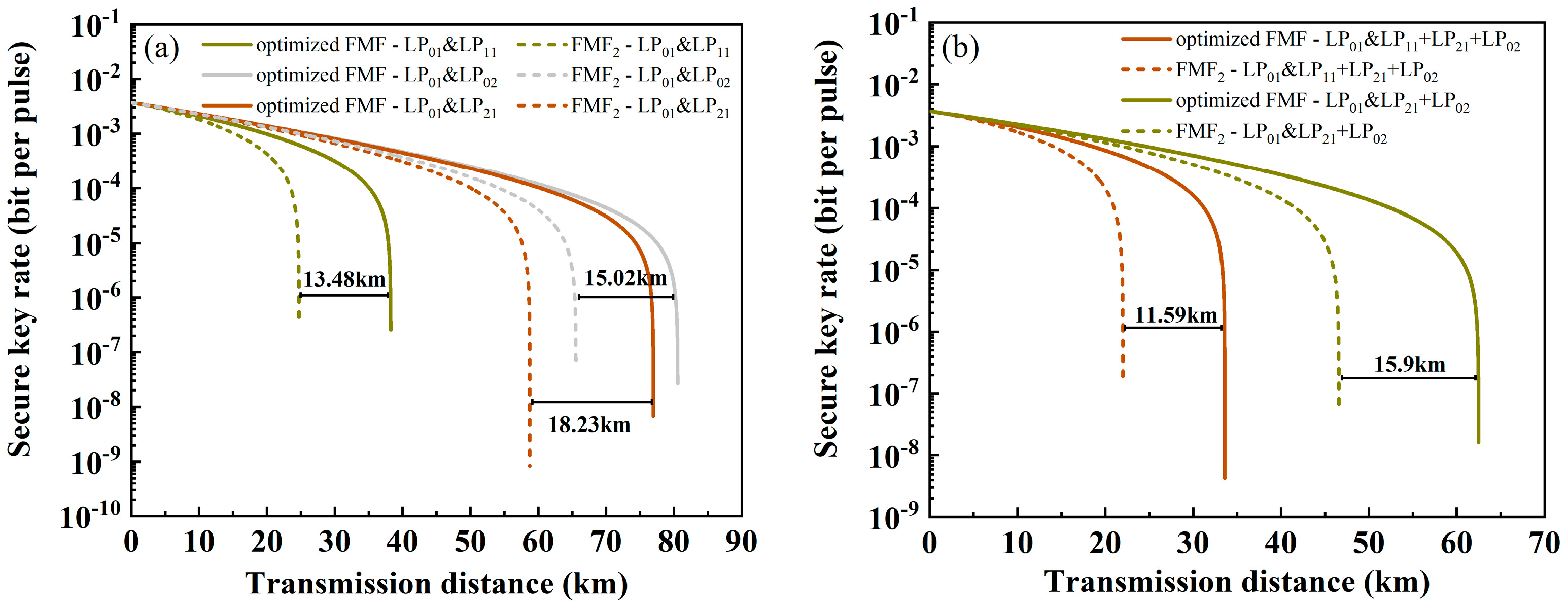
3. Performance of QKD in FMFs

On the basis of the above derivation, the performance of QKD at multiple wavelengths in SMF is demonstrated. In simulation, the quantum channel is at 1550.12 nm, corresponding to ITU standard channel. The classical channels are 1539.77~1542.14 nm with a wavelength interval of 0.8 nm. ηmn between the quantum channel and classical channels can be obtained from Ref. [15]. The commercial SMF used is a step-index fiber, with the structure shown in Figure 1a and parameters listed in Table 1. The power of classical signals is set to 0 dBm, and the power of the quantum signal is −80 dBm. According to Equation (15), the maximum transmission distance of the quantum signal is only 0.64 km due to the interference of SpRS, as shown in Figure 2. In order to increase the transmission distance, the coexistence system is applied in FMF.
As can be seen from Equations (11)–(14), the power of SpRS in FMF is related to the fiber length and the initial power of the signal, α and hij. Among them, the parameters determined by FMF itself are α and hij. The hij can be expressed as [28]
h i j = 2 d c κ i j 2 1 + [ d c ( β i β j ) ] 2
where β is the propagation constant. κij is the mode coupling coefficient, which can be calculated as [29]
κ i j = k 0 2 β j ( n 2 n 0 2 ) f i ( x , y ) f j ( x , y ) d x d y
where (n2n02) is the refractive index perturbation [30], and f(x,y) is the mode field distribution.
According to Equations (18) and (19), the hij of several commercial FMFs is calculated, and the characteristics applied to coexistence systems are analyzed. The fibers used include two kinds of four-mode fiber (FMF1 and FMF2), RCF and six-mode fiber (6MF). The structures of the fibers are shown in Figure 1a,b, and the parameters are listed in Table 1. The modes supported by each fiber are shown in Figure 1c. Furthermore, the refractive index difference (Δneff) and hij between modes are listed in Table 2 and Table 3, respectively. It is worth noting that, considering the practical application, the quantum channel is placed in LP01 mode and set to 1550.12 nm, so only the hij between LP01 and other modes is calculated in Table 3.
Figure 3 and Figure 4 show the relationship between SKR and transmission distance in a coexistence system based on FMF, where the quantum channel is LP01 and the classical channels are other modes. WDM technology is used in each classical channel, which can support four wavelengths at the same time. The wavelength range is still 1539.77~1542.14 nm with an interval of 0.8 nm. ηmn can be obtained from Ref. [15]. Referring to the parameters provided on the official website, α is set to 0.2 dB/km (LP01), 0.2 dB/km (LP11), 0.21 dB/km (LP21), 0.21 dB/km (LP02), 0.215 dB/km (LP31) and 0.215 dB/km (LP12). Figure 3 shows the variation in SKR in each fiber when the classic channel is only in one mode. Figure 4 is the variation in SKR when the classical signals have multiple modes. Comparing the two sets of figures, it can be seen that the quantum channel will suffer less interference and have a longer transmission distance when there are fewer modes of classical signals. In addition, it is found that when the classical signal is in LP11 mode, the transmission distance of the quantum signal will be greatly reduced, which is believed to be caused by the large mode coupling between LP01 and LP11.
According to previous research, mode coupling in FMFs is related to Δneff. As Δneff increases, Δβ also increases, resulting in a decrease in hij. Due to the fact that LP01 and LP11 are adjacent modes, the mode coupling is more pronounced. As reflected in Table 2 and Table 3, hij is at a low level when the Δneff is large. Therefore, in order to reduce the power of SpRS in coexistence systems and promote the performance of QKD, it is necessary to reduce hij, that is, increase the Δneff to a certain extent. Based on the above discussion, the optimization of FMF will be developed in the following section.

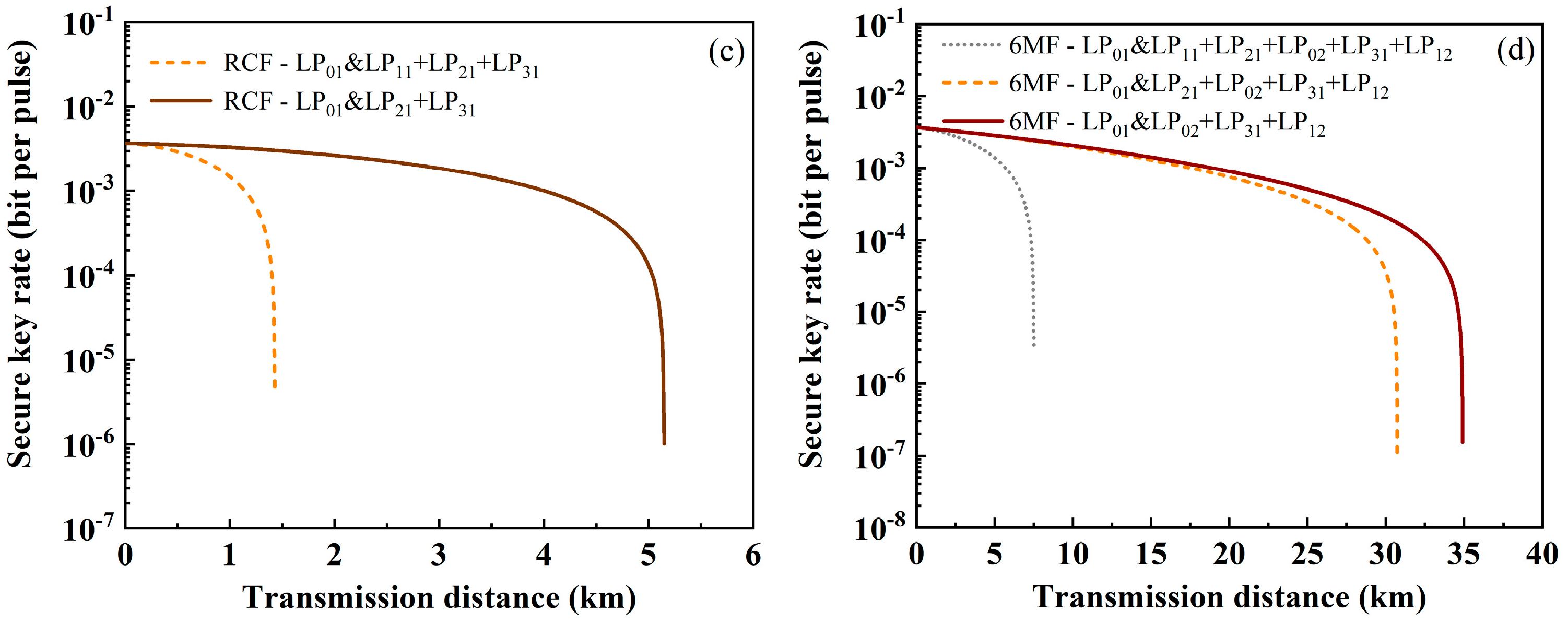
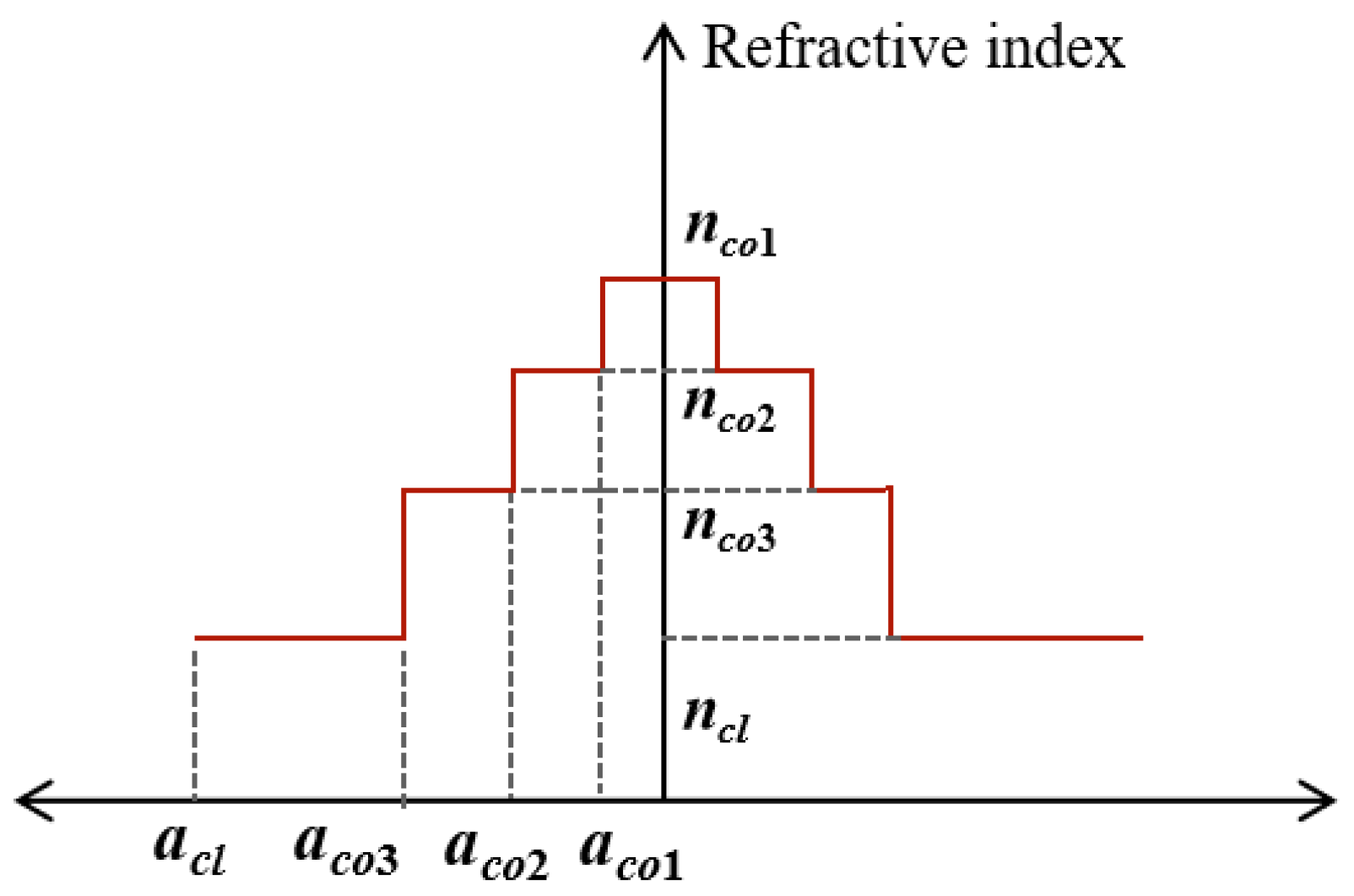
4. Performance of QKD in the Ring-Assisted FMF

The most intuitive way to improve Δneff is to increase the effective refractive index difference between core and cladding. However, for the given number of modes and parameters, a large Δneff means a small mode field area, making it difficult to suppress nonlinear effects. The trade-off between mode field area and Δneff in step-index fiber limits the overall performance [31]. In order to solve this contradiction, a ring-assisted FMF was designed [32,33]. The neff of modes is controlled by adding a refractive index ring in the fiber core. By carefully selecting parameters of the refractive index ring, the neff can be redistributed to optimize the effective refractive index difference between modes.
As shown in Figure 3 and Figure 4, the RCF has a large hij due to its structure characteristics, resulting in a short transmission distance. Six-mode fiber has difficulties in mode multiplexing and de-multiplexing in practical applications. In four-mode fiber, the transmission distance is longer, but there is also a large mode coupling between LP01 and LP11. Therefore, we used FMF2 as the basic parameter for design, where aco3 = 6 μm, acl = 62.5 μm, ncl = 1.444 and nco1 = 1.459. aco1 and aco2 are the radii of the refractive index rings, while nco2 and nco3 are the refractive indices of the two refractive index rings, as shown in Figure 5.
Considering the changes involving multiple parameters, the ergodic method was adopted for parameter design. Figure 6 shows the impact of variation in the refractive index ring radius and refractive index on Δneff. The radius ranges are 0.5~4.5 nm and 1.5~5 nm with an interval of 0.5 nm. The refractive index range is 1.445~1.454 with an interval of 0.001. According to the simulation results, the ring-assisted FMF parameters can be determined as aco2 = 5 μm, aco1 = 3.5 μm, nco2 = 1.457, and nco3 = 1.45. Correspondingly, the Δneff and hij of the ring-assisted FMF are listed in Table 4. Compared with the parameters in Table 2 and Table 3, the Δneff between LP01 and LP11 increases, while hij decreases significantly.
Then, the performance of QKD when using the ring-assisted FMF is calculated. Through WDM technology, each mode of the classical channel still contains four wavelengths. When the classic channel is only one mode, the variation between SKR and transmission distance is as shown in Figure 7a. The solid line represents the ring-assisted FMF, and the dotted line represents FMF2. It can be seen that the transmission distance has been greatly improved, with the classical channel showing the greatest improvement at LP11, reaching 58.54 km and showing an increase of 47.16%. When the classical channels are LP21 and LP02, the transmission distance of the quantum signal is increased by 23% and 10.9%, reaching 97.66 km and 100.42 km. Similarly, Figure 7b shows the variation in SKR with transmission distance when the classical channels have multiple modes. When it contains three modes (LP11, LP21, LP02) or two modes (LP21, LP02), the transmission distance increases by 47% (up to 52.39 km) and 24.1% (up to 85.21 km), respectively.
In Figure 8, the number of wavelengths in each mode of classical channels increases to ten, ranging from 1539.77 to 1546.92 nm with an interval of 0.8 nm. There is a significant variation in transmission distance at different numbers of wavelengths. Figure 8a shows the comparison of ring-assisted FMF and FMF2 performance in one mode. When the classic channels are LP11, LP21 and LP02, the transmission distance increases by 54.5%, 37.15% and 17.43%, reaching distances of 38.21 km, 76.97 km and 80.56 km, respectively. Furthermore, when the classical channels include three modes (LP11, LP21, LP02) or two modes (LP21, LP02), the performance comparisons are as shown in Figure 8b, where the transmission distances increase by 52.68% (up to 33.59 km) and 34.13% (up to 62.48 km).
The impact of forward and backward SpRS on SKR is also discussed in Figure 9 when using ring-assisted FMF. When there are four wavelengths in each mode, backward SpRS has more impairment of QKD, resulting in a shorter transmission distance. Increasing to ten wavelengths, forward SpRS causes greater damage. The number of wavelengths and channel modes can be selected according to actual applications.

5. Conclusions

In summary, this paper derives a simulation model of SpRS in FMF and discusses the impact of SpRS on QKD. The simulation results show that the influence of SpRS depends on the hij between modes. On this basis, a ring-assisted FMF is designed to effectively improve the transmission distance of signals in the coexistence system. Furthermore, the impact of forward and backward SpRS on SKR is also discussed. In practical applications, the number of wavelengths and channel modes can be selected according to the requirements.

Author Contributions

Conceptualization, Q.Z. and J.T.; methodology, Q.Z. and W.K.; software, Z.Z.; writing—original draft preparation, Q.Z. and J.Z.; writing—review and editing, Q.Z. and Z.Z.; validation, Q.Z. and W.K.; supervision, Y.L.; project administration, Y.L. All authors have read and agreed to the published version of the manuscript.

Funding

This research was supported by the Science and Technology Innovation 2030 Major Project (2021ZD0301300).

Institutional Review Board Statement

Not applicable.

Informed Consent Statement

Not applicable.

Data Availability Statement

The data presented in this study are available on request from the corresponding author.

Conflicts of Interest

The authors declare no conflicts of interest.

References

  1. Bennett, C.H.; Brassard, G. Quantum cryptography: Public key distribution and coin tossing. Theor. Comput. Sci. 2014, 560, 7–11. [Google Scholar] [CrossRef]
  2. Dynes, J.F.; Wonfor, A.; Tam, W.W.-S.; Sharpe, A.W.; Takahashi, R.; Lucamarini, M.; Plews, A.; Yuan, Z.L.; Dixon, A.R.; Cho, J.; et al. Cambridge quantum network. Npj Quantum Inf. 2019, 5, 101. [Google Scholar] [CrossRef]
  3. Liao, S.-K.; Cai, W.-Q.; Liu, W.-Y.; Zhang, L.; Li, Y.; Ren, J.-G.; Yin, J.; Shen, Q.; Cao, Y.; Li, Z.-P.; et al. Satellite-to-ground quantum key distribution. Nature 2017, 549, 43–47. [Google Scholar] [CrossRef]
  4. Fan-Yuan, G.-J.; Lu, F.-Y.; Wang, S.; Yin, Z.-Q.; He, D.-Y.; Chen, W.; Zhou, Z.; Wang, Z.-H.; Teng, J.; Guo, G.-C.; et al. Robust and adaptable quantum key distribution network without trusted nodes. Optica 2022, 9, 812–823. [Google Scholar] [CrossRef]
  5. Xu, F.; Xu, H.; Lo, H.-K. Protocol choice and parameter optimization in decoy-state measurement-device-independent quantum key distribution. Phys. Rev. A 2014, 89, 052333. [Google Scholar] [CrossRef]
  6. Shor, P.W.; Preskill, J. Simple Proof of Security of the BB84 Quantum Key Distribution Protocol. Phys. Rev. Lett. 2000, 85, 441–444. [Google Scholar] [CrossRef]
  7. Kong, W.; Sun, Y.; Gao, Y.; Ji, Y. Core and Wavelength Allocation Schemes for Noise Suppression in Quantum Key Distribution Over Multicore Fiber. IEEE J. Sel. Top. Quantum Electron. 2023, 29, 1–12. [Google Scholar] [CrossRef]
  8. Cao, Y.; Zhao, Y.; Li, J.; Lin, R.; Zhang, J.; Chen, J. Hybrid Trusted/Untrusted Relay-Based Quantum Key Distribution Over Optical Backbone Networks. IEEE J. Sel. Areas Commun. 2021, 39, 2701–2718. [Google Scholar] [CrossRef]
  9. Tang, J.-S.; Tang, L.; Xia, K. Three methods for the single-photon transport in a chiral cavity quantum electrodynamics system. Chin. Opt. Lett. 2022, 20, 062701. [Google Scholar] [CrossRef]
  10. Liu, Y.; Zhang, W.-J.; Jiang, C.; Chen, J.-P.; Zhang, C.; Pan, W.-X.; Ma, D.; Dong, H.; Xiong, J.-M.; Zhang, C.-J.; et al. Experimental Twin-Field Quantum Key Distribution over 1000 km Fiber Distance. Phys. Rev. Lett. 2023, 130, 210801. [Google Scholar] [CrossRef]
  11. Li, W.; Zhang, L.; Tan, H.; Lu, Y.; Liao, S.-K.; Huang, J.; Li, H.; Wang, Z.; Mao, H.-K.; Yan, B.; et al. High-rate quantum key distribution exceeding 110 Mb s–1. Nat. Photonics 2023, 17, 416–421. [Google Scholar] [CrossRef]
  12. Geng, J.-Q.; Fan-Yuan, G.-J.; Li, K.-J.; Tang, M.; Wang, S.; He, D.-Y.; Chen, W.; Yin, Z.-Q.; Guo, G.-C.; Han, Z.-F. Integration in the C-band between quantum key distribution and the classical channel of 25 dBm launch power over multicore fiber media. Opt. Lett. 2022, 47, 3111–3114. [Google Scholar] [CrossRef]
  13. Li, N.; Hu, C.; Lu, X.-M. Information-theoretic perspective on performance assessment and fundamental limit of quantum imaging. Chin. Opt. Lett. 2024, 22, 060009. [Google Scholar] [CrossRef]
  14. Qi, B.; Zhu, W.; Qian, L.; Lo, H.-K. Feasibility of quantum key distribution through a dense wavelength division multiplexing network. New J. Phys. 2010, 12, 103042. [Google Scholar] [CrossRef]
  15. Eraerds, P.; Walenta, N.; Legré, M.; Gisin, N.; Zbinden, H. Quantum key distribution and 1 Gbps data encryption over a single fibre. New J. Phys. 2010, 12, 063027. [Google Scholar] [CrossRef]
  16. Peters, N.A.; Toliver, P.; Chapuran, T.E.; Runser, R.J.; McNown, S.R.; Peterson, C.G.; Rosenberg, D.; Dallmann, N.; Hughes, R.J.; McCabe, K.P.; et al. Dense wavelength multiplexing of 1550 nm QKD with strong classical channels in reconfigurable networking environments. New J. Phys. 2009, 11, 045012. [Google Scholar] [CrossRef]
  17. Karinou, F.; Comandar, L.; Brunner, H.H.; Hillerkuss, D.; Fung, F.; Bettelli, S.; Mikroulis, S.; Wang, D.; Yi, Q.; Kuschnerov, M.; et al. Experimental Evaluation of the Impairments on a QKD System in a 20-Channel WDM Co-Existence Scheme. In Proceedings of the 2017 IEEE Photonics Society Summer Topical Meeting Series (SUM), San Juan, PR, USA, 10–12 July 2017; pp. 145–146. [Google Scholar]
  18. Dynes, J.F.; Kindness, S.J.; Tam, S.W.-B.; Plews, A.; Sharpe, A.W.; Lucamarini, M.; Fröhlich, B.; Yuan, Z.L.; Penty, R.V.; Shields, A.J. Quantum key distribution over multicore fiber. Opt. Express 2016, 24, 8081–8087. [Google Scholar] [CrossRef]
  19. Winzer, P.J. Making spatial multiplexing a reality. Nat. Photonics 2014, 8, 345–348. [Google Scholar] [CrossRef]
  20. Wang, B.-X.; Mao, Y.; Shen, L.; Zhang, L.; Lan, X.-B.; Ge, D.; Gao, Y.; Li, J.; Tang, Y.-L.; Tang, S.-B.; et al. Long-distance transmission of quantum key distribution coexisting with classical optical communication over a weakly-coupled few-mode fiber. Opt. Express 2020, 28, 12558–12565. [Google Scholar] [CrossRef]
  21. Stolen, R.H. Relation between the effective area of a single-mode fiber and the capture fraction of spontaneous Raman scattering. J. Opt. Soc. Am. B 2002, 19, 498–501. [Google Scholar] [CrossRef]
  22. Bacco, D.; Ding, Y.; Dalgaard, K.; Rottwitt, K.; Oxenløwe, L.K. Space division multiplexing chip-to-chip quantum key distribution. Sci. Rep. 2017, 7, 12459. [Google Scholar] [CrossRef] [PubMed]
  23. Cui, L.; Su, J.; Li, X.; Ou, Z.Y. Distribution of entangled photon pairs over few-mode fibers. Sci. Rep. 2017, 7, 14954. [Google Scholar] [CrossRef] [PubMed]
  24. Nakazawa, M.; Tokuda, M.; Negishi, Y. Measurement of polarization mode coupling along a polarization-maintaining optical fiber using a backscattering technique. Opt. Lett. 1983, 8, 546–548. [Google Scholar] [CrossRef] [PubMed]
  25. Sano, A.; Takara, H.; Kobayashi, T.; Miyamoto, Y. Crosstalk-Managed High Capacity Long Haul Multicore Fiber Transmission With Propagation-Direction Interleaving. J. Light. Technol. 2014, 32, 2771–2779. [Google Scholar] [CrossRef]
  26. Koshiba, M.; Saitoh, K.; Takenaga, K.; Matsuo, S. Analytical Expression of Average Power-Coupling Coefficients for Estimating Intercore Crosstalk in Multicore Fibers. IEEE Photonics J. 2012, 4, 1987–1995. [Google Scholar] [CrossRef]
  27. Lo, H.-K.; Ma, X.; Chen, K. Decoy State Quantum Key Distribution. Phys. Rev. Lett. 2005, 94, 230504. [Google Scholar] [CrossRef]
  28. Marcuse, D. Derivation of Coupled Power Equations. Bell Syst. Tech. J. 1972, 51, 229–237. [Google Scholar] [CrossRef]
  29. Li, G.; Bai, N.; Zhao, N.; Xia, C. Space-division multiplexing: The next frontier in optical communication. Adv. Opt. Photonics 2014, 6, 413–487. [Google Scholar] [CrossRef]
  30. Bures, J. Guided Optics: Optical Fibers and All-Fiber Components; John Wiley & Sons: Hoboken, NJ, USA, 2009. [Google Scholar]
  31. Sillard, P.; Bigot-Astruc, M.; Molin, D. Few-Mode Fibers for Mode-Division-Multiplexed Systems. J. Light. Technol. 2014, 32, 2824–2829. [Google Scholar] [CrossRef]
  32. Jiang, S.; Ma, L.; Zhang, Z.; Xu, Z.; Shuai, W.; Du, J.; Yang, C.; Tong, W.; He, Z. Design and characterization of ring-assisted few-mode fibers for weakly coupled mode-division multiplexing transmission. J. Light. Technol. 2018, 36, 5547–5555. [Google Scholar] [CrossRef]
  33. Lu, G.; Liu, S.; Lv, D.; Chen, M.; Zhang, Z. Design of ring-assisted few-mode fiber with low loss for improved mode-division multiplexing. Laser Phys. 2021, 31, 105101. [Google Scholar] [CrossRef]
Figure 1. The radius and refractive index distribution of (a) step-index fiber and (b) ring-core fiber (RCF). (c) The modes that can be supported in fibers.
Sensors 24 07645 g001
Figure 2. The relationship between secure key rate (SKR) and transmission distance in SMF.
Sensors 24 07645 g002
Figure 3. The relationship between SKR and transmission distance for classical signals in single mode. (a) FMF1, (b) FMF2, (c) RCF, and (d) 6MF.
Sensors 24 07645 g003
Figure 4. The relationship between SKR and transmission distance for classical signals in multiple modes. (a) FMF1, (b) FMF2, (c) RCF, and (d) 6MF.
Sensors 24 07645 g004aSensors 24 07645 g004b
Figure 5. The radius and refractive index distribution of the ring-assisted FMF.
Sensors 24 07645 g005
Figure 6. (a) The variation in Δneff with aco1 and aco2. (b) The variation in Δneff with nco2 and nco3.
Sensors 24 07645 g006
Figure 7. The relationship between SKR and transmission distance when using ring-assisted FMF (solid line) and FMF2 (dashed line) with four wavelengths in each mode. Among them, the classical channel is (a) one mode and (b) multiple modes.
Sensors 24 07645 g007
Figure 8. The relationship between SKR and transmission distance when using ring-assisted FMF (solid line) and FMF2 (dashed line) with ten wavelengths in each mode. Among them, the classical channel is (a) one mode; (b) multiple modes.
Sensors 24 07645 g008
Figure 9. The relationship between SKR and transmission distance when using ring-assisted FMF with (a) four wavelengths and (b) ten wavelengths in each mode.
Sensors 24 07645 g009
Table 1. The radius and refractive index of each fiber.
nconclacl (μm)aco (μm)
SMF1.4521.44462.53
FMF11.4521.44462.57
FMF21.4591.44462.56
RCF1.4591.44462.5aco1 = 4, aco2 = 7.5
6MF1.4561.44462.58
Table 2. The Δneff of the FMFs.
Δneff (×10−3)
LP01 and LP11LP11 and LP21LP21 and LP02LP31 and LP21LP02 and LP31LP31 and LP12
FMF12.42.90.6---
FMF23.54.51.2---
RCF0.72.1-3.1--
6MF2.12.80.9-2.41.6
Table 3. The hij of the FMFs.
hij (km−1)
LP01 and LP11LP01 and LP21LP01 and LP02LP01 and LP31LP01 and LP12
FMF13.72 × 10−45.40 × 10−53.55 × 10−5--
FMF21.7962 × 10−42.7054 × 10−52.0182 × 10−5--
RCF1.41 × 10−19.14 × 10⁻³-1.74 × 10⁻³-
6-MF4.8449 × 10−47.1666 × 10−55.3517 × 10−51.9382 × 10−51.6384 × 10−5
Table 4. The Δneff and hij of the ring-assisted FMF.
Δneff (×10−3)hij (km−1)
LP01 and LP11LP11 and LP02LP21 and LP02LP01 and LP11LP01 and LP02LP01 and LP21
ring-assisted FMF5.44.20.56.83 × 10−59.27 × 10−61.01 × 10−5
Disclaimer/Publisher’s Note: The statements, opinions and data contained in all publications are solely those of the individual author(s) and contributor(s) and not of MDPI and/or the editor(s). MDPI and/or the editor(s) disclaim responsibility for any injury to people or property resulting from any ideas, methods, instructions or products referred to in the content.

