Some studies emphasize indoor navigation for individuals with cognitive disabilities, particularly through mobile technology, to promote independence and improve quality of life. Our work distinguishes itself by offering a sensory navigation system that functions in both indoor and outdoor environments, providing route generation and detailed instructions. This comprehensive approach significantly enhances accessibility for individuals with cognitive disabilities in daily tasks and emergency situations. Our emphasis on sustainable technological solutions and inclusivity makes SmartRoutes a unique system designed to support the autonomy and well-being of individuals with cognitive challenges.
This paper presents several key contributions to the field of assistive technology for indoor navigation, particularly for individuals with cognitive disabilities:
3.1. SmartRoutes Architecture
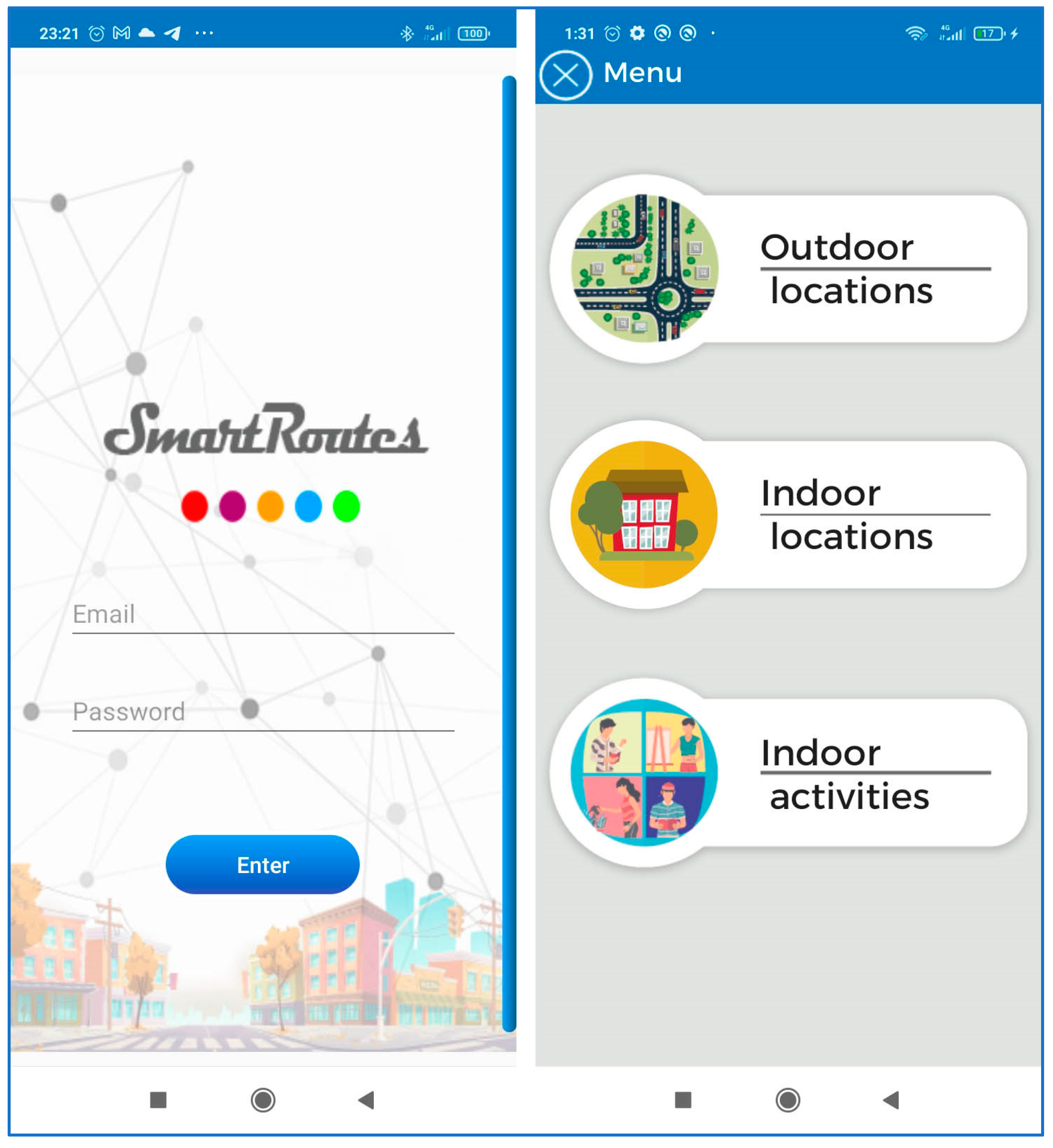
All the analyzed solutions share a common goal: to address current challenges in guiding and locating people in indoor environments, whether they have disabilities or not, and whether they are in emergency situations or everyday circumstances. Aligned with this objective, the SmartRoutes solution has been developed. SmartRoutes is an Android mobile application focused on the localization and positioning of users in indoor environments, with a focus on cognitive accessibility. The guidance applies to both everyday situations and emergency evacuations.
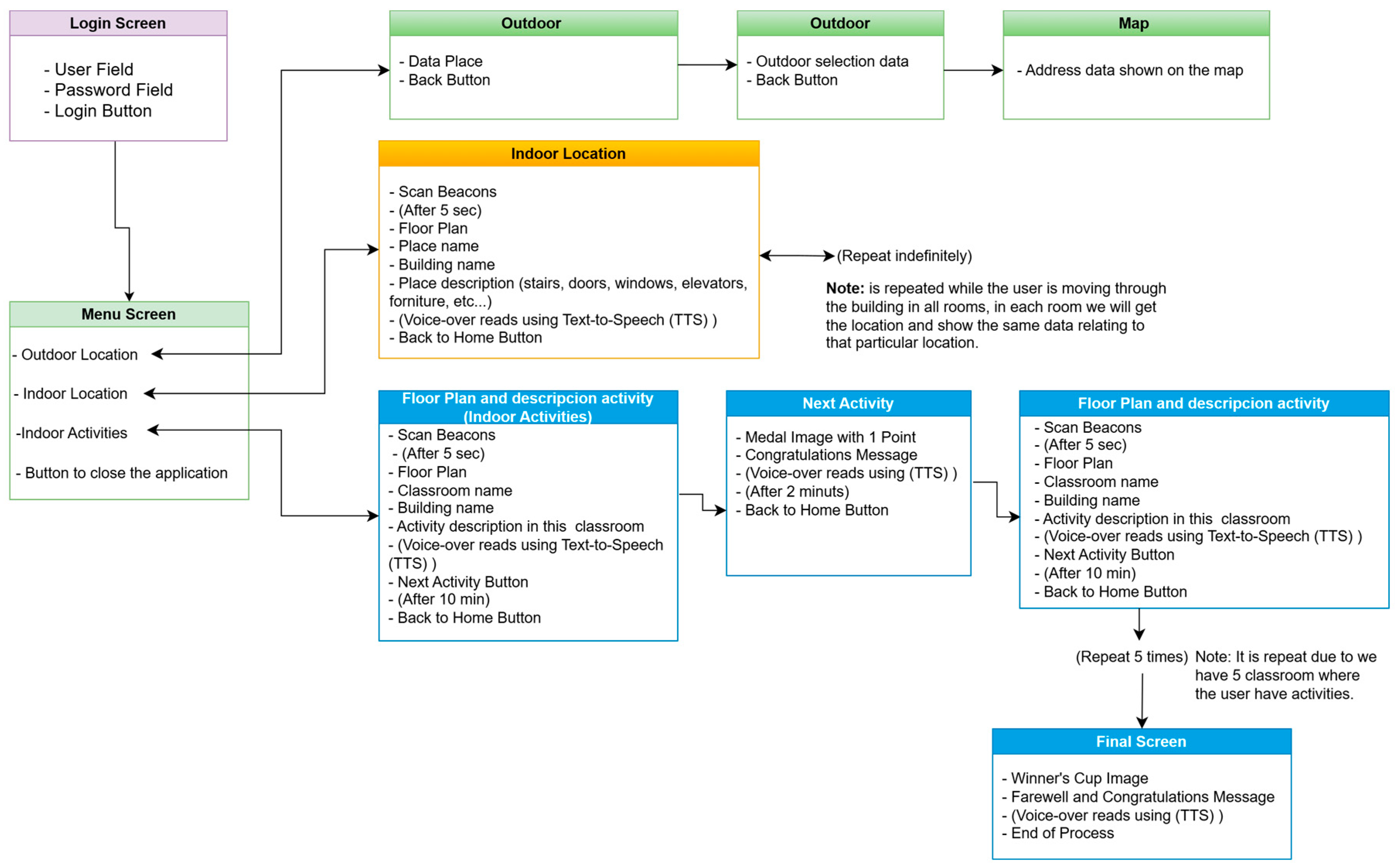
The application consists of three modules:
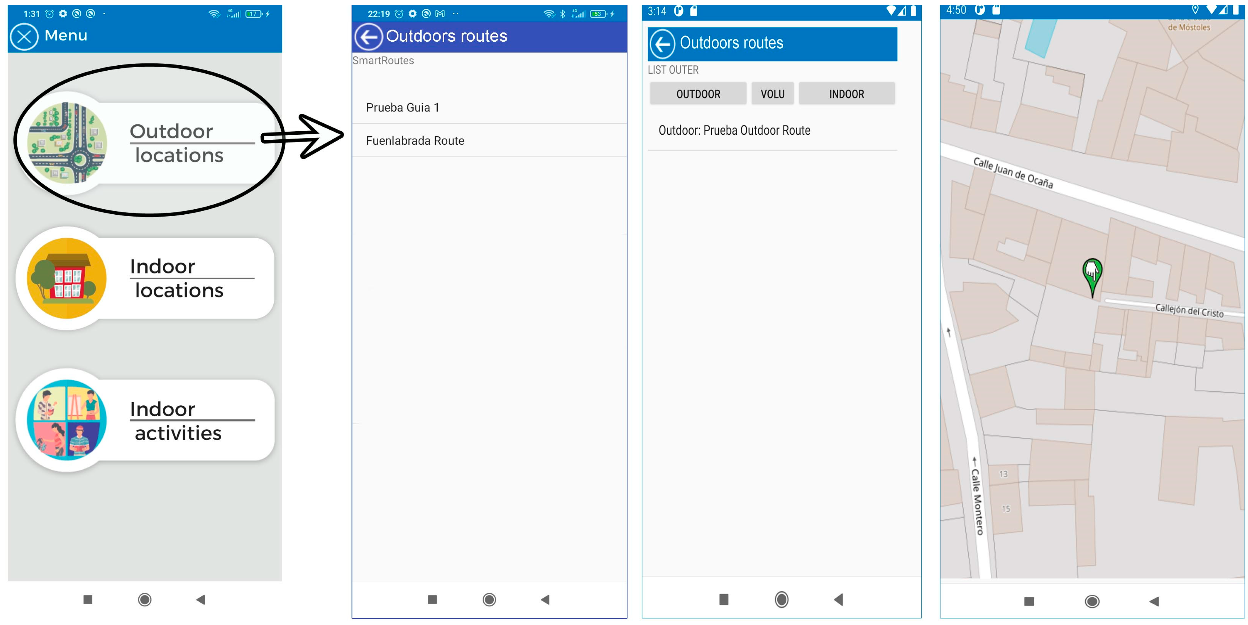
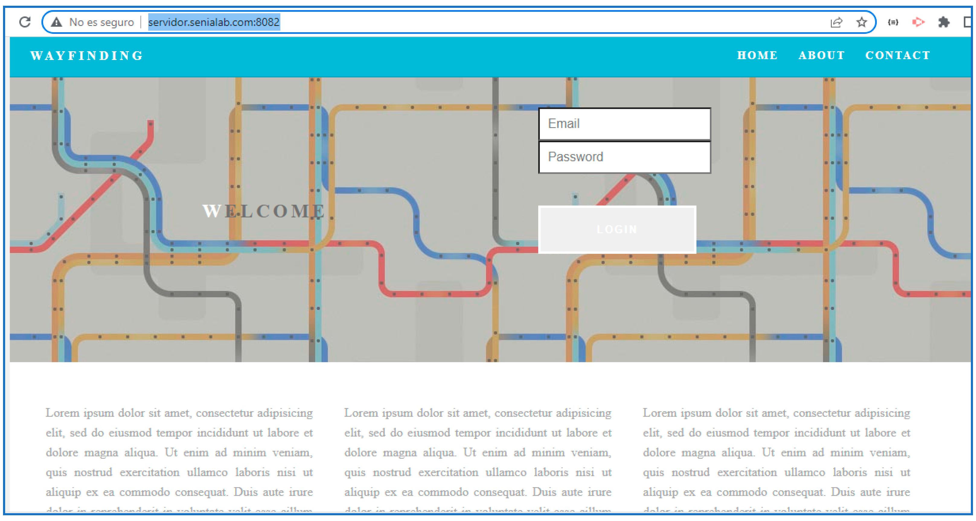
Outdoor location: This section uses maps based on OpenStreetMaps (OSM) connected to a “SmartRoutes Manager or SmartRM” (version 1.0) web platform, which communicates with the SmartRoutes mobile app via an external server. SmartRM is designed to allow users to generate outdoor routes. In SmartRM, a location is specified, such as a starting address (for example, the user’s home). This information is transferred to SmartRoutes and the app helps the user reach their destination, such as their workplace, using the OSM map.
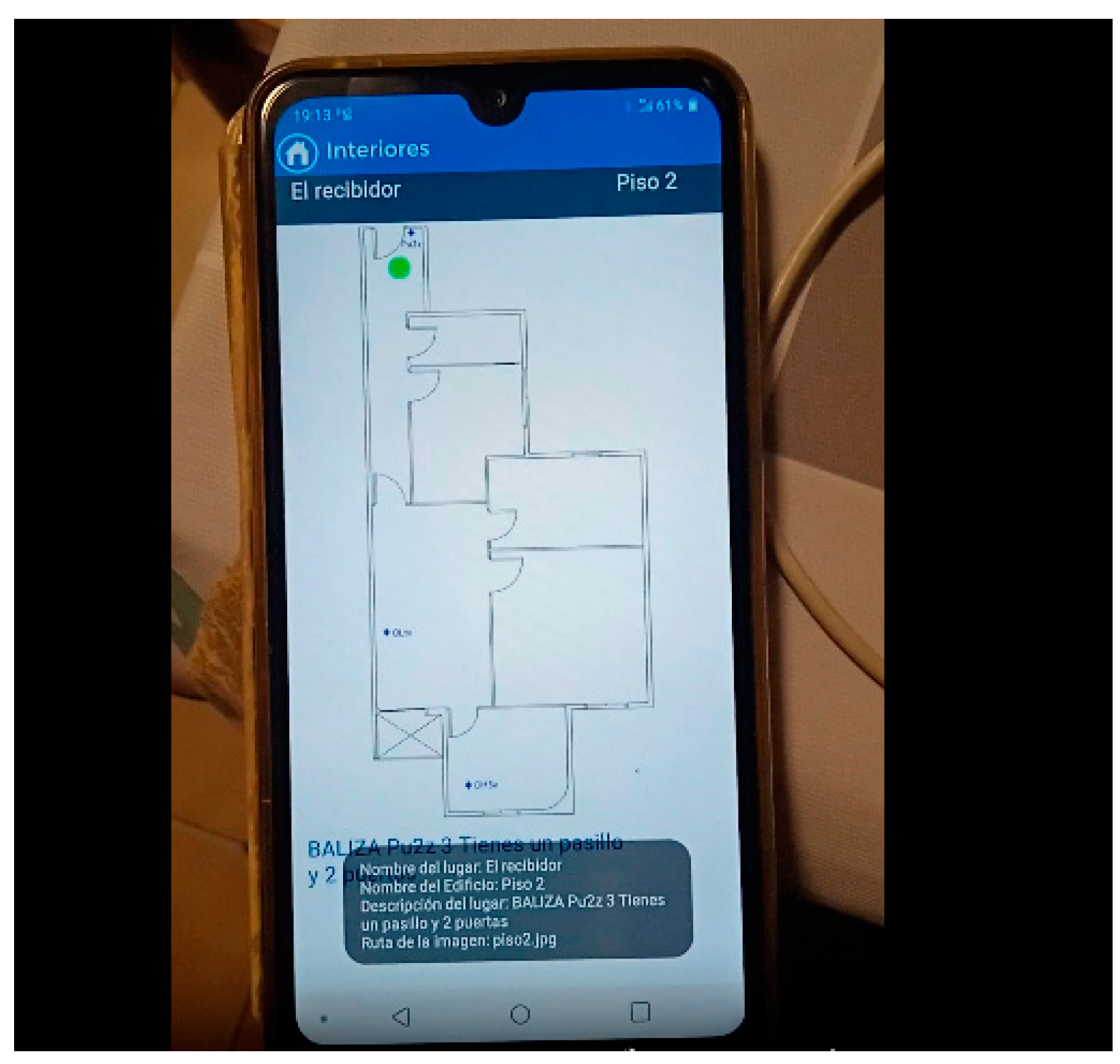
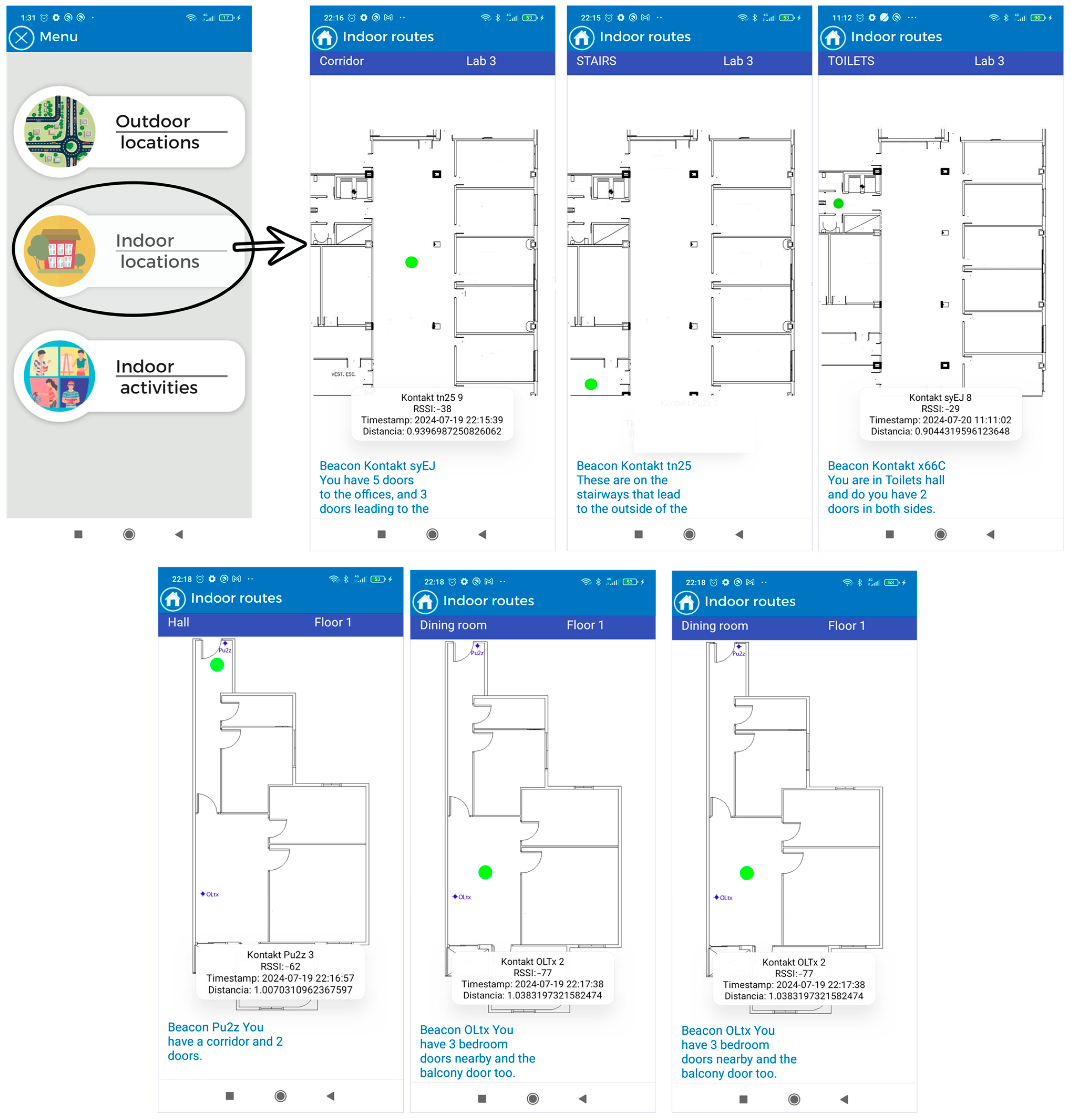
Indoor location with emergency guidance: In the event of indoor emergencies, the SmartRoutes mobile app provides audio directions and on-screen information about the user’s location. It also alerts users to potential obstacles in the environment. The entire process of data storage and connection is performed autonomously on the mobile device, without the need to connect to an external server database. This ensures that in hostile emergency situations where communication may be disrupted, the SmartRoutes app continues to function uninterruptedly. The SmartRM platform also allows for the generation of routes and points for indoor locations.
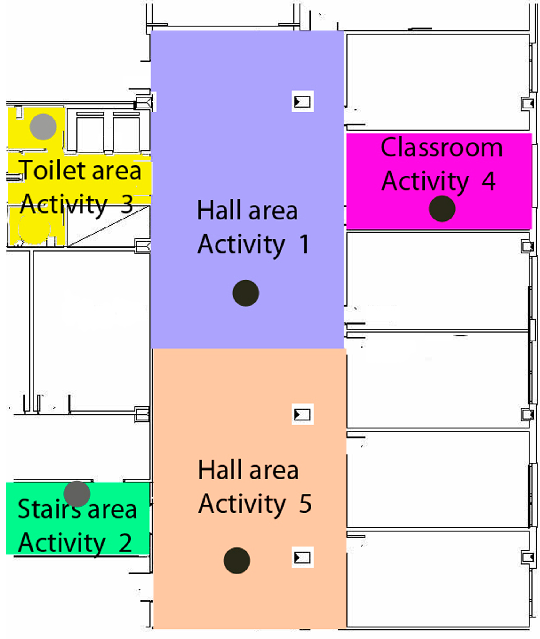
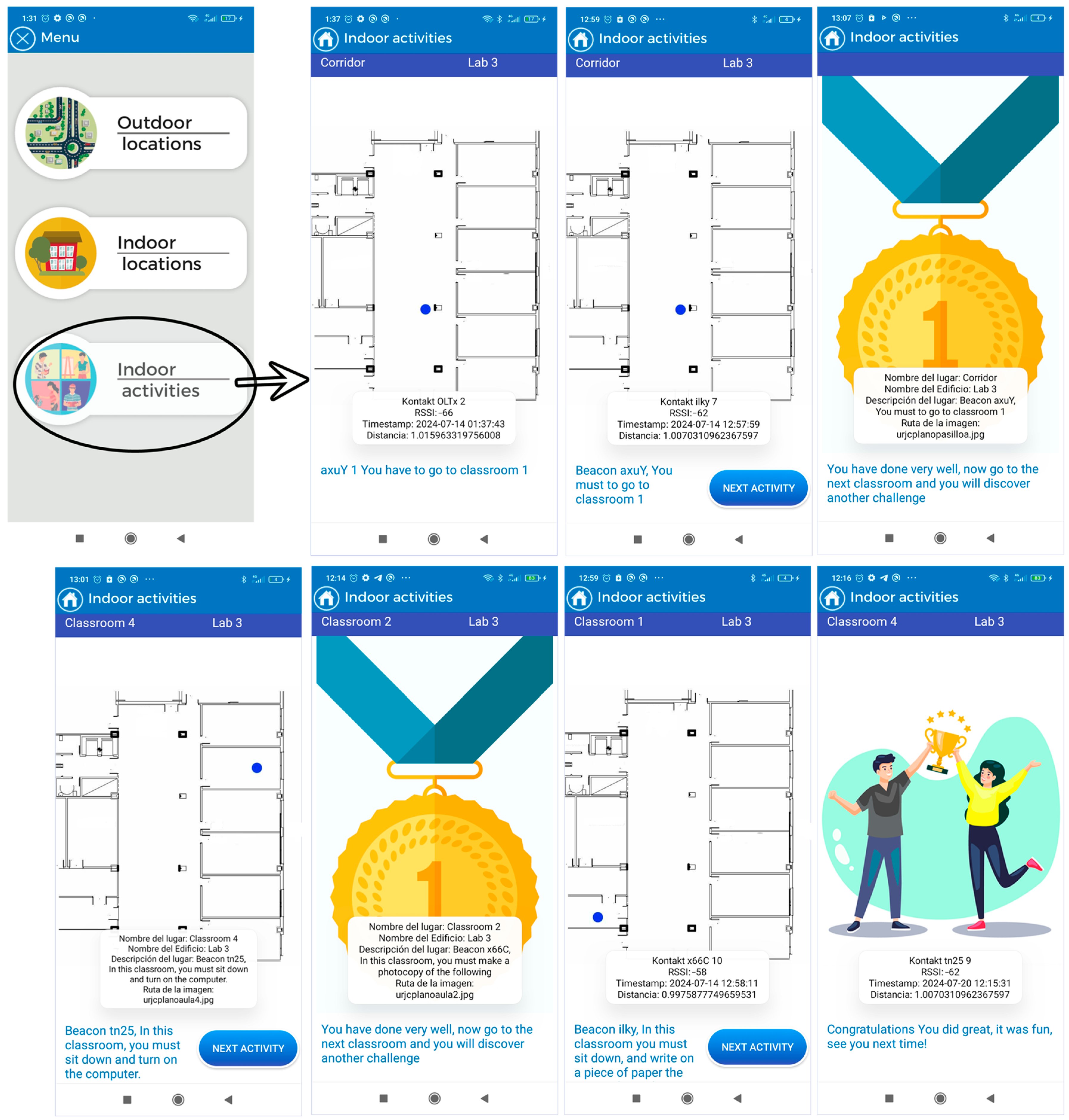
Indoor activities: This section allows users to engage in cognitive activities to improve concentration. Users move through classrooms within a building, and the app informs them of their current location and the activity they should perform. Each activity has a time limit of 10 min. Once the time is up, all activities conclude and the user receives feedback based on the activity performed. In this case, communication and data storage are also managed within the mobile device through an embedded database.
It is important to highlight that the module designed for activities involving gamification was developed to explore in greater depth how individuals with Down syndrome respond to tasks presented by a technological device. It examines how they manage and respond to long and abstract instructions compared to concise instructions that require a primary survival reaction. For example, in the emergency module, instructions are often brief and descriptive, as the messages describe elements that users visually perceive in their current environment. The type of response required from the user in these scenarios is more instinctive and primarily involve receiving an input and needing to perform an action (action–reaction effect). However, in the activities module, the user must listen, understand, and analyze, formulating a strategy within a short period to carry out the proposed activities. In this case, the reaction is not as immediate; the user can take some time to mentally analyze what needs to be done. Additionally, each activity assesses the user’s level of concentration on the task and their comprehension of the messages informing them of the tasks to be completed.
In this regard, we refer to the article by Özbeşer et al. [
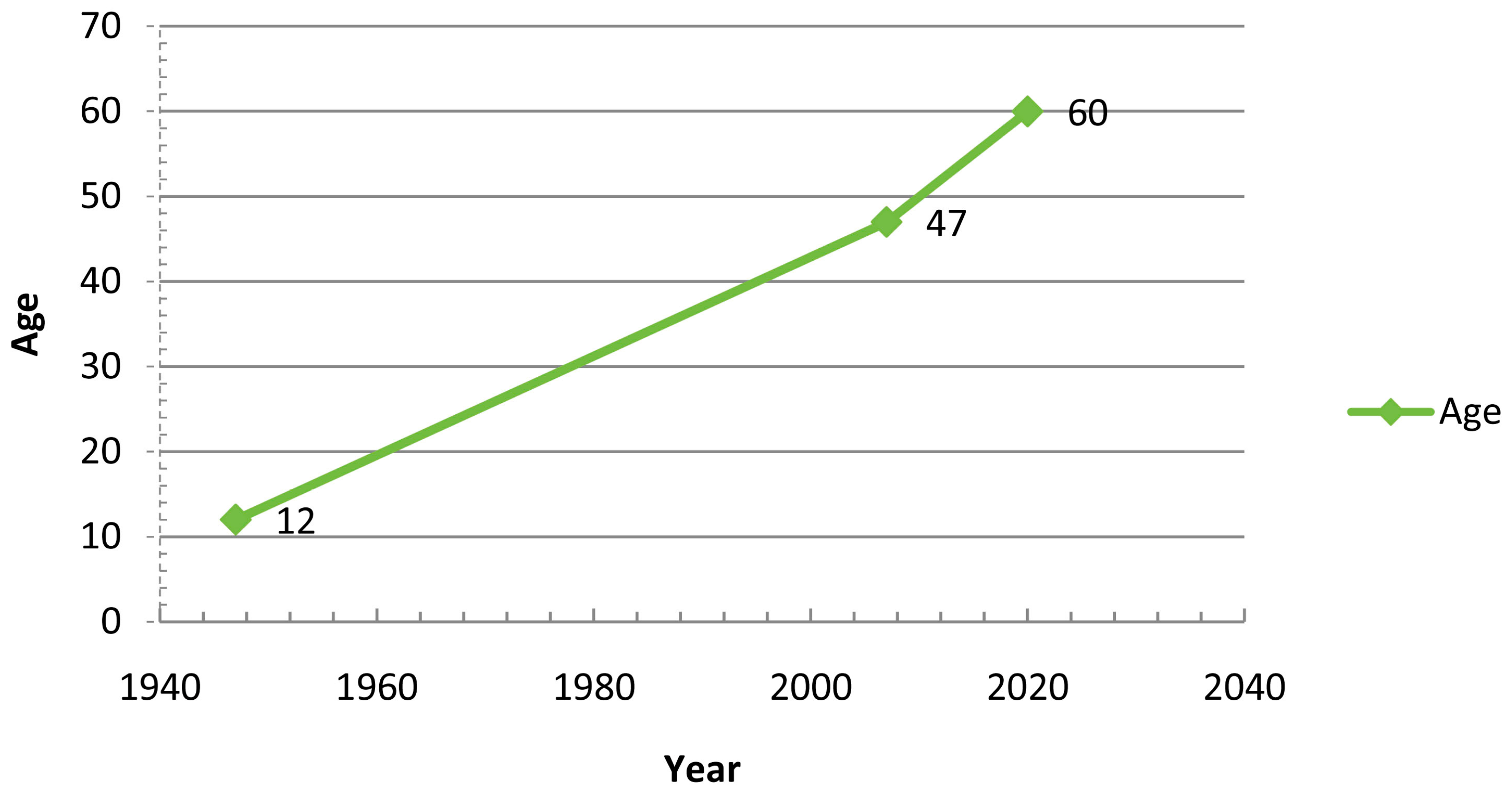
26], where the authors analyze the effectiveness of two approaches: Cognitive Orientation to Daily Occupational Performance (CO-OP) and Conductive Education (CE) on the motor skills of a group of 12 children with Down syndrome. To do so, they engaged the children in activities related to school/productivity, self-care, and play/leisure, examining which of the two approaches yielded better performance when the children were given specific tasks requiring concentration.
In recent developments in indoor navigation systems, there is a growing interest in creating solutions that cater to the specific needs of individuals with cognitive disabilities. These advancements aim to enhance accessibility and independence for this demographic in various indoor environments. By leveraging technologies such as Bluetooth Low Energy (BLE) and mobile devices, researchers are exploring innovative approaches to provide personalized guidance and support for individuals with cognitive disabilities in both routine and emergency situations. Additionally, the integration of user-friendly interfaces and inclusive design principles is becoming increasingly important to ensure the usability and effectiveness of these indoor navigation systems.
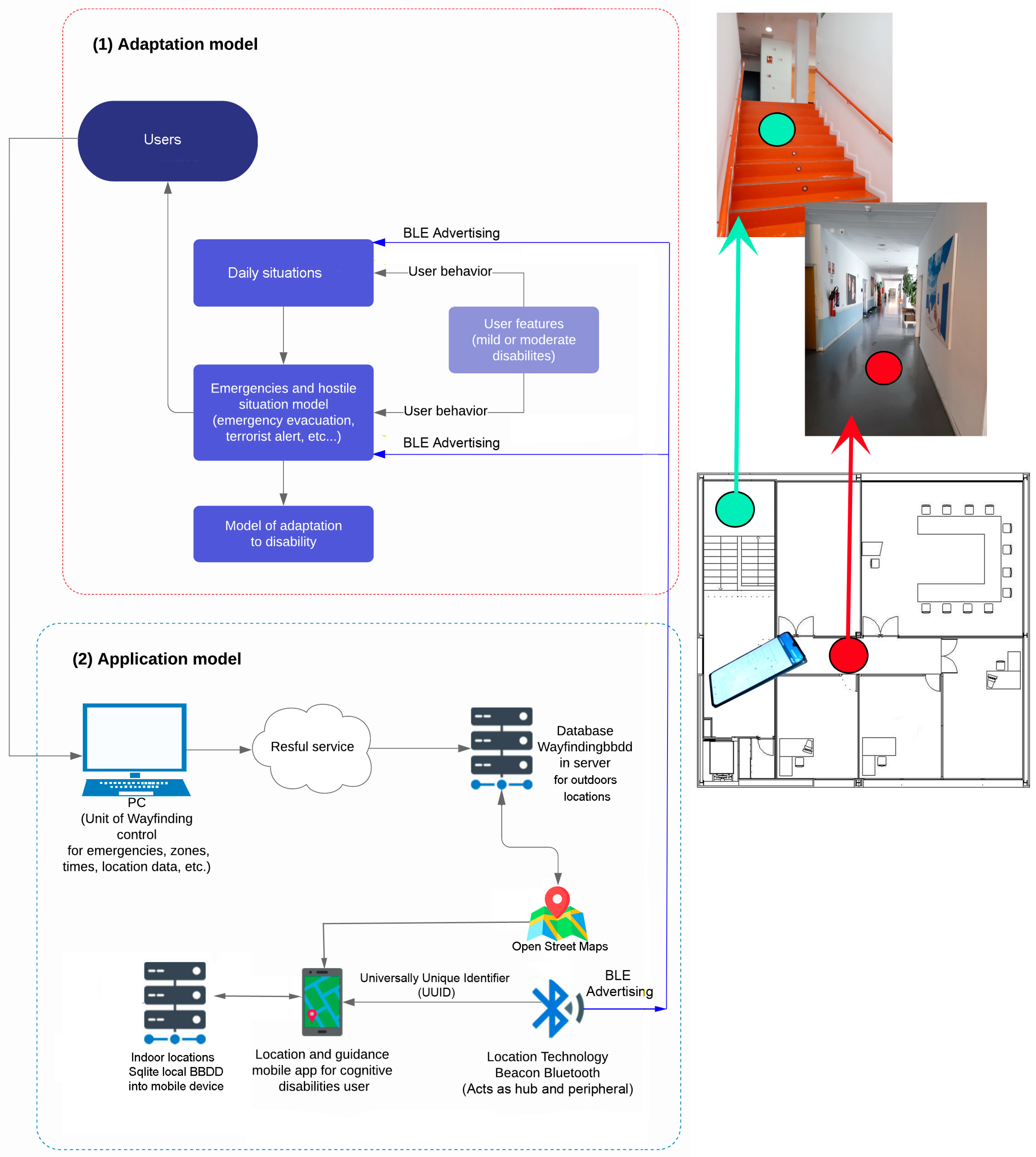
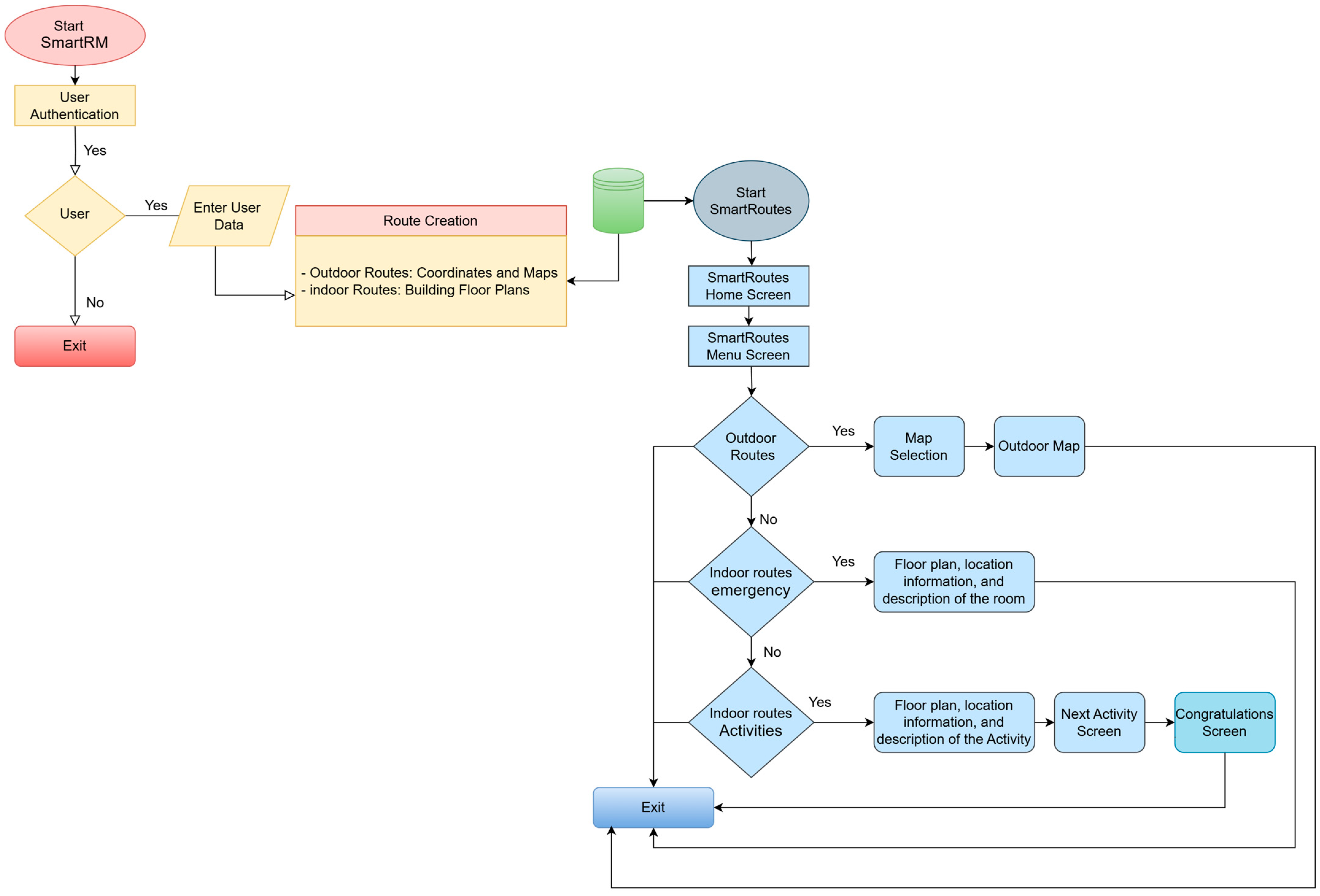
Figure 3 defines the final architecture of the guidance and localization solution based on Bluetooth Low Energy (BLE) technology. It represents the adaptation of users with mild to moderate cognitive disabilities to the solution and its usage environment under various environmental conditions, both in everyday situations and stressful circumstances involving hostile or emergency conditions.
In this model, two primary components are delineated. The outdoor component of the system is configured with high capacity, capable of accommodating up to 250 concurrent users while hosting both the database and web application. This configuration also supports the indoor environment, where users are not required to connect to a server for guidance due to the presence of a local SQLite database embedded within their devices. This feature ensures that the application remains autonomous and fully operational in emergency situations where communication disruptions may occur. The bidirectional location data obtained from Bluetooth beacons, which are essential for localization and guidance, are stored locally and synchronized with the server whenever feasible. For outdoor environments, a web platform is provided where users can input location requests, subsequently displayed on an OpenStreetMap interface via mobile devices. This configuration relies on the web server to efficiently manage and process location requests, ensuring accurate and timely display on the map interface.
The security and orientation information broadcast by the beacons, combined with user device position tracking data during movement, are stored in the server’s local database via the mobile device. This ensures that critical information required for both indoor guidance and outdoor localization is securely managed and accessible even during adverse conditions.
To adapt instructions to the specific needs of individuals with cognitive disabilities, the application focuses on providing simple and clear messages through both text and voice. These instructions are presented in short sentences and simple language, with an emphasis on intonation to aid memorization and the creation of mental maps. In hostile or emergency environments, where visual communication may be limited, audio messages are prioritized and complemented, when possible, by simple visual elements like graphics and images, in addition to text. This strategy of using simplified vocalizations and concise textual content seeks to ensure that instructions are both comprehensible and effective for individuals with cognitive disabilities, thereby enhancing their capacity for autonomous and safe navigation across diverse environments.
This study has addressed the urgent need to develop technological solutions that facilitate navigation and the management of daily activities for individuals with cognitive disabilities, particularly those with Down syndrome. Through the implementation of the SmartRoutes application, it has been demonstrated that it is possible to create personalized routes and platforms that not only optimize the execution of daily tasks but also promote effective learning in workplace environments.
In the context of the state of the art, there is a significant lack of accessible tools that integrate technology into the daily lives of individuals with disabilities. While there are applications and devices that address localization and guidance in indoor environments, few have been specifically designed to meet the needs of users with cognitive disabilities. This work stands out for its focus on accessibility and usability, employing a user-centered design that considers the capabilities and limitations of this population. The methodology adopted, which includes user testing in real environments, has validated the effectiveness of the application in both everyday and emergency situations, ensuring that the proposed solutions are practical and effective.
The differentiating elements of SmartRoutes include its ability to customize routes according to the individual needs of users, as well as its integration of Bluetooth BLE technology for precise localization. This technology not only enhances the user experience by providing real-time information but also allows users to interact with their environment more autonomously. Furthermore, the application has been designed to be intuitive, using clear language and voice messages that facilitate understanding, which is crucial for users with cognitive diversity.
Importantly, the results obtained from the testing phase, including detailed calculations of beacon localization accuracy and optimal scanning times, reinforce the effectiveness of the SmartRoutes system. These results demonstrate that the application can reliably locate users and provide timely guidance, which is essential for enhancing user confidence and independence in navigating both familiar and unfamiliar environments. The successful deployment of the system in various settings, as evidenced by the positive feedback from participants, further underscores its potential as a valuable tool for individuals with cognitive disabilities.
The implementation of SmartRoutes represents a powerful tool for managing routine activities, contributing to the autonomy of individuals with disabilities. By facilitating the execution of daily tasks and learning in workplace settings, this solution not only improves the quality of life for users but also promotes their social and labor integration. By providing an accessible means to navigate complex spaces, anxiety and stress associated with unfamiliar situations are reduced, thereby encouraging greater community participation.
In conclusion, this work not only offers an innovative solution to a persistent problem but also lays the groundwork for future research in the field of assistive technology. Future studies are suggested to focus on evaluating the application in a variety of contexts and with different user groups, as well as exploring new technologies that could further complement and enhance the navigation and activity management experience for individuals with cognitive disabilities.
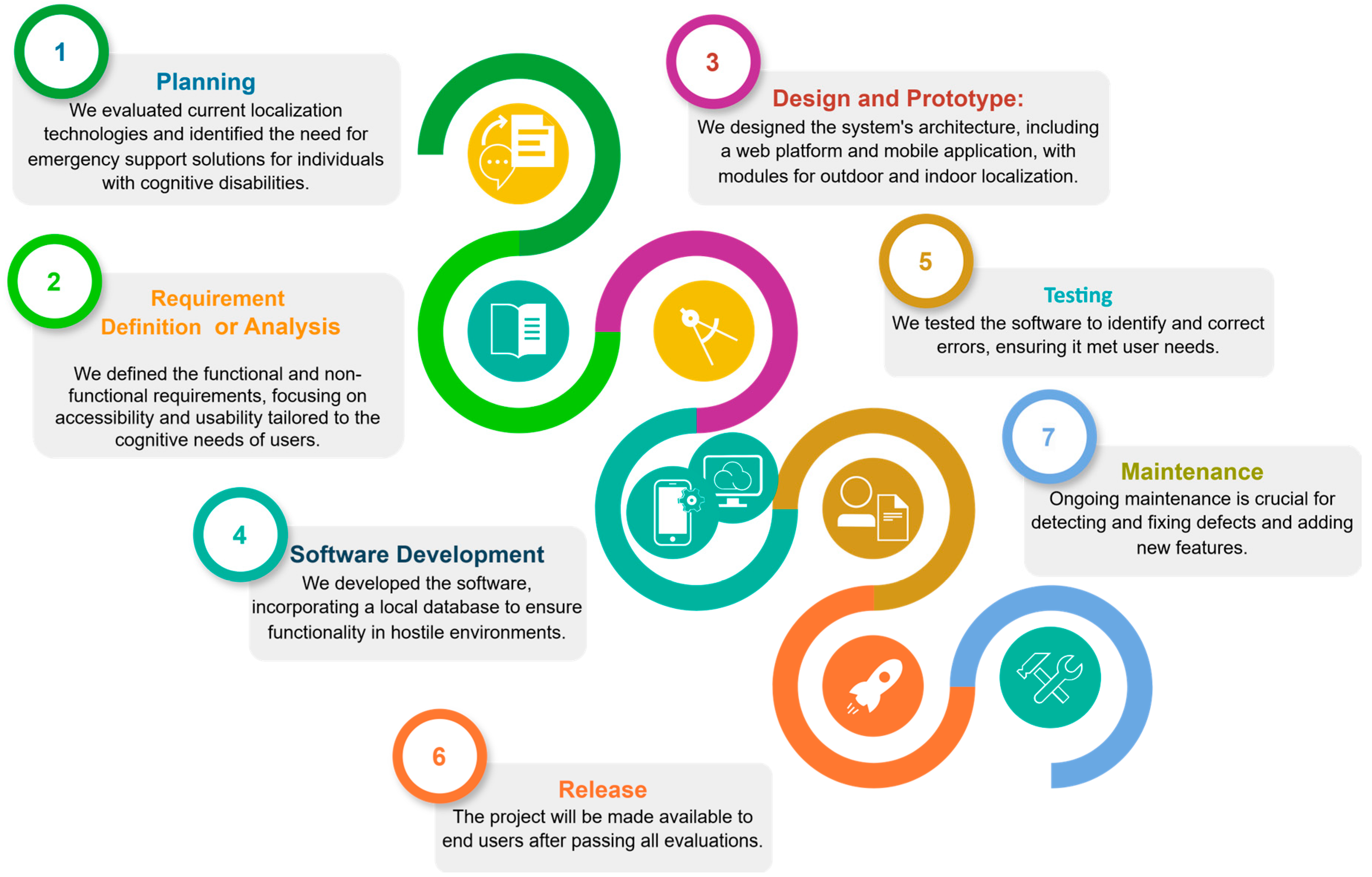
3.1.1. Development and Design of SmartRoutes
The SmartRoutes application, as mentioned earlier, has been developed on the Android platform using the object-oriented programming language Java. The foundational API version utilized for the application is Android API 33, also known as Android Tiramisu (API level 13).
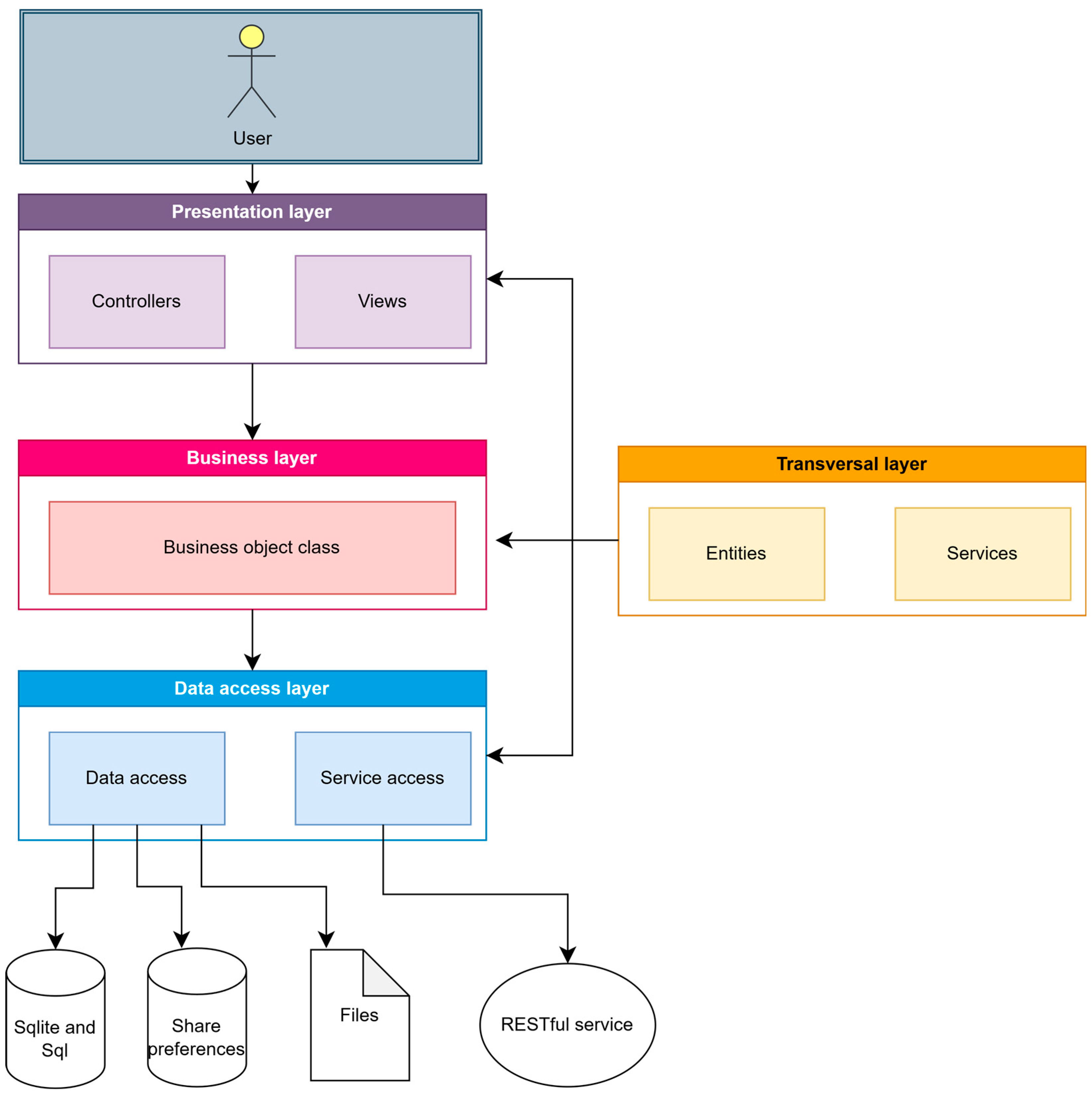
The SmartRoutes application is built upon the Android Multilayered Architecture model, defined by four interconnected layers: the application layer, framework layer, libraries, and kernel. Following the general multilayer architecture of Android, this application employs Java packages that structure the project into multiple logical units or layers. This approach aids in separating different project responsibilities.
Figure 4 presents a diagram illustrating the project responsibilities or layered architecture.
Each layer has a function that allows structuring the project:
Presentation layer: This layer is responsible for presenting information to the user. Data processing to display to the user is performed in this layer, as well as the presentation of views that constitute the application’s lifecycle flow.
Business objects layer: This layer connects the presentation layer with the data access layer, validating that the data passed as parameters comply with the rules established by the application.
Data access layer: This layer is responsible for data manipulation, in-memory storage, and retrieval and updating of information.
Cross-cutting layer: In this layer, objects and services used throughout the other layers are defined. For example, classes for a music playback service are defined within a content class in a cross-cutting package.
3.1.2. Localization and Guidance System
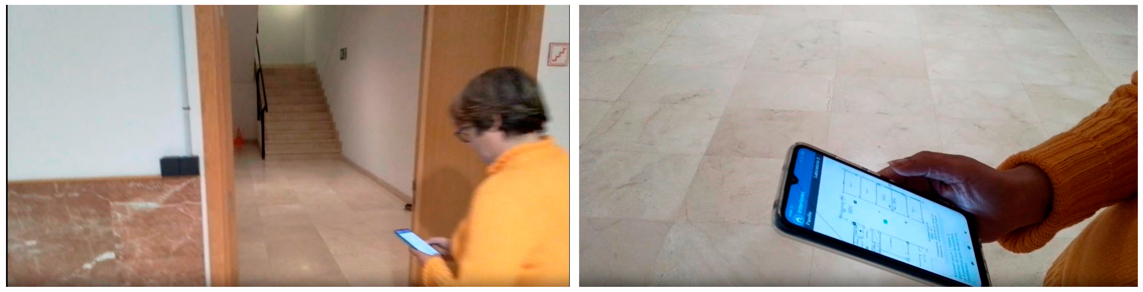
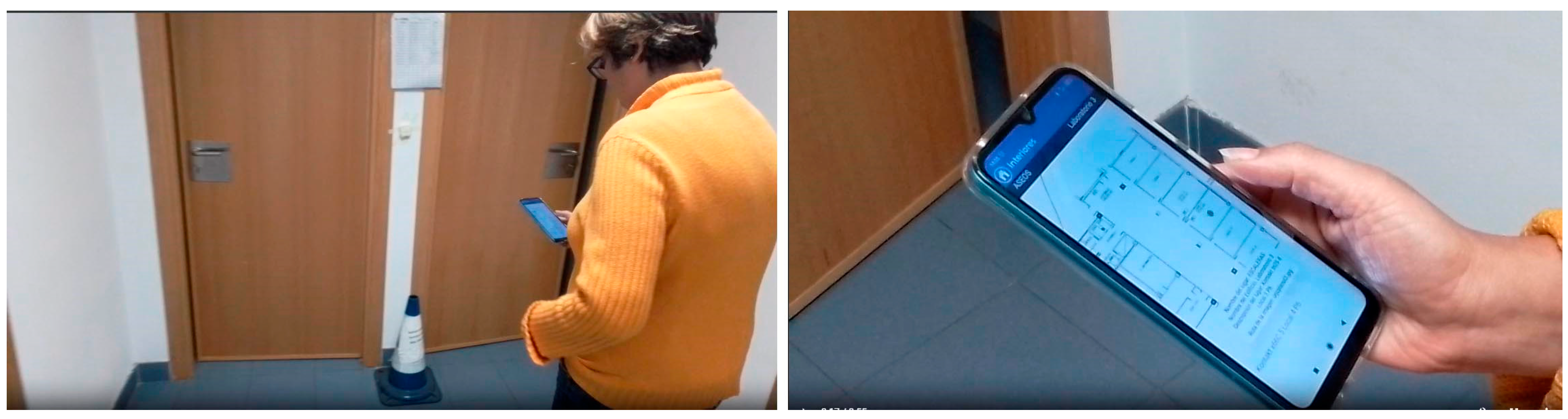
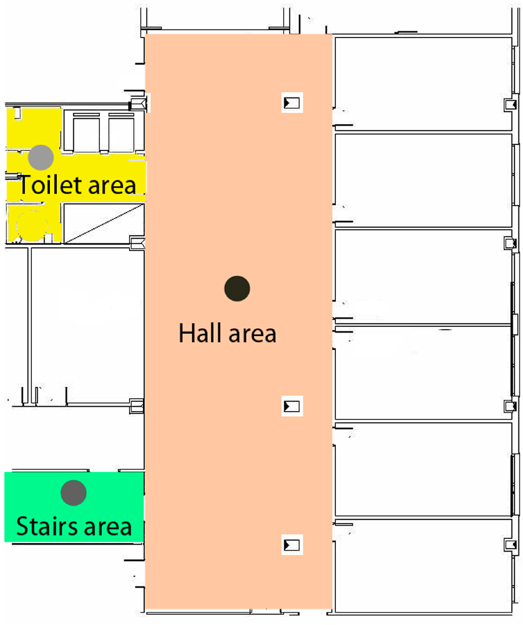
The SmartRoutes guidance solution utilizes beacons that communicate via iBeacon and Eddystone protocols through Bluetooth for user localization. These beacons have an approximate range of 10 m, but in large spaces, multiple beacons are required to ensure signal coverage across the area. It is important to note that the architecture will be evaluated in a space designed to assess localization and guidance for training daily tasks, such as work-related activities: going to the office, delivering documents, visiting the restroom, clocking in, etc., in a sequence determined by the entity aiming to assist in the user’s training. An example of deployment or evaluation is illustrated in
Figure 3, where the spaces can be further elaborated upon.
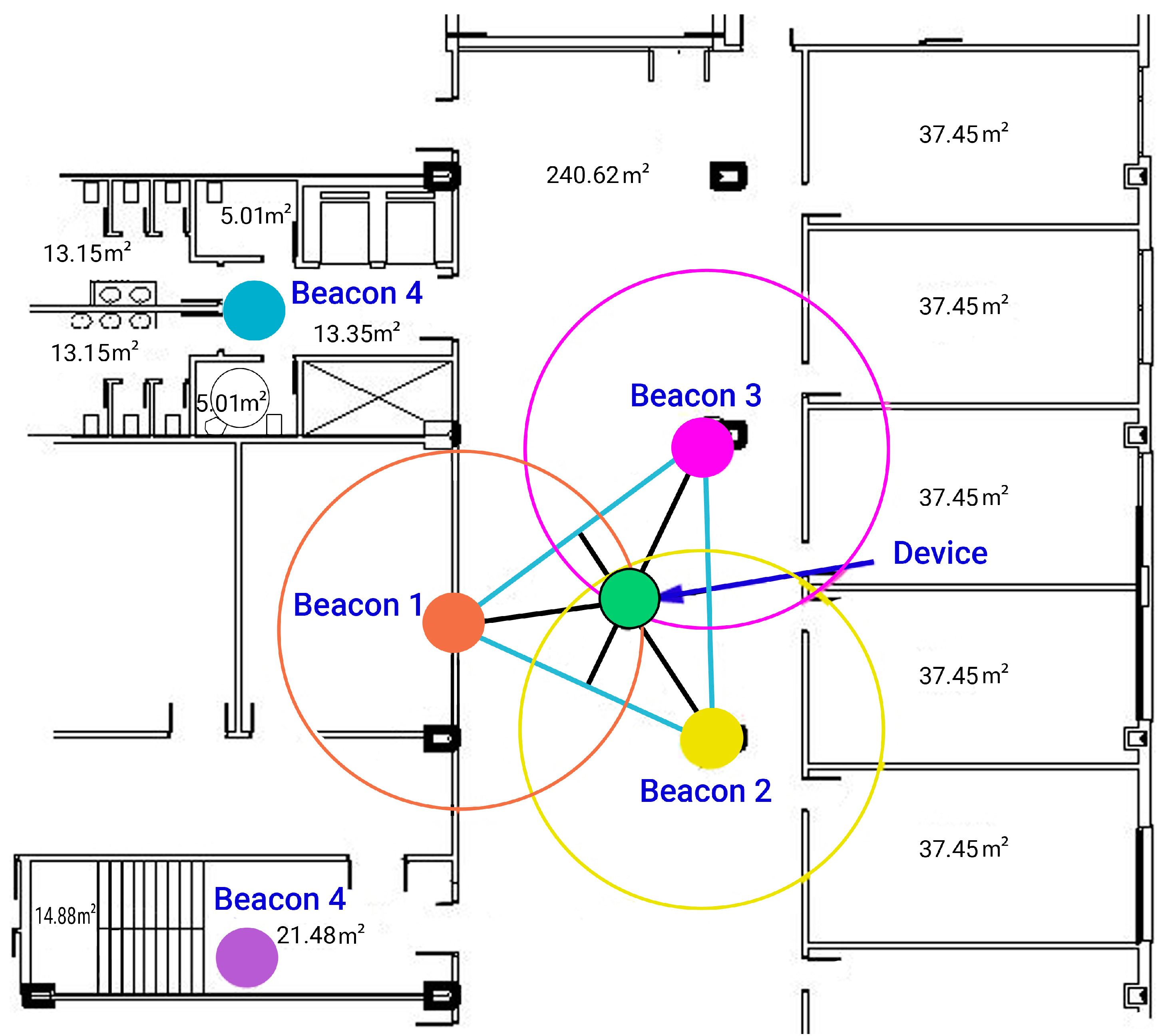
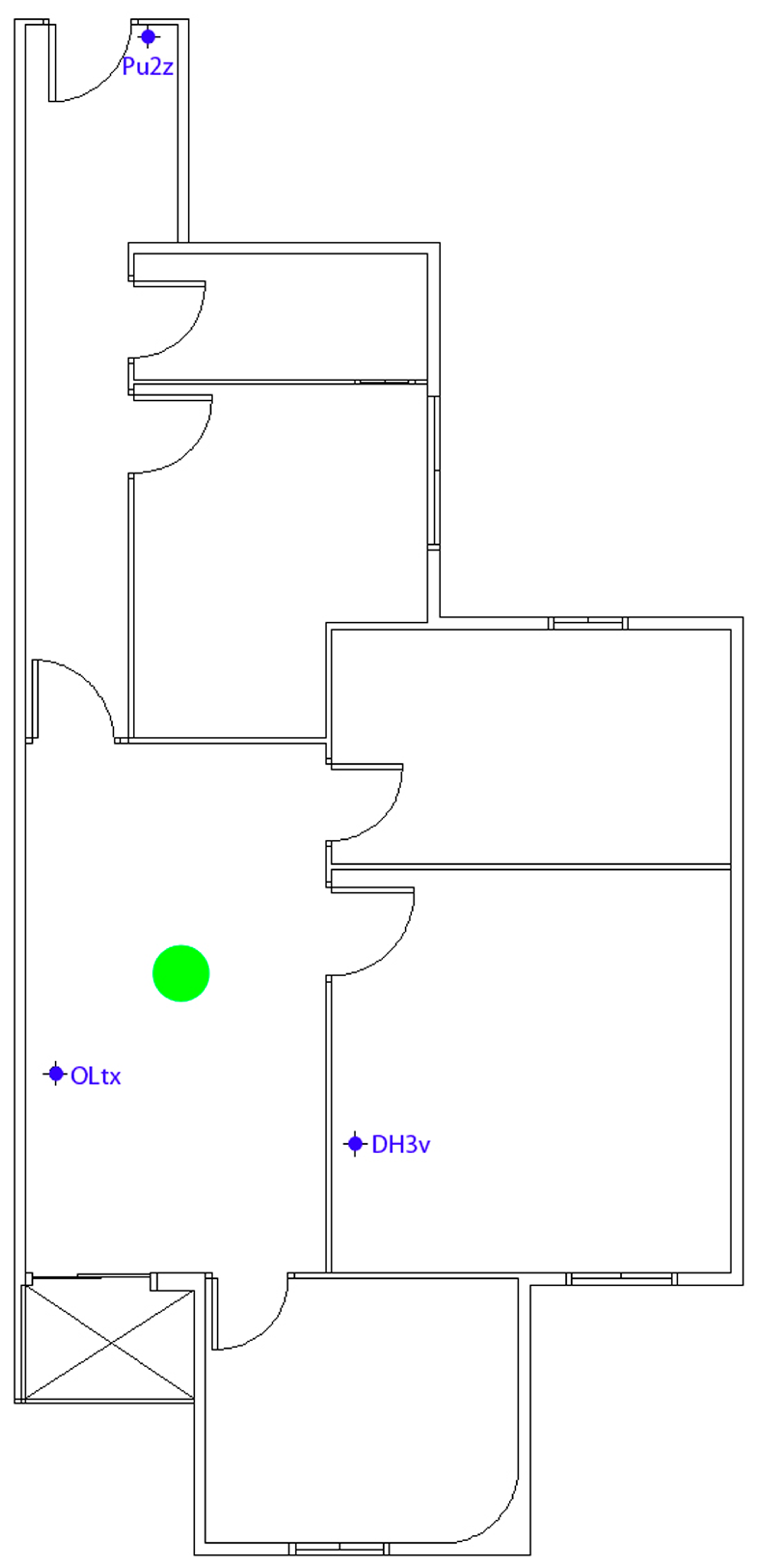
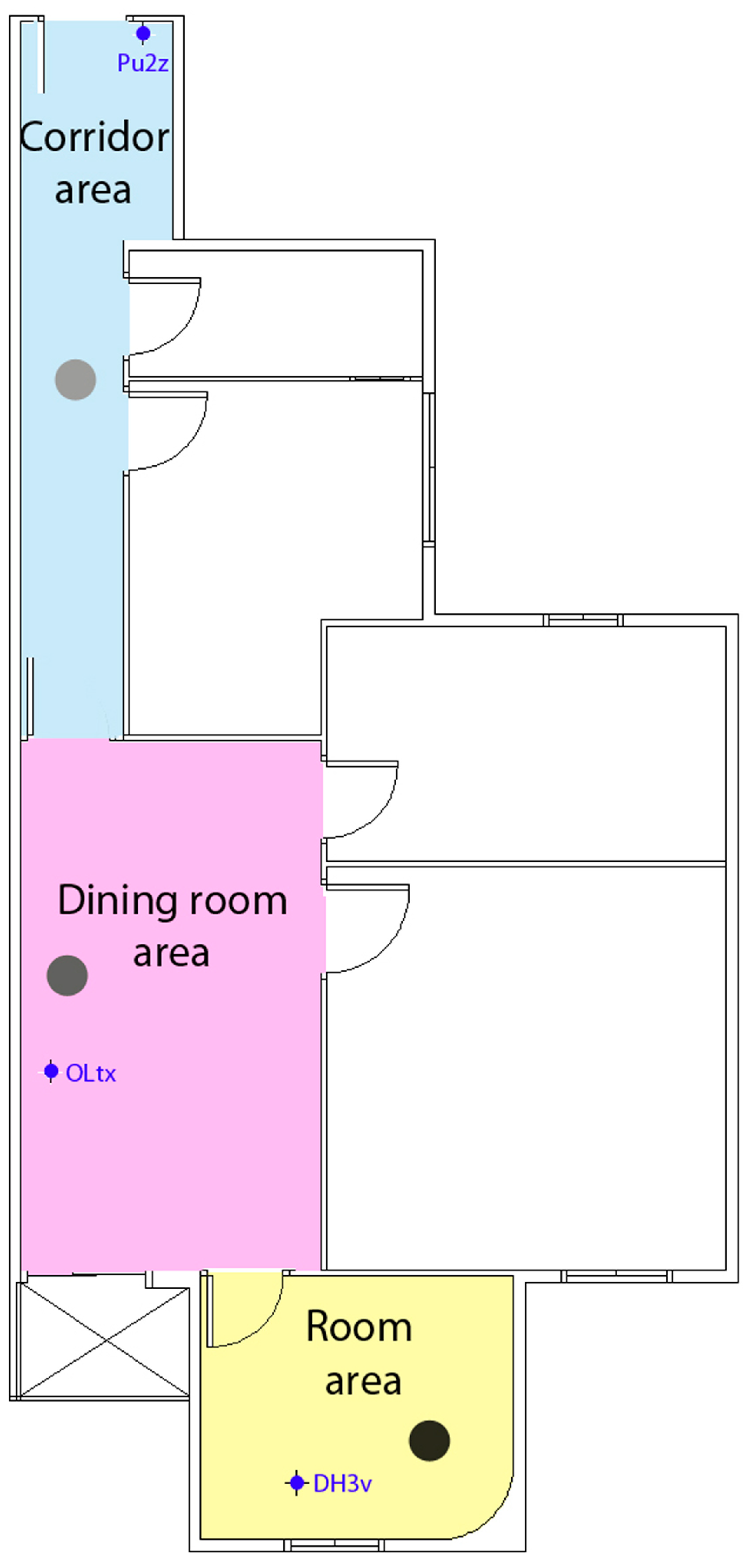
Figure 5 depicts the placement of beacons in a specific building during a test conducted with the application. The filled circles represent the effective coverage area of each beacon, indicating the maximum range within which a device can reliably detect the beacon signal. The hollow circles depict the limit of the theoretical range of beacon detection, showing areas where signal strength may start to diminish but could still provide partial coverage. In the vestibule area, measuring 240.62 m
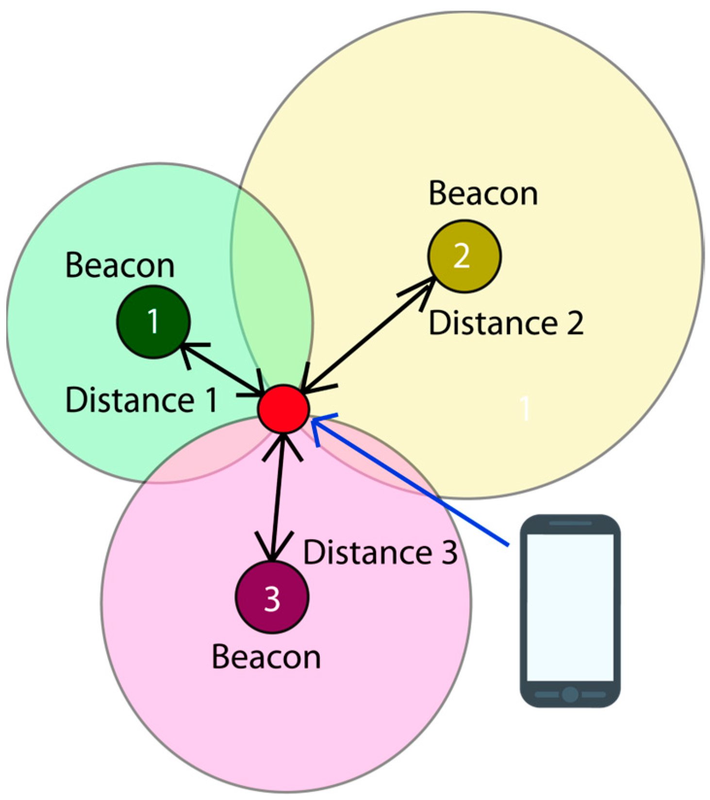
2, it was determined to position three beacons in a configuration where they are closely spaced within the 10m signal emission range. A triangle was formed based on these positions to facilitate trilateration. The centroid or barycenter of the triangle, where the three medians intersect, signifies the point where the mobile device receives the strongest RSSI intensities. In confined spaces, a single beacon is typically adequate.
This method operates with x and y coordinates, necessitating the initial measurement of distances from the mobile device to each beacon used in the trilateration method.
3.1.3. Trilateration and Intensity Calibration
To perform localization using Bluetooth, as mentioned earlier, the trilateration method has been employed. This method works with coordinates x and y, and to obtain these coordinates, it is necessary to know the distances from the mobile device to the beacon.
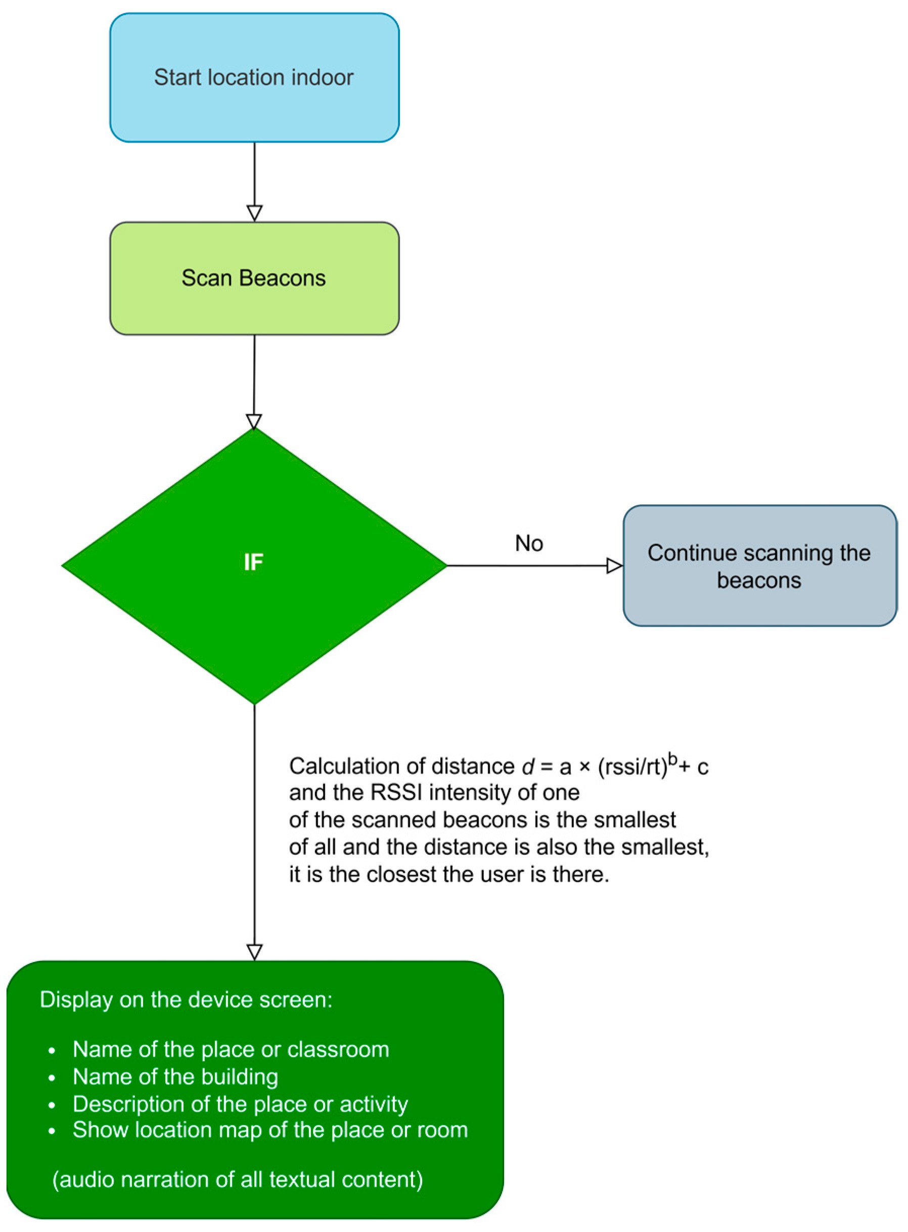
3.1.4. Calculating the Distance Between the Beacon and the Mobile Device
The calculation of the distance between both elements, beacon and mobile device, is carried out by obtaining the RSSI indicator from the beacon. Once this value is obtained, a reference value, denoted as
r, and three fixed coefficients, denoted as
a,
b, and
c, are used. These coefficients are the parameters used to simplify the system of equations and find the coordinates (
x,
y) of the unknown point. Therefore, the equation will be Equation (1):
Once the beacons and the smartphone are positioned in the designated areas, measurements of RSSI intensities from the smartphone to the beacons are taken at various distances ranging from 0.25 m to 12 m. This process is facilitated using a laser distance meter or tape measure, along with a mobile application or RSSI intensity reader device. The TX Power configuration of the beacon has been set to 7 (4 dBm).
Regarding the calculation of the distance between both elements, it is carried out by obtaining, as mentioned earlier, the RSSI indicator from the beacon.
Table 2 shows the correlation between distance and intensities.
To conduct the measurements accurately, it is essential to establish a reference value, which corresponds to the Received Signal Strength Indicator (RSSI) at a distance of one meter. Due to variations inherent in the Bluetooth range of different devices, the RSSI value recorded at one meter will serve as the baseline reference for the smartphone used in the tests. Each smartphone model may produce a distinct reference value at this distance, influenced by factors such as the chipset and the efficiency of the Bluetooth antenna. In this instance, the established reference value is −59 dBm.
Once the RSSI value is obtained, the reference ratio
rt can be calculated using Equation (2), represented as follows:
This equation represents the reference value divided by the previously obtained RSSI values at varying distances.
Table 3 and
Table 4 illustrate these calculations.
Next, the two fixed coefficients,
a and
b, are obtained; for this, a potential regression in nonlinear R will be carried out with the reference values and the RSSI data. We will assign the value (
rt) and the value in meters as
x and
y coordinates.
Table 4 shows the calculations of
x and
y values.
The power regression (PowR) for these data is Equation (3):
The coefficient values are
= 1.0229 and
= 0.1731. The values from the distance method between the beacon and the mobile device, implemented in the Java class responsible for distance calculations during the indoor beacon scanning operation in the SmartRoutes application, incorporate these coefficient values.
Table 5 presents the predicted distance calculations for the coordinates
and
.
Subsequently, an approximate distance will be determined using the coefficients
and
, which will facilitate the calculation of the coefficient
, as delineated in Equation (4). In this context,
represents the estimated distance between the beacon and the mobile device. This value is derived from the Received Signal Strength Indicator (RSSI), which quantifies the strength of the signal received by the mobile device from the beacon.
The coefficient
is a zero-intercept variable.This variable optimizes the estimation at 1 m; therefore, the calculation is performed by subtracting the actual 1-m distance and the approximate 1 m distance, as shown in Equation (5):
To finish with the data of the three coefficients
,
and
, we obtain the approximate distances.
Table 6 shows the predicted distance calculation of the
coordinate, as shown in Equations (6) and (7).
3.1.5. Trilateration Calculation
Trilateration is a geometric technique to determine the position of an object, in this case, a mobile device, by knowing its distance to three reference points, in this case, beacons.
Figure 6 shows an example of trilateration with beacons and a mobile device.
The position is calculated by determining the difference in distances between waypoints 4 and 5. For ease of identification, we label the waypoints with letters, corresponding to waypoints (
b and
c) and (
b and
a), as shown in the following equation, Equation (8).
Finally, the coordinates
and
are obtained, as demonstrated in the following equation, Equation (9):
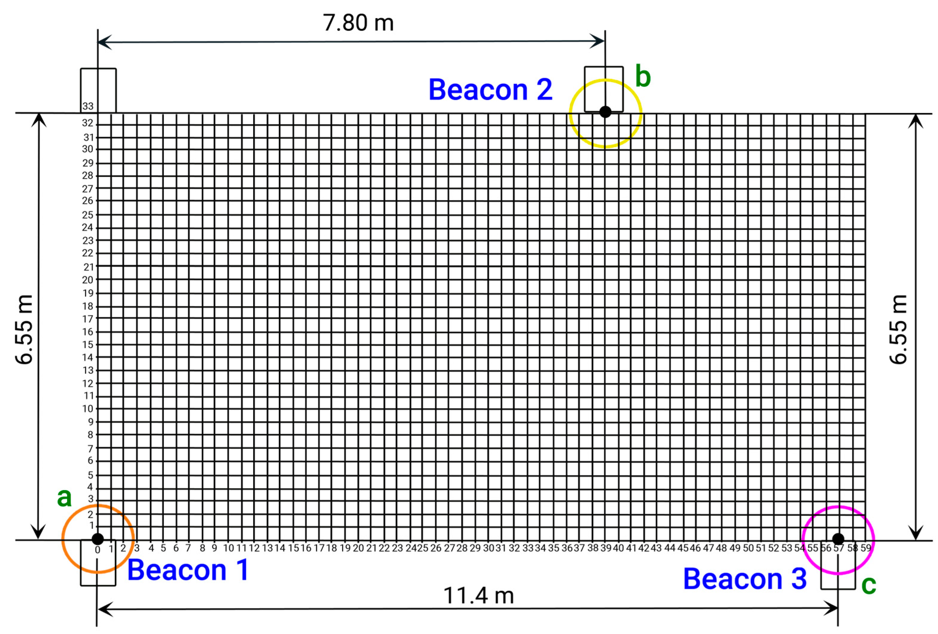
A Cartesian coordinate plane is utilized below to determine the position and location of beacons 1, 2, and 3 (or
a,
b, and
c) in the trilateration area located in the lobby of the specified building. The vertices of the triangle formed by the trilateration correspond to the coordinates (
x1,
y1), (
x2,
y2), and (
x3,
y3) of the known points from which distances are measured.
Figure 7 and
Table 7 display the Cartesian plane and the coordinate data table, with the origin point (0, 0) located at the bottom left corner of the
Figure 7.


 ,
, 


