A Compact Ultra-Wideband Millimeter-Wave Four-Port Multiple-Input Multiple-Output Antenna for 5G Internet of Things Applications


 and
and
Abstract
1. Introduction
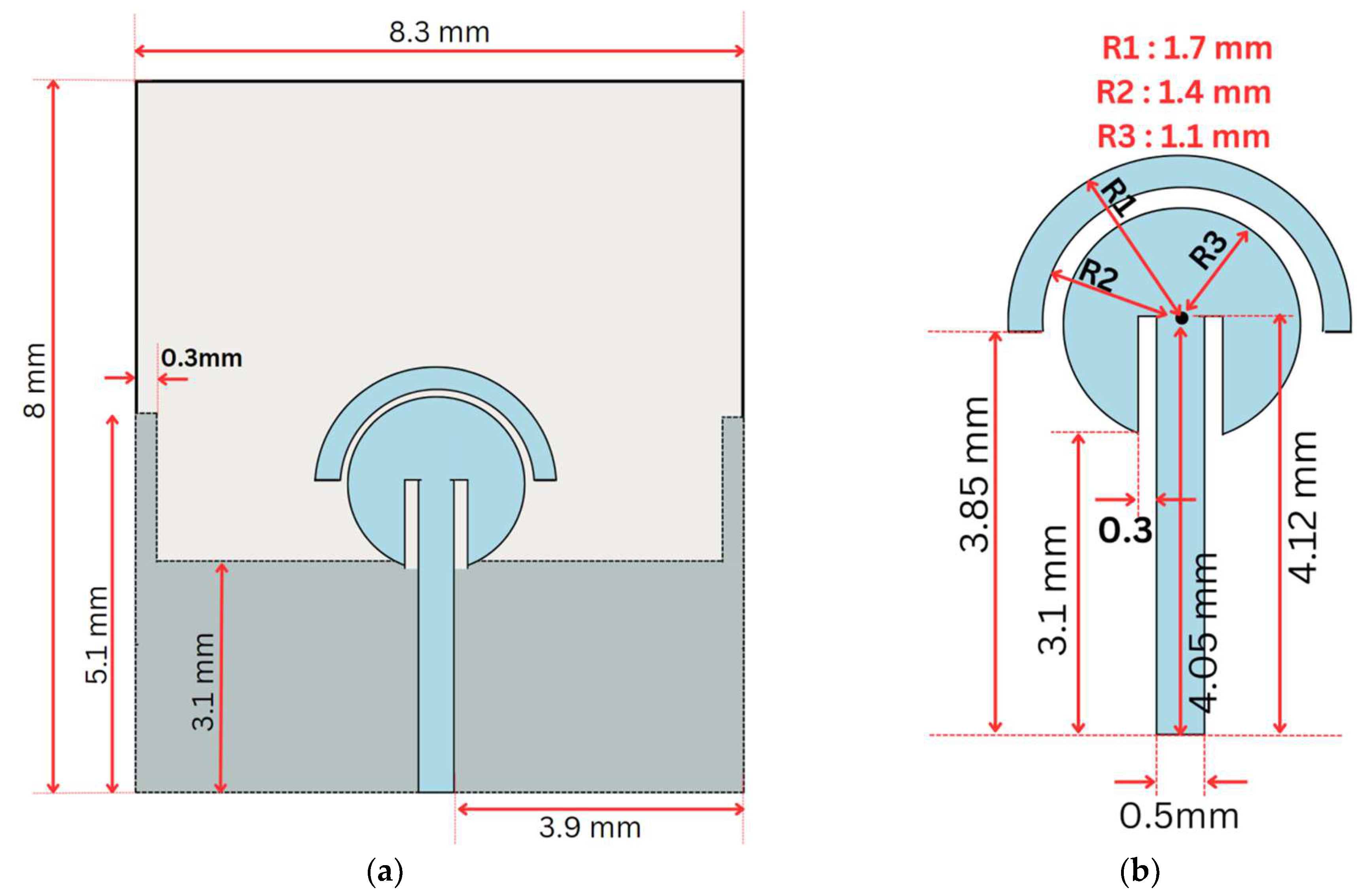
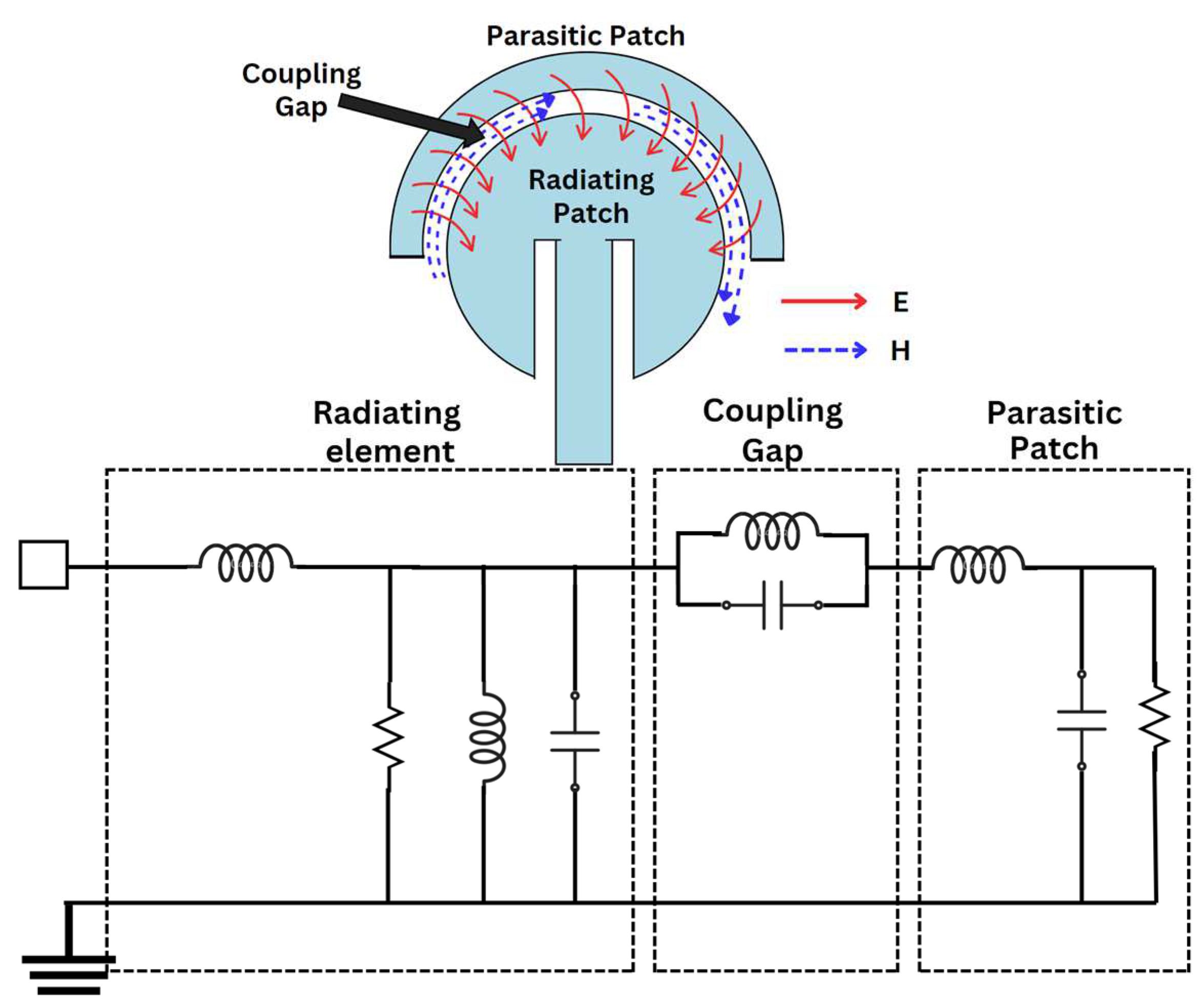
2. Antenna Design
3. Evolution
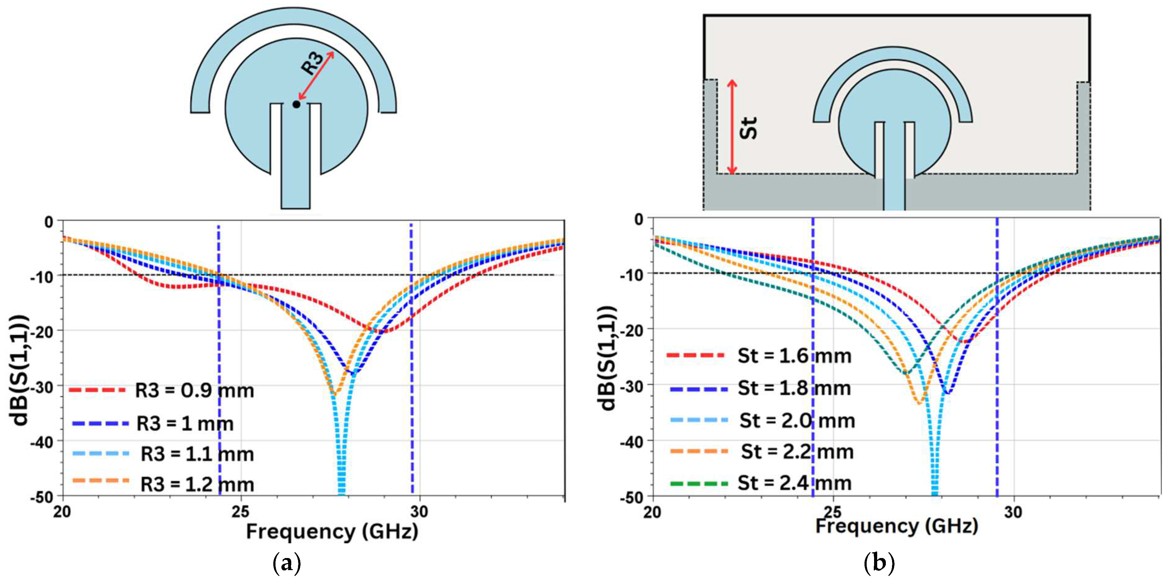
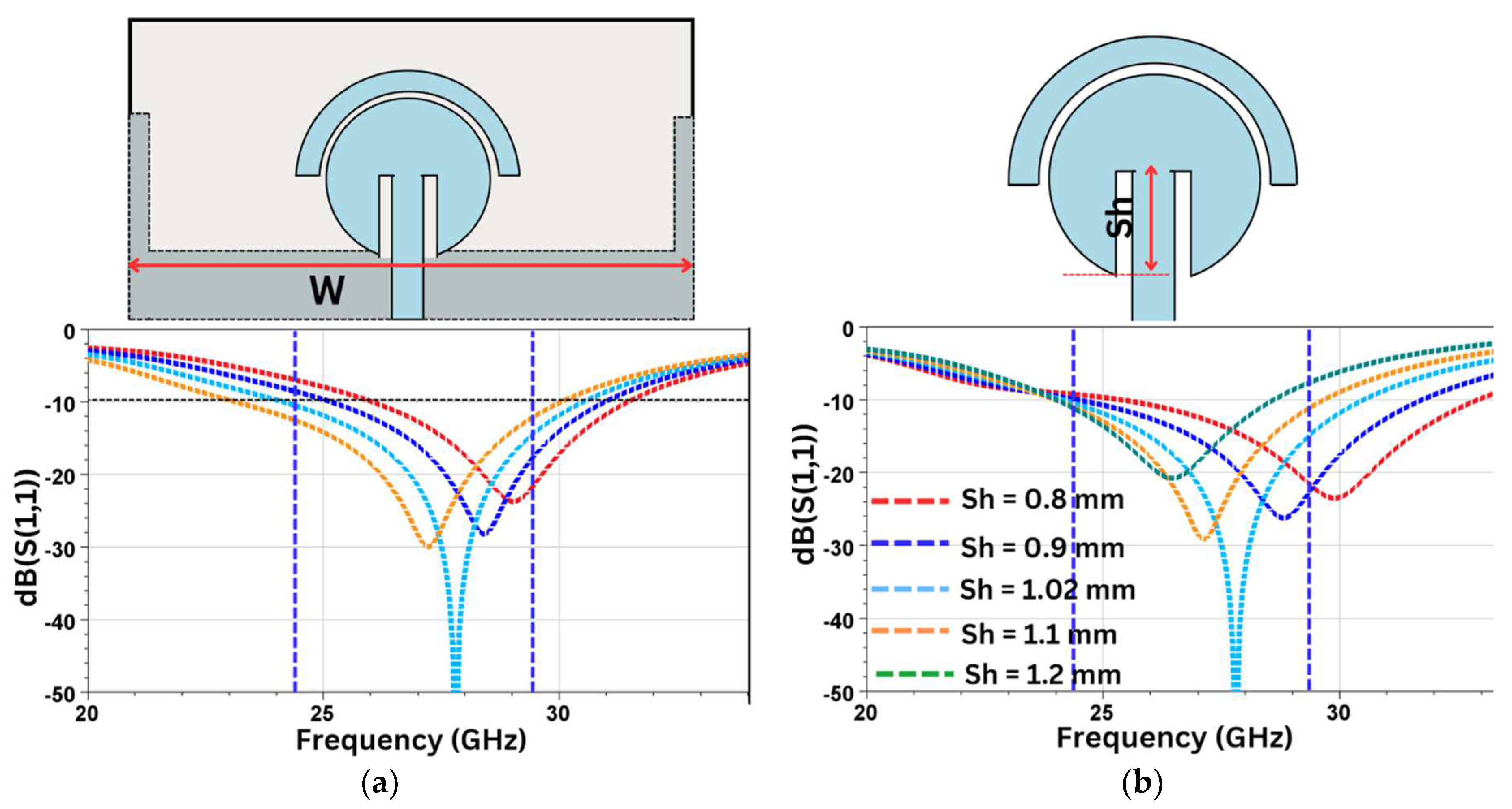
4. Parametric Analysis
5. MIMO Antenna Design
6. Results and Discussion
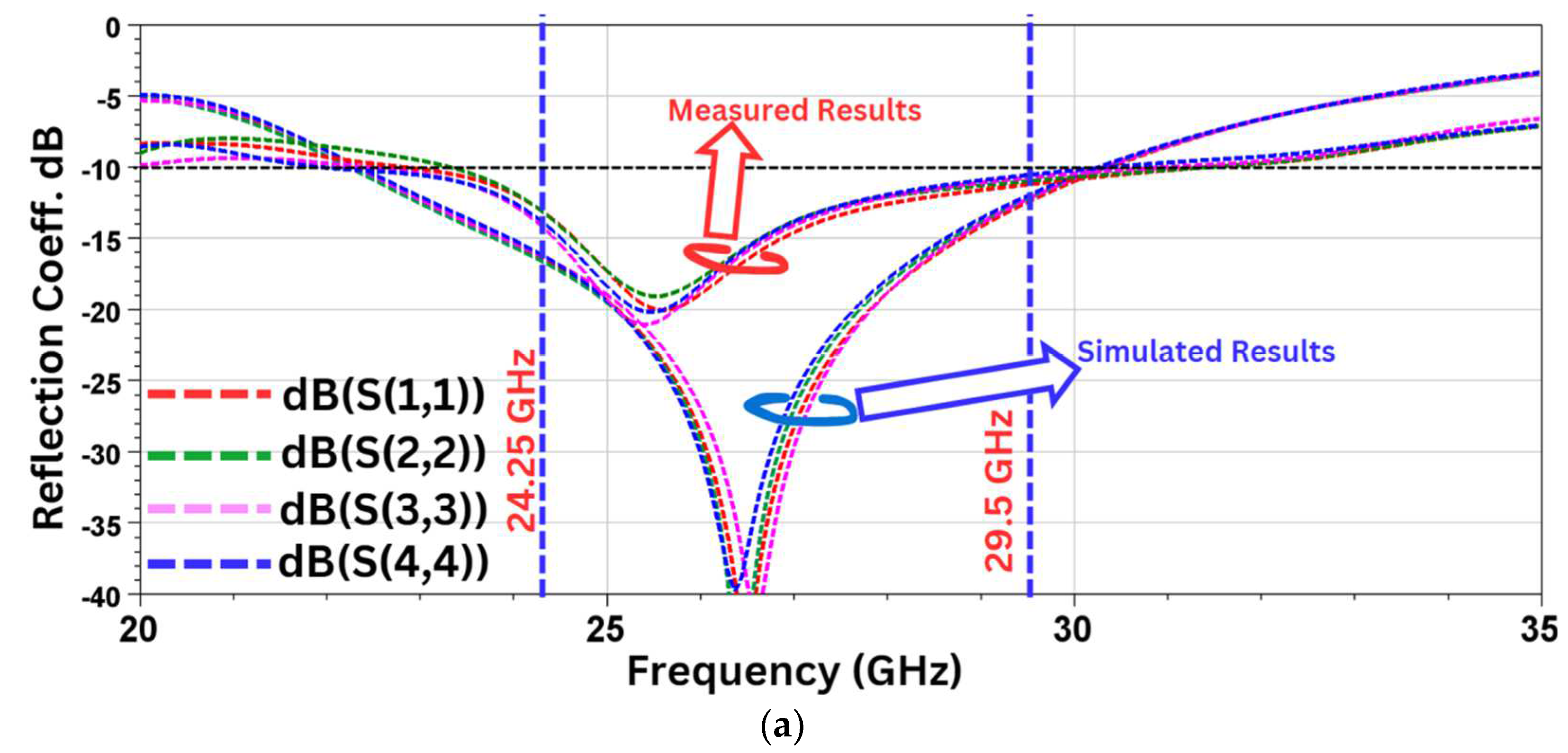
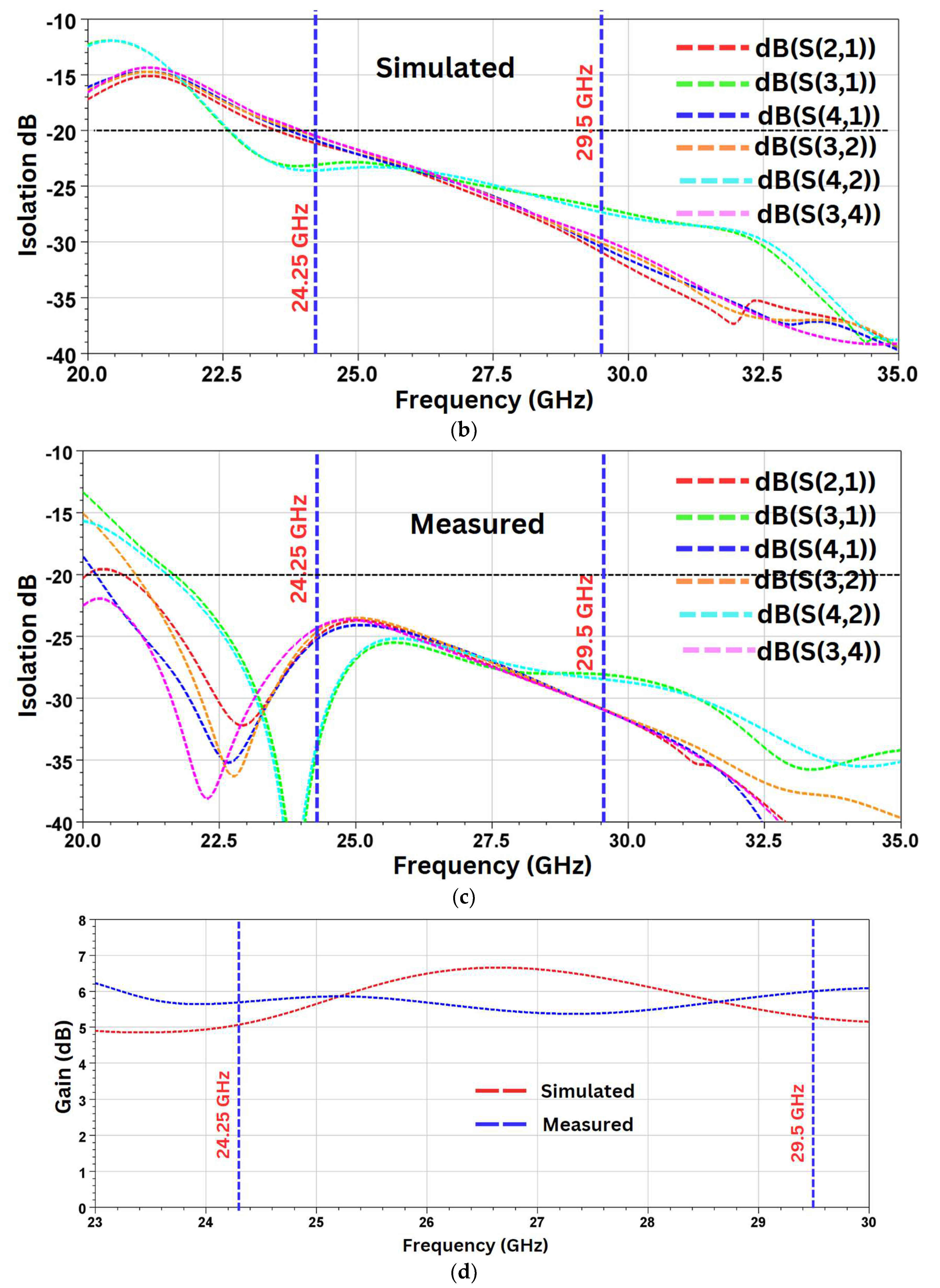
6.1. S-Parameters
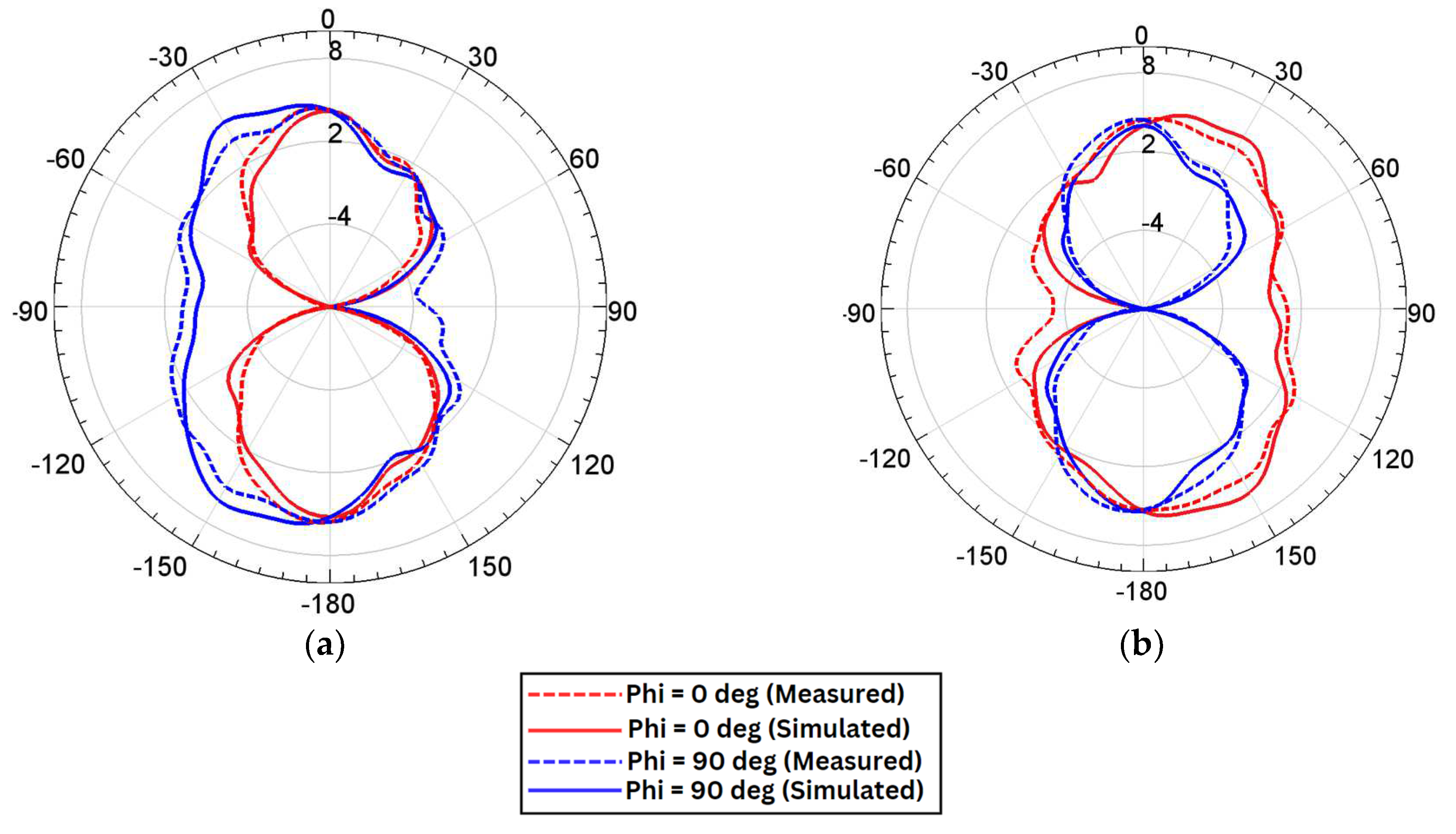
6.2. Radiation Characteristics
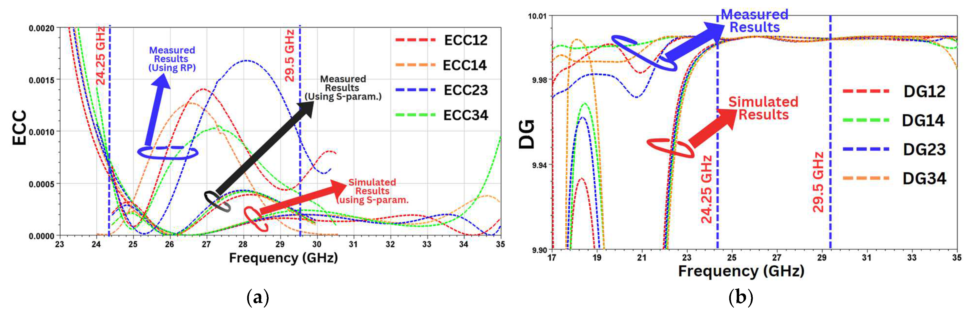
6.3. MIMO Parameters
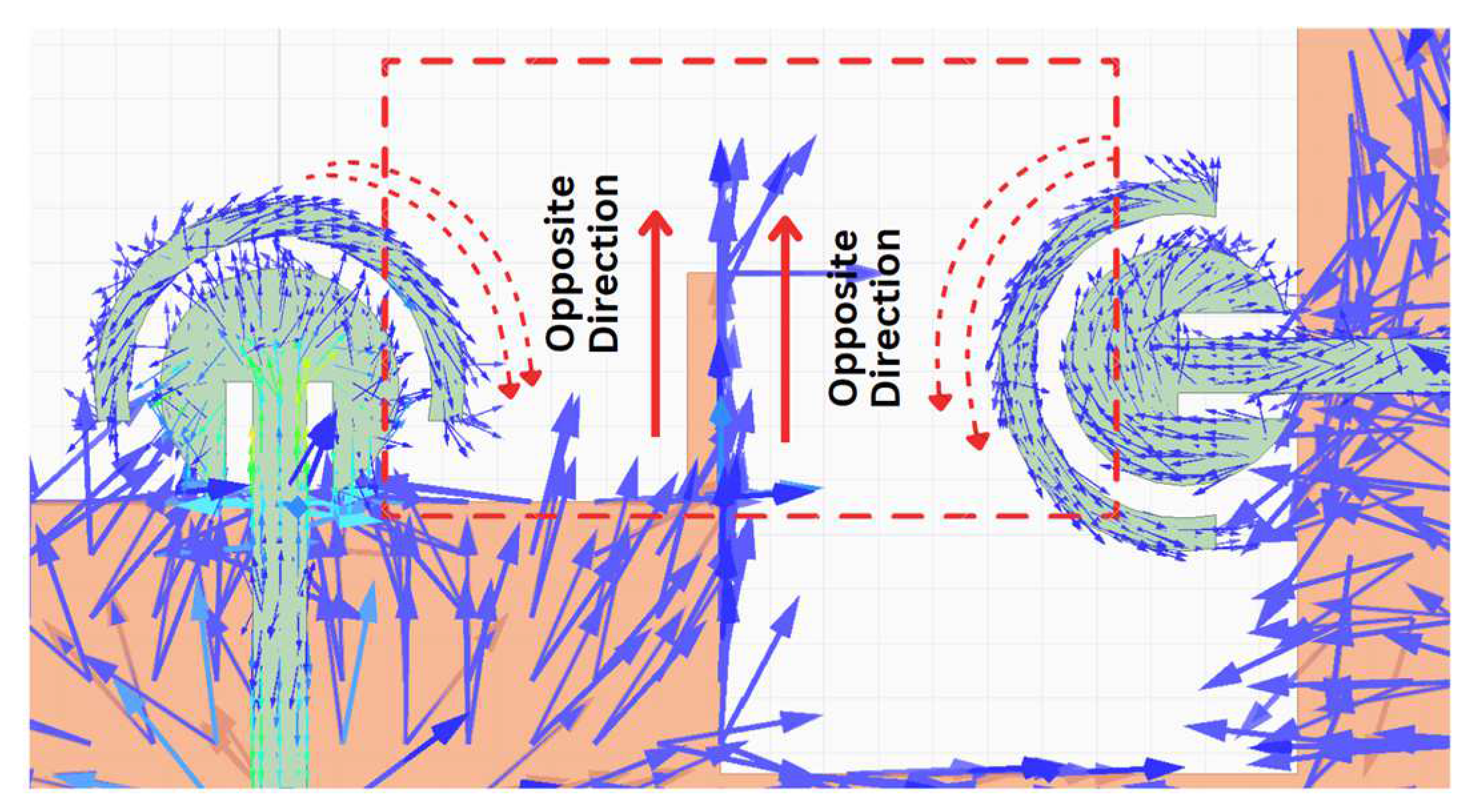
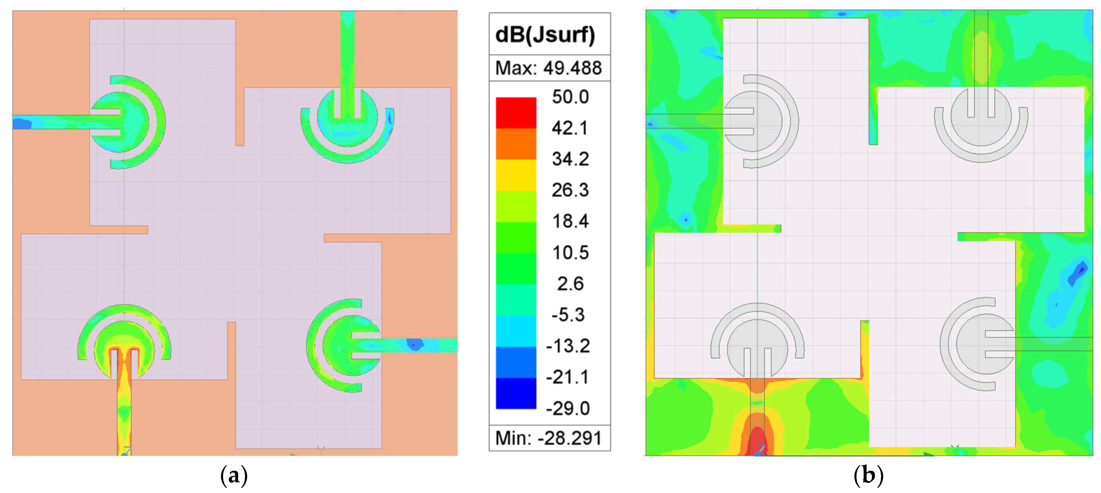
6.4. Surface Current
6.5. Comparison with Related Work
7. Conclusions
Author Contributions
Funding
Institutional Review Board Statement
Informed Consent Statement
Data Availability Statement
Conflicts of Interest
References
- Sharma, S.; Popli, R.; Singh, S.; Chhabra, G.; Saini, G.S.; Singh, M.; Sandhu, A.; Sharma, A.; Kumar, R. The Role of 6G Technologies in Advancing Smart City Applications: Opportunities and Challenges. Sustainability 2024, 16, 7039. [Google Scholar] [CrossRef]
- Sharma, S.K.; Saraswat, B.K.; Sharma, K.; Saraswat, M.; Sharma, T.K. Evaluating Multi-Platform IoT Solution for Agricultural Monitoring. In Proceedings of the 2024 2nd International Conference on Disruptive Technologies (ICDT), Greater Noida, India, 15–16 March 2024; pp. 571–576. [Google Scholar] [CrossRef]
- Rijwani, T.; Kumari, S.; Srinivas, R.; Abhishek, K.; Iyer, G.; Vara, H.; Dubey, S.; Revathi, V.; Gupta, M. Industry 5.0: A review of emerging trends and transformative technologies in the next industrial revolution. Int. J. Interact. Des. Manuf. IJIDeM 2024. [Google Scholar] [CrossRef]
- Chaudhari, R.; Shah, V.; Khanna, S.; Abhishek, K.; Vora, J. A Review on Key Technologies of Industry 4.0 in Manufacturing Sectors. In Recent Advances in Mechanical Infrastructure; Lecture Notes in Intelligent Transportation and Infrastructure; Parwani, A.K., Ramkumar, P., Abhishek, K., Yadav, S.K., Eds.; Springer: Singapore, 2022. [Google Scholar] [CrossRef]
- Salous, S.; Esposti, V.D.; Fuschini, F.; Thomae, R.S.; Mueller, R.; Dupleich, D.; Haneda, K.; Molina-Garcia-Pardo, J.M.; Pascual-Garcia, J.; Gaillot, D.P.; et al. Millimeter-Wave Propagation: Characterization and modeling toward fifth-generation systems. [Wireless Corner]. IEEE Antennas Propag. Mag. 2016, 58, 115–127. [Google Scholar] [CrossRef]
- Heath, R.W.; Gonzalez-Prelcic, N.; Rangan, S.; Roh, W.; Sayeed, A.M. An overview of signal processing techniques for millimeter-wave MIMO systems. IEEE J. Sel. Top. Signal Process. 2016, 10, 436–453. [Google Scholar] [CrossRef]
- Bhadravathi Ghouse, P.S.; Mane, P.R.; Ali, T.; Golapuram Dattathreya, G.S.; Puthenveettil Gopi, S.; Pathan, S.; Anguera, J. A Low-Profile Circularly Polarized Millimeter-Wave Broadband Antenna Analyzed with a Link Budget for IoT Applications in an Indoor Scenario. Sensors 2024, 24, 1569. [Google Scholar] [CrossRef]
- Sun, S.; Rappaport, T.; Heath, R.; Nix, A.; Rangan, S. Mimo for millimeter-wave wireless communications: Beamforming, spatial multiplexing, or both? IEEE Commun. Mag. 2014, 52, 110–121. [Google Scholar] [CrossRef]
- Kumaravelu, V.B.; Jaiswal, G.; Gudla, V.V.; Ramachandra Reddy, G.; Murugadass, A. Modified spatial modulation: An alternate to spatial multiplexing for 5G-based compact wireless devices. Arab. J. Sci. Eng. 2019, 44, 6693–6709. [Google Scholar] [CrossRef]
- Lin, Y.; Jin, S.; Matthaiou, M.; You, X. Transceiver Design With UCD-Based Hybrid Beamforming for Millimeter Wave Massive MIMO. IEEE Trans. Commun. 2019, 67, 4047–4061. [Google Scholar] [CrossRef]
- Zhang, R.; Wu, X.; Lou, Y.; Yan, F.G.; Zhou, Z.; Wu, W.; Yuen, C. Channel Training-Aided Target Sensing for Terahertz Integrated Sensing and Massive MIMO Communications. IEEE Internet Things J. 2024. early access. [Google Scholar] [CrossRef]
- Lin, Y.; Jin, S.; Matthaiou, M.; You, X. Tensor-Based Algebraic Channel Estimation for Hybrid IRS-Assisted MIMO-OFDM. IEEE Trans. Wirel. Commun. 2021, 20, 3770–3784. [Google Scholar] [CrossRef]
- Zhang, R.; Cheng, L.; Zhang, W.; Guan, X.; Cai, Y.; Wu, W.; Zhang, R. Channel Estimation for Movable-Antenna MIMO Systems Via Tensor Decomposition. arXiv 2024, arXiv:2407.18773. [Google Scholar] [CrossRef]
- Zhu, L.; Ma, W.; Zhang, R. Modeling and Performance Analysis for Movable Antenna Enabled Wireless Communications. IEEE Trans. Wirel. Commun. 2022, 23, 6234–6250. [Google Scholar] [CrossRef]
- Zhang, S.; Pedersen, G.F. Mutual coupling reduction for UWB MIMO antennas with a wideband neutralization line. IEEE Antennas Wirel. Propag. Lett. 2016, 15, 166–169. [Google Scholar] [CrossRef]
- Satam, V.; Nema, S. Two element compact UWB diversity antenna with combination of DGS and parasitic elements. Wirel. Pers. Commun. 2018, 98, 2901–2911. [Google Scholar] [CrossRef]
- Kumar, P.; Pathan, S.; Kumar, O.P.; Vincent, S.; Nanjappa, Y.; Kumar, P.; Shetty, A.; Ali, T. Design of a six-port compact UWB MIMO antenna with a distinctive DGS for improved isolation. IEEE Access 2022, 10, 112964–112974. [Google Scholar] [CrossRef]
- Alibakhshikenari, M.; Babaeian, F.; Virdee, B.S.; Aissa, S.; Azpilicueta, L.; See, C.H.; Althuwayb, A.A.; Huynen, I.; Abd-Alhameed, R.A.; Falcone, F.; et al. A comprehensive survey on “various decoupling mechanisms with focus on metamaterial and metasurface principles applicable to SAR and MIMO antenna systems. IEEE Access 2020, 8, 192965–193004. [Google Scholar] [CrossRef]
- Shome, P.P.; Khan, T.; Kishk, A.A.; Antar, Y.M.M. Quad-element MIMO antenna system using half-cut miniaturized UWB antenna for IoT-based smart home digital entertainment network. IEEE Internet Things J. 2023, 10, 17964–17976. [Google Scholar] [CrossRef]
- Kaiser, T.; Zheng, F.; Dimitrov, E. An overview of ultra-wide-band systems with MIMO. Proc. IEEE 2009, 97, 285–312. [Google Scholar] [CrossRef]
- Nadeem, I.; Choi, D.-Y. Study on mutual coupling reduction technique for MIMO antennas. IEEE Access 2019, 7, 563–586. [Google Scholar] [CrossRef]
- Kumar, P.; Pai, M.M.M.; Ali, T. Design and analysis of multiple antenna structures for ultrawide bandwidth. Telecommun. Radio Eng. 2021, 80, 41–53. [Google Scholar] [CrossRef]
- Tripathi, S.; Mohan, A.; Yadav, S. A compact octagonal fractal UWBMIMO antenna with WLAN band-rejection. Microw. Opt. Technol. Lett. 2015, 57, 1919–1925. [Google Scholar] [CrossRef]
- Wu, L.; Cao, X.; Yang, B. Design and analysis of a compact UWB-MIMO antenna with four notched bands. Prog. Electromagn. Res. M 2022, 108, 127–137. [Google Scholar] [CrossRef]
- Singh, H.V.; Tripathi, S. Compact UWB MIMO antenna with fork-shaped stub with vias based coupling current steering (VBCCS) to enhance isolation using CMA. AEU-Int. J. Electron. Commun. 2021, 129, 153550. [Google Scholar] [CrossRef]
- Huang, H.; Xiao, S. Compact MIMO antenna for Bluetooth WiMAX WLAN and UWB applications. Microw. Opt. Technol. Lett. 2016, 58, 783–787. [Google Scholar] [CrossRef]
- Guichi, F.; Challal, M. A compact 2-element symmetrically fed MIMO antenna with a ground isolation stub for ultra-wideband communication systems. Wirel. Pers. Commun. 2023, 128, 131–146. [Google Scholar] [CrossRef]
- Farahat, A.E.; Hussein, K.F.A. Dual-Band (28/38 GHz) Wideband MIMO Antenna for 5G Mobile Applications. IEEE Access 2022, 10, 32213–32223. [Google Scholar] [CrossRef]
- Balanis, C.A. Antenna Theory: Analysis and Design, 3rd ed.; John Wiley & Sons: Hoboken, NJ, USA, 2005. [Google Scholar]
- Kapoor, A.; Mishra, R.; Kumar, P. Wideband miniaturized patch radiator for Sub-6GHz 5G devices. Heliyon 2021, 7, e07931. [Google Scholar] [CrossRef]
- Paul, L.C.; Hye, S.A.; Rani, T.; Hossain, I.; Karaaslan, M.; Ghosh, P.; Saha, H.K. A compact wrench-shaped patch antenna with a slotted parasitic element and semi-circular ground plane for 5G communication. E-Prime Adv. Electr. Eng. Electron. Energy 2023, 6, 100334. [Google Scholar] [CrossRef]
- Feng, S.; Zhang, L.; Yu, H.-W.; Zhang, Y.-X.; Jiao, Y.-C. A Single-Layer Wideband Differential-Fed Microstrip Patch Antenna with Complementary Split-Ring Resonators Loaded. IEEE Access 2019, 7, 132041–132048. [Google Scholar] [CrossRef]
- Kim, S.-W.; Yu, H.-G.; Choi, D.-Y. Analysis of Patch Antenna with Broadband Using Octagon Parasitic Patch. Sensors 2021, 21, 4908. [Google Scholar] [CrossRef]
- Elsharkawy, R.R.; Hussein, K.A.; Farahat, A.E. Dual-Band (28/38 GHz) Compact MIMO Antenna System for Millimeter-Wave Applications. J. Infrared Millim. Terahertz Waves 2023, 44, 1016–1037. [Google Scholar] [CrossRef]
- Sharawi, M.S. Current Misuses and Future Prospects for Printed Multiple-Input, Multiple-Output Antenna Systems [Wireless Corner]. IEEE Antennas Propag. Mag. 2017, 59, 162–170. [Google Scholar] [CrossRef]
- Mak, A.C.K.; Rowell, C.R.; Murch, R.D. Isolation enhancement between two closely packed antennas. IEEE Trans. Antennas Propag. 2008, 56, 3411–3419. [Google Scholar] [CrossRef]
- Mazloum, J.; Ghorashi, S.A.; Ojaroudi, M.; Ojaroudi, N. Compact Triple-Band S-Shaped Monopole Diversity Antenna for MIMO Applications. Appl. Comput. Electromagn. Soc. J. 2015, 30, 975–980. [Google Scholar]
- Kim, S.H.; Chung, J.Y. Analysis of the Envelope Correlation Coefficient of MIMO Antennas Connected with Suspended Lines. J. Electromagn. Eng. Sci. 2020, 20, 83–90. [Google Scholar] [CrossRef]
- Kumar, A.; Ansari, A.Q.; Kanaujia, B.K.; Kishor, J. High isolation compact four-port MIMO antenna loaded with CSRR for multiband applications. Frequenz 2018, 72, 415–427. [Google Scholar] [CrossRef]
- Usman, M.; Kobal, E.; Nasir, J.; Zhu, Y.; Yu, C.; Zhu, A. Compact SIW Fed Dual-Port Single Element Annular Slot MIMO Antenna for 5G mmWave Applications. IEEE Access 2021, 9, 91995–92002. [Google Scholar] [CrossRef]
- Kobal, E.; Liu, R.-J.; Yu, C.; Zhu, A. A High Isolation, Low-Profile, Triple-Port SIW Based Annular Slot Antenna for Millimeter-Wave 5G MIMO Applications. IEEE Access 2022, 10, 89458–89464. [Google Scholar] [CrossRef]
- Hussain, N.; Jeong, M.-J.; Park, J.; Kim, N. A broadband circularly polarized Fabry–Perot resonant antenna using a single-layered PRS for 5G MIMO applications. IEEE Access 2019, 7, 42897–42907. [Google Scholar] [CrossRef]
- Khalid, M.; Naqvi, S.I.; Hussain, N.; Rahman, M.; Fawad; Mirjavadi, S.S.; Khan, M.J.; Amin, Y. 4-port MIMO antenna with defected ground structure for 5G millimeter wave applications. Electronics 2020, 9, 71. [Google Scholar] [CrossRef]
- Zhang, Y.; Deng, J.-Y.; Li, M.-J.; Sun, D.; Guo, L.-X. A MIMO dielectric resonator antenna with improved isolation for 5G mm-wave applications. IEEE Antennas Wirel. Propag. Lett. 2019, 18, 747–751. [Google Scholar] [CrossRef]
- Sim, C.Y.D.; Lo, J.J.; Chen, Z.N. Design of a Broadband Millimeter-Wave Array Antenna for 5G Applications. IEEE Antennas Wirel. Propag. Lett. 2023, 22, 1030–1034. [Google Scholar] [CrossRef]


| Ref. | Structure Type | Center Freq./Band | Bandwidth (GHz) | Size (mm) | No of Ports | Peak Gain (dBi) | DG (dB) | ECC | Min Isolation |
|---|---|---|---|---|---|---|---|---|---|
| [40] | Air-filled slot | 28 GHz | 0.4 | 33 × 27.5 × 0.76 | 2 | 6.9 | 9.9998 | 0.001 | 30 |
| [41] | SIW-based | 28 GHz | 0.55 | 26 × 26 × 0.76 | 3 | 4.71 | - | <0.002 | >30 |
| [42] | Fabry–Perot (2-layer) | 28 GHz | 7 | 19 ×19 × 7.608 | 4 | 14.1 | - | <0.008 | >25 |
| [43] | Defected ground array | 28 GHz | 4.1 | 30 × 35.5 × 0.76 | 4 | 8.02 | >9.96 | <0.01 | 17 |
| [44] | Dielectric resonator | 28 GHz | 0.85 | 20 × 20 × 2.54 | 2 | 8 | 9.9 | 0.13 | 24 |
| [45] | Coplanar feed patch | n257/n258/n261 (23–30.5 GHz) | 7.5 | 26 × 5 × 1.524 | 4 | 9.76 | - | - | >16 |
| Our Work | Circular Patch | 28 GHz | 5.25 | 16.2 × 16.2 × 0.254 | 4 | 6.09 | >9.99 | <0.002 | >23.5 |
Disclaimer/Publisher’s Note: The statements, opinions and data contained in all publications are solely those of the individual author(s) and contributor(s) and not of MDPI and/or the editor(s). MDPI and/or the editor(s) disclaim responsibility for any injury to people or property resulting from any ideas, methods, instructions or products referred to in the content. |
© 2024 by the authors. Licensee MDPI, Basel, Switzerland. This article is an open access article distributed under the terms and conditions of the Creative Commons Attribution (CC BY) license (https://creativecommons.org/licenses/by/4.0/).
Share and Cite
Sharma, A.; Sharma, S.; Sharma, V.; Wadhwa, G.; Kumar, R. A Compact Ultra-Wideband Millimeter-Wave Four-Port Multiple-Input Multiple-Output Antenna for 5G Internet of Things Applications. Sensors 2024, 24, 7153. https://doi.org/10.3390/s24227153
Sharma A, Sharma S, Sharma V, Wadhwa G, Kumar R. A Compact Ultra-Wideband Millimeter-Wave Four-Port Multiple-Input Multiple-Output Antenna for 5G Internet of Things Applications. Sensors. 2024; 24(22):7153. https://doi.org/10.3390/s24227153
Chicago/Turabian StyleSharma, Ashutosh, Sanjeev Sharma, Vikas Sharma, Girish Wadhwa, and Rajeev Kumar. 2024. "A Compact Ultra-Wideband Millimeter-Wave Four-Port Multiple-Input Multiple-Output Antenna for 5G Internet of Things Applications" Sensors 24, no. 22: 7153. https://doi.org/10.3390/s24227153
APA StyleSharma, A., Sharma, S., Sharma, V., Wadhwa, G., & Kumar, R. (2024). A Compact Ultra-Wideband Millimeter-Wave Four-Port Multiple-Input Multiple-Output Antenna for 5G Internet of Things Applications. Sensors, 24(22), 7153. https://doi.org/10.3390/s24227153