
Sensor-to-Bone Calibration with the Fusion of IMU and Bi-Plane X-rays

 , , , , , and
Abstract
1. Introduction
2. Materials and Methods
2.1. Population
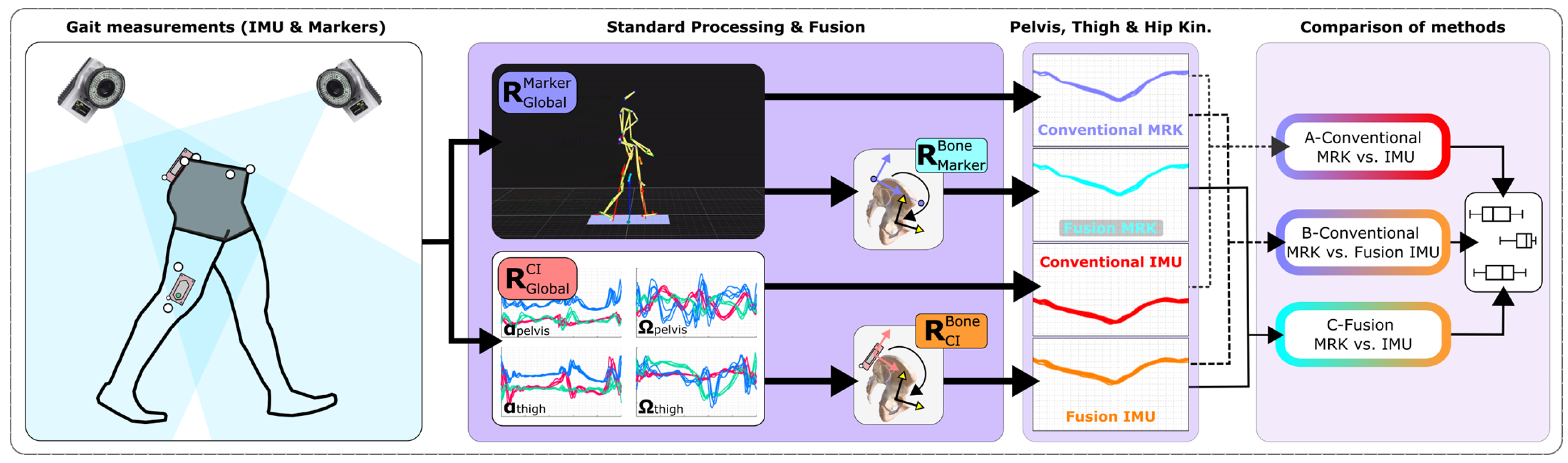
2.2. Measurements Protocol
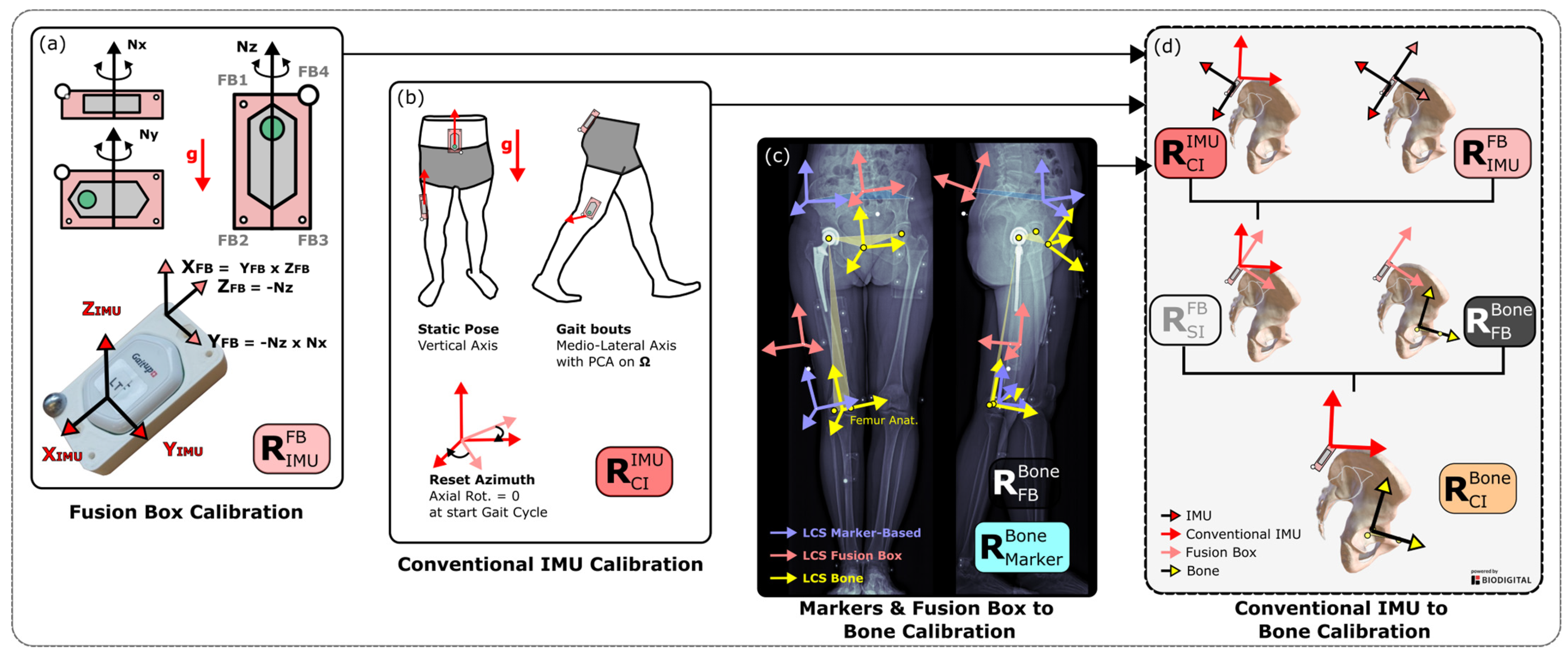
2.3. Fusion Box
2.4. Rotation Matrices of the IMU-Based Methods
2.4.1. Conventional Method: Sensor-to-Segment Calibration
2.4.2. Fusion Method: Sensor-to-Bone Calibration
2.5. Rotation Matrices of the Marker-Based Methods
2.5.1. Conventional Method
2.5.2. Fusion Method: Markers-to-Bone
2.6. Segment and Joint Angles
2.7. Analysis
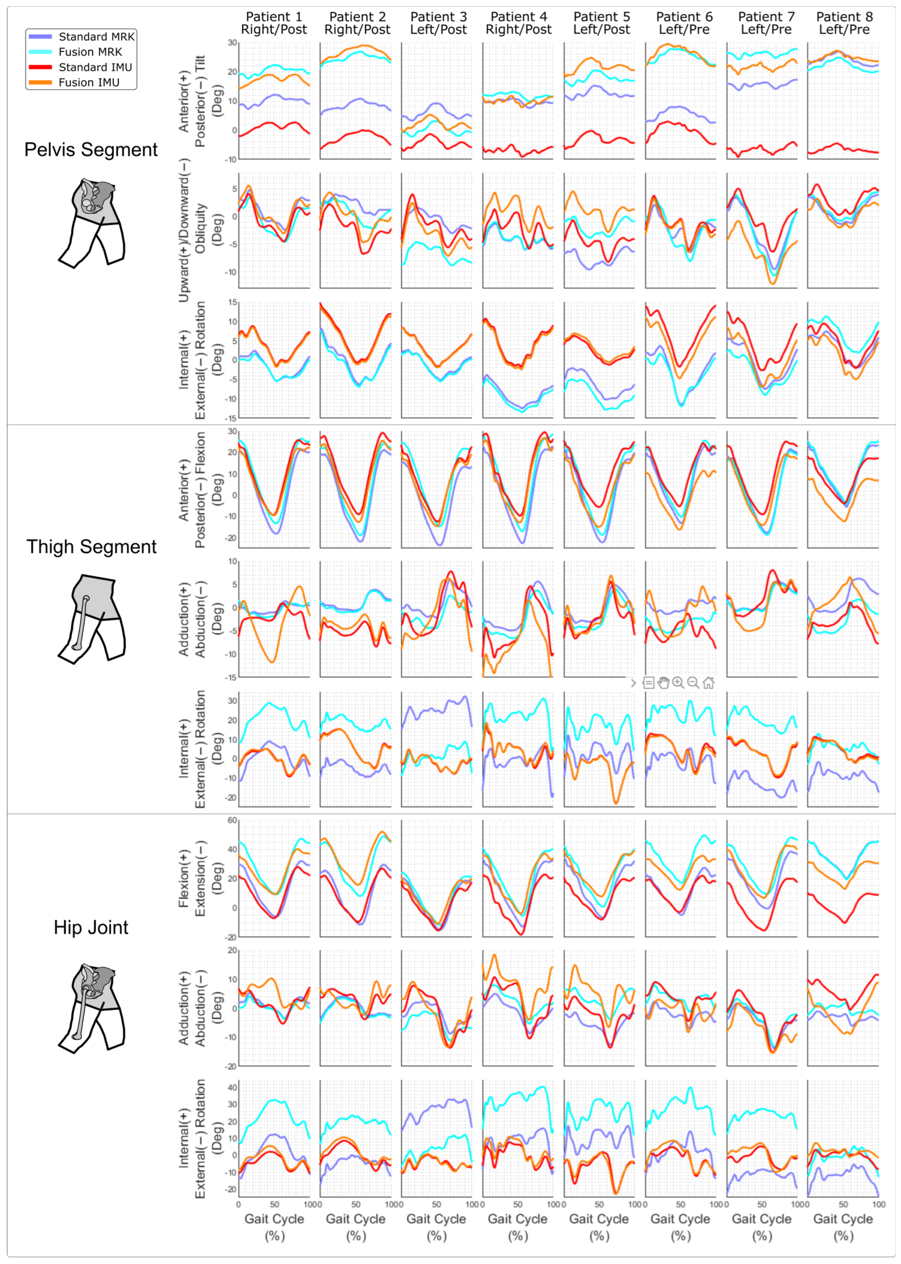
3. Results
4. Discussion
5. Conclusions
Supplementary Materials
Author Contributions
Funding
Institutional Review Board Statement
Informed Consent Statement
Data Availability Statement
Conflicts of Interest
References
- Wren, T.A.L.; Gorton, G.E.; Õunpuu, S.; Tucker, C.A. Efficacy of clinical gait analysis: A systematic review. Gait Posture 2011, 34, 149–153. [Google Scholar] [CrossRef] [PubMed]
- Baker, R.; Esquenazi, A.; Benedetti, M.G.; Desloovere, K. Gait analysis: Clinical facts. Eur. J. Phys. Rehabil. Med. 2016, 52, 560–574. [Google Scholar] [PubMed]
- World Health Organization. How to Use the ICF: A Practical Manual for Using the International Classification of Functioning, Disability and Health (ICF); World Health Organization: Geneva, Switzerland, 2013.
- Picerno, P. 25 years of lower limb joint kinematics by using inertial and magnetic sensors: A review of methodological approaches. Gait Posture 2017, 51, 239–246. [Google Scholar] [CrossRef] [PubMed]
- Ortega-Bastidas, P.; Gómez, B.; Aqueveque, P.; Luarte-Martínez, S.; Cano-de-la-Cuerda, R. Instrumented Timed Up and Go Test (iTUG)-More Than Assessing Time to Predict Falls: A Systematic Review. Sensors 2023, 23, 3426. [Google Scholar] [CrossRef] [PubMed]
- Nazarahari, M.; Rouhani, H. 40 years of sensor fusion for orientation tracking via magnetic and inertial measurement units: Methods, lessons learned, and future challenges. Inf. Fusion 2021, 68, 67–84. [Google Scholar] [CrossRef]
- Pacher, L.; Chatellier, C.; Vauzelle, R.; Fradet, L. Sensor-to-Segment Calibration Methodologies for Lower-Body Kinematic Analysis with Inertial Sensors: A Systematic Review. Sensors 2020, 20, 3322. [Google Scholar] [CrossRef] [PubMed]
- Carcreff, L.; Payen, G.; Grouvel, G.; Massé, F.; Armand, S. Three-Dimensional Lower-Limb Kinematics from Accelerometers and Gyroscopes with Simple and Minimal Functional Calibration Tasks: Validation on Asymptomatic Participants. Sensors 2022, 22, 5657. [Google Scholar] [CrossRef] [PubMed]
- Hull, M.L. Coordinate system requirements to determine motions of the tibiofemoral joint free from kinematic crosstalk errors. J. Biomech. 2020, 109, 109928. [Google Scholar] [CrossRef] [PubMed]
- Leineweber, M.J.; Gomez Orozco, M.D.; Andrysek, J. Evaluating the feasibility of two post-hoc correction techniques for mitigating posture-induced measurement errors associated with wearable motion capture. Med. Eng. Phys. 2019, 71, 38–44. [Google Scholar] [CrossRef] [PubMed]
- Gorton, G.E.; Hebert, D.A.; Gannotti, M.E. Assessment of the kinematic variability among 12 motion analysis laboratories. Gait Posture 2009, 29, 398–402. [Google Scholar] [CrossRef] [PubMed]
- Gasparutto, X.; Wegrzyk, J.; Rose-Dulcina, K.; Hannouche, D.; Armand, S. Can the fusion of motion capture and 3D medical imaging reduce the extrinsic variability due to marker misplacements? PLoS ONE 2020, 15, e0226648. [Google Scholar] [CrossRef] [PubMed]
- Leboeuf, F.; Baker, R.; Barré, A.; Reay, J.; Jones, R.; Sangeux, M. The conventional gait model, an open-source implementation that reproduces the past but prepares for the future. Gait Posture 2019, in press. [Google Scholar] [CrossRef] [PubMed]
- Barré, A.; Jolles, B.M.; Theumann, N.; Aminian, K. Soft tissue artifact distribution on lower limbs during treadmill gait: Influence of skin markers’ location on cluster design. J. Biomech. 2015, 48, 1965–1971. [Google Scholar] [CrossRef] [PubMed]
- Madgwick, S.O.H.; Harrison, A.J.L.; Vaidyanathan, R. Estimation of IMU and MARG orientation using a gradient descent algorithm. In Proceedings of the 2011 IEEE International Conference on Rehabilitation Robotics, Zurich, Switzerland, 29 June–1 July 2011; pp. 1–7. [Google Scholar]
- Gasparutto, X.; Besonhe, P.; DiGiovanni, P.L.; Armand, S.; Hannouche, D. Definition and reliability of 3D acetabular and global offset measurements from bi-plane X-rays. Sci. Rep. 2023, 13, 591. [Google Scholar] [CrossRef] [PubMed]
- Hara, R.; McGinley, J.; Briggs, C.; Baker, R.; Sangeux, M. Predicting the location of the hip joint centres, impact of age group and sex. Sci. Rep. 2016, 6, 37707. [Google Scholar] [CrossRef] [PubMed]
- Baker, R.; Leboeuf, F.; Reay, J.; Sangeux, M. The Conventional Gait Model-Success and Limitations. In Handbook of Human Motion; Müller, B., Wolf, S.I., Eds.; Springer International Publishing AG: Cham, Switzerland, 2017; pp. 1–19. [Google Scholar]
- Mariani, B.; Rouhani, H.; Crevoisier, X.; Aminian, K. Quantitative estimation of foot-flat and stance phase of gait using foot-worn inertial sensors. Gait Posture 2013, 37, 229–234. [Google Scholar] [CrossRef] [PubMed]
- Rivière, C.; Lazennec, J.Y.; Van Der Straeten, C.; Auvinet, E.; Cobb, J.; Muirhead-Allwood, S. The influence of spine-hip relations on total hip replacement: A systematic review. Orthop. Traumatol. Surg. Res. 2017, 103, 559–568. [Google Scholar] [CrossRef] [PubMed]
- Gasparutto, X.; Besonhe, P.; DiGiovanni, P.L.; Zingg, M.; Boudabbous, S.; Armand, S.; Hannouche, D. Reliability of the pelvis and femur anatomical landmarks and geometry with the EOS system before and after total hip arthroplasty. Sci. Rep. 2022, 12, 21420. [Google Scholar] [CrossRef] [PubMed]
- Camomilla, V.; Dumas, R.; Cappozzo, A. Human movement analysis: The soft tissue artefact issue. J. Biomech. 2017, 62, 1–4. [Google Scholar] [CrossRef] [PubMed]


| Dof | A—Conventional MRK vs. IMU | B—Conventional MRK vs. Fusion IMU | C—Fusion MRK vs. IMU | Kruskall–Wallis (p-Value) | Post-Hoc Wilcoxon | |
|---|---|---|---|---|---|---|
| Pelvis | Tilt | 13.3 [7.8] | 6.9 [8.2] | 2.8 [1.3] | 0.004 | A > C |
| Obliquity | 2.3 [0.8] | 3 [3] | 2.8 [1.8] | 0.833 | - | |
| Rotation | 6.5 [4] | 6.4 [4.4] | 7 [4.1] | 0.779 | - | |
| Thigh | Flexion | 8.6 [3.1] | 7.3 [1.8] | 5.5 [1.8] | 0.33 | - |
| Add-Abd | 6.1 [3] | 6.7 [1.7] | 7 [1] | 0.728 | - | |
| Rotation | 11.4 [5.1] | 11.4 [5.2] | 18.1 [8.7] | 0.545 | - | |
| Hip | Flex-Ext | 7.2 [7.1] | 10.8 [4.5] | 5.8 [2] | 0.181 | - |
| Add-Abd | 4.6 [2.6] | 5.5 [2.6] | 6 [1.5] | 0.493 | - | |
| Rotation | 11.1 [5.4] | 11.9 [6.7] | 24.7 [13.1] | 0.183 | - |
| Dof | A—Conventional MRK vs. IMU | B—Conventional MRK vs. Fusion IMU | C—Fusion MRK vs. IMU | Kruskall–Wallis (p-Value) | Post-Hoc Wilcoxon | |
|---|---|---|---|---|---|---|
| Pelvis | Tilt | 0.6 [0.2] | 0.7 [0.3] | 0.6 [0.3] | 0.968 | - |
| Obliquity | 0.8 [0.2] | 0.8 [0.2] | 0.8 [0.2] | 0.935 | - | |
| Rotation | 0.9 [0.1] | 0.8 [0.1] | 0.8 [0.1] | 0.636 | - | |
| Thigh | Flexion | 1 [0] | 1 [0] | 1 [0] | 0.968 | - |
| Add-Abd | −0.3 [0.5] | −0.6 [0.4] | −0.6 [0.4] | 0.761 | - | |
| Rotation | 0.4 [0.3] | 0.4 [0.3] | 0.4 [0.3] | 0.954 | - | |
| Hip | Flex-Ext | 1 [0] | 1 [0] | 1 [0] | 0.998 | - |
| Add-Abd | 0.8 [0.4] | 0.5 [0.6] | 0.5 [0.6] | 0.221 | - | |
| Rotation | 0.3 [0.2] | 0.3 [0.2] | 0.3 [0.2] | 0.086 | - |
| Dof | A—Conventional MRK vs. IMU | B—Conventional MRK vs. Fusion IMU | C—Fusion MRK vs. IMU | Kruskall–Wallis (p-Value) | Post-Hoc Wilcoxon | |
|---|---|---|---|---|---|---|
| Pelvis | Tilt | 1.3 [0.8] | 1.1 [0.8] | 0.9 [0.6] | 0.914 | - |
| Obliquity | 2 [2.1] | 2 [2] | 2.6 [1.7] | 0.998 | - | |
| Rotation | 2.1 [1.4] | 2.2 [1.3] | 2.4 [1.6] | 0.578 | - | |
| Thigh | Flexion | 5.4 [2.1] | 6.3 [2.8] | 6.5 [2.7] | 0.573 | - |
| Add-Abd | 4.7 [3.4] | 6.3 [3.3] | 6.1 [4.2] | 0.255 | - | |
| Rotation | 5 [3.3] | 4.5 [3.7] | 4.6 [3.6] | 0.968 | - | |
| Hip | Flex-Ext | 4.2 [2.3] | 5.3 [3.6] | 5.7 [3.3] | 0.566 | - |
| Add-Abd | 6.8 [3.8] | 6.8 [7.6] | 6.9 [7.6] | 0.846 | - | |
| Rotation | 8.2 [7.7] | 8.8 [8.7] | 9.2 [9.2] | 0.878 | - |
Disclaimer/Publisher’s Note: The statements, opinions and data contained in all publications are solely those of the individual author(s) and contributor(s) and not of MDPI and/or the editor(s). MDPI and/or the editor(s) disclaim responsibility for any injury to people or property resulting from any ideas, methods, instructions or products referred to in the content. |
© 2024 by the authors. Licensee MDPI, Basel, Switzerland. This article is an open access article distributed under the terms and conditions of the Creative Commons Attribution (CC BY) license (https://creativecommons.org/licenses/by/4.0/).
Share and Cite
Gasparutto, X.; Rose-Dulcina, K.; Grouvel, G.; DiGiovanni, P.; Carcreff, L.; Hannouche, D.; Armand, S. Sensor-to-Bone Calibration with the Fusion of IMU and Bi-Plane X-rays. Sensors 2024, 24, 419. https://doi.org/10.3390/s24020419
Gasparutto X, Rose-Dulcina K, Grouvel G, DiGiovanni P, Carcreff L, Hannouche D, Armand S. Sensor-to-Bone Calibration with the Fusion of IMU and Bi-Plane X-rays. Sensors. 2024; 24(2):419. https://doi.org/10.3390/s24020419
Chicago/Turabian StyleGasparutto, Xavier, Kevin Rose-Dulcina, Gautier Grouvel, Peter DiGiovanni, Lena Carcreff, Didier Hannouche, and Stéphane Armand. 2024. "Sensor-to-Bone Calibration with the Fusion of IMU and Bi-Plane X-rays" Sensors 24, no. 2: 419. https://doi.org/10.3390/s24020419
APA StyleGasparutto, X., Rose-Dulcina, K., Grouvel, G., DiGiovanni, P., Carcreff, L., Hannouche, D., & Armand, S. (2024). Sensor-to-Bone Calibration with the Fusion of IMU and Bi-Plane X-rays. Sensors, 24(2), 419. https://doi.org/10.3390/s24020419