
Resistive, Temperature-Independent Metal Oxide Gas Sensor for Detecting the Oxygen Stoichiometry (Air-Fuel Ratio) of Lean Engine Exhaust Gases

Abstract
1. Introduction
2. Fundamentals
3. Materials and Methods
4. Results and Discussion
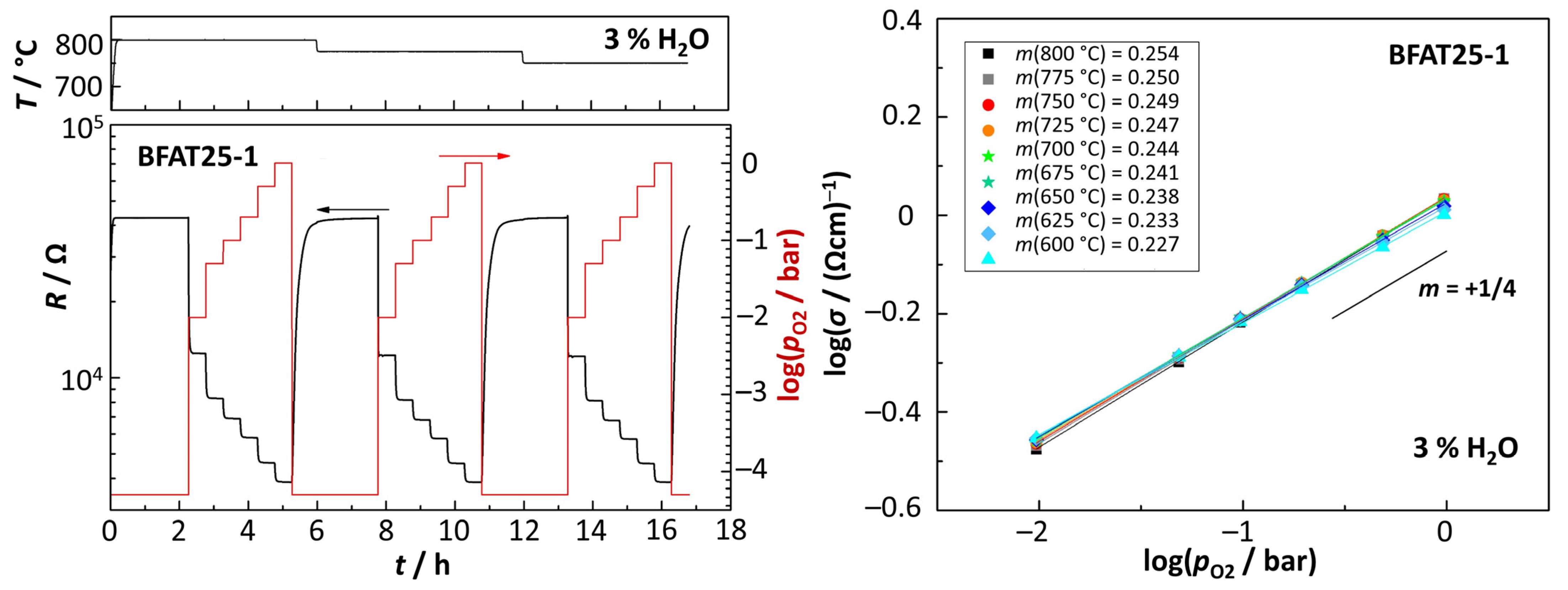
4.1. Analysis of Oxygen Sensitivity (BFAT25-1)
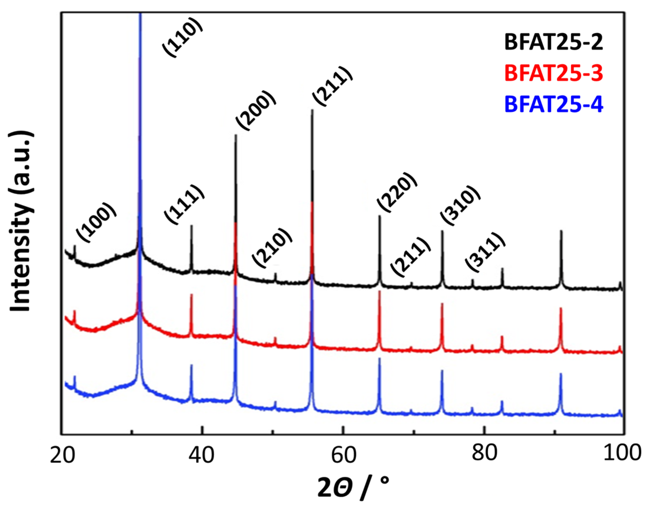
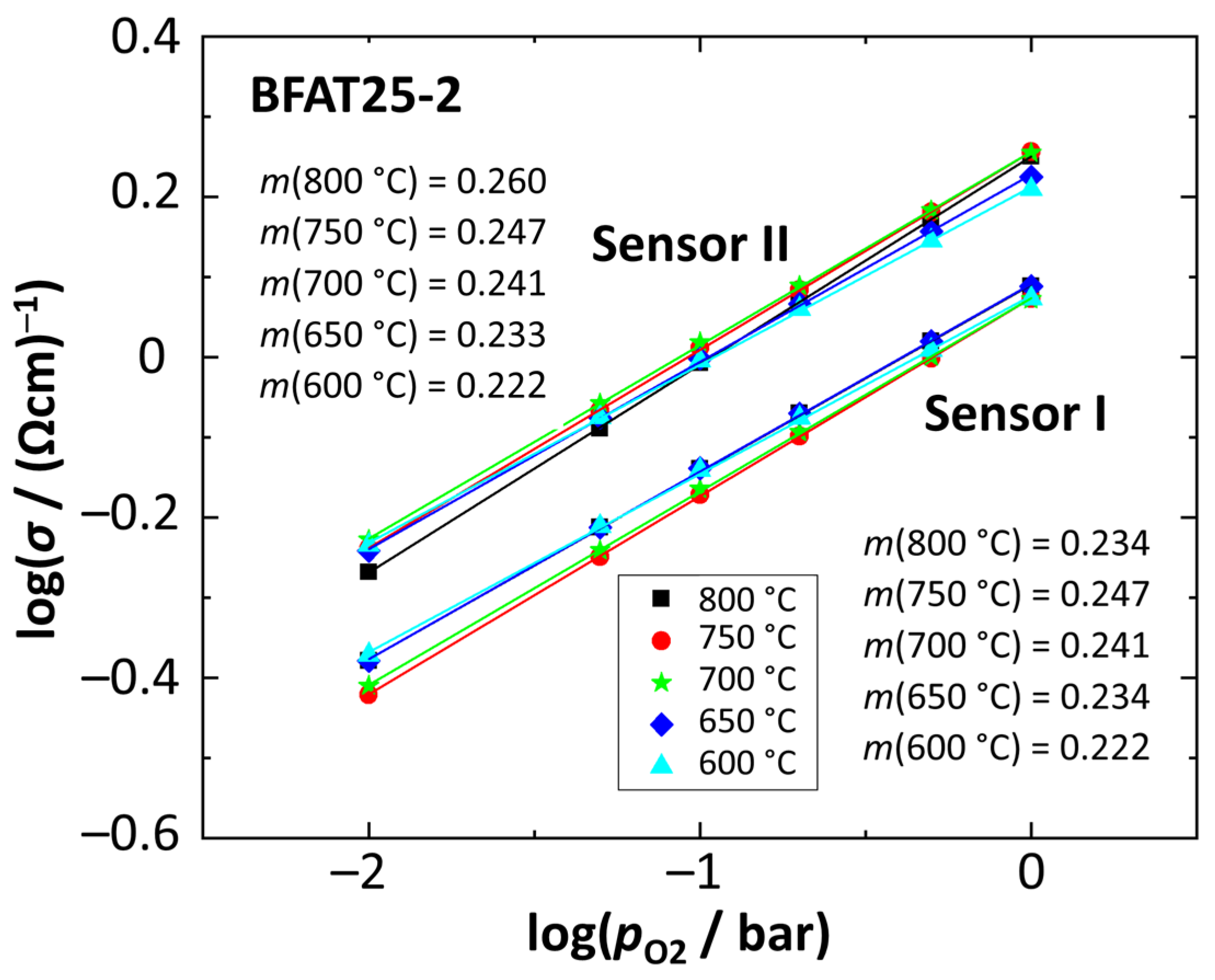
4.2. Reproducibility Studies on Oxygen Sensitivity (BFAT25-2,3,4)
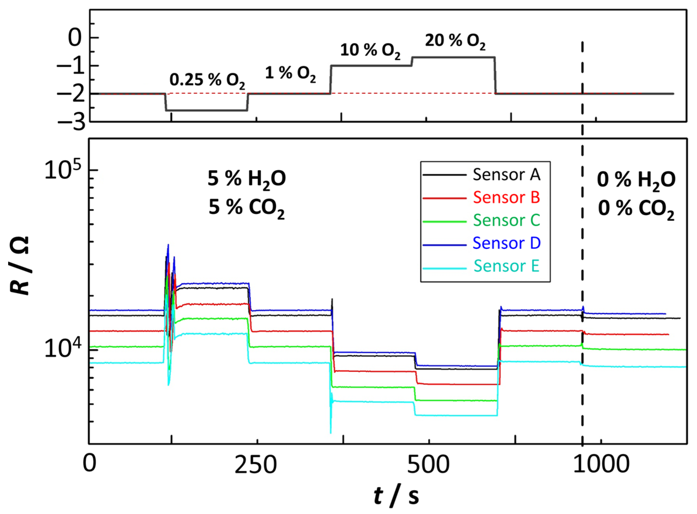
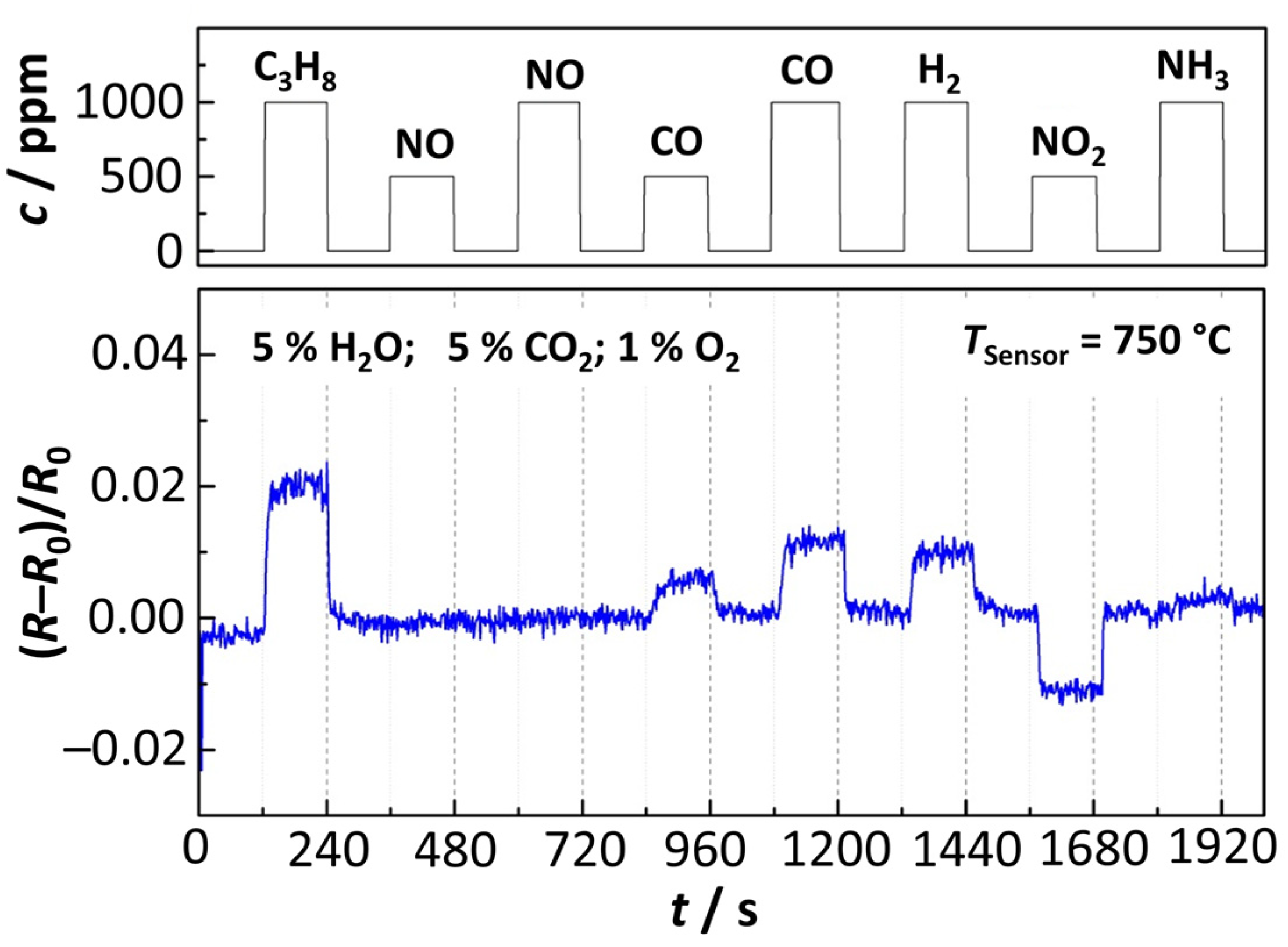
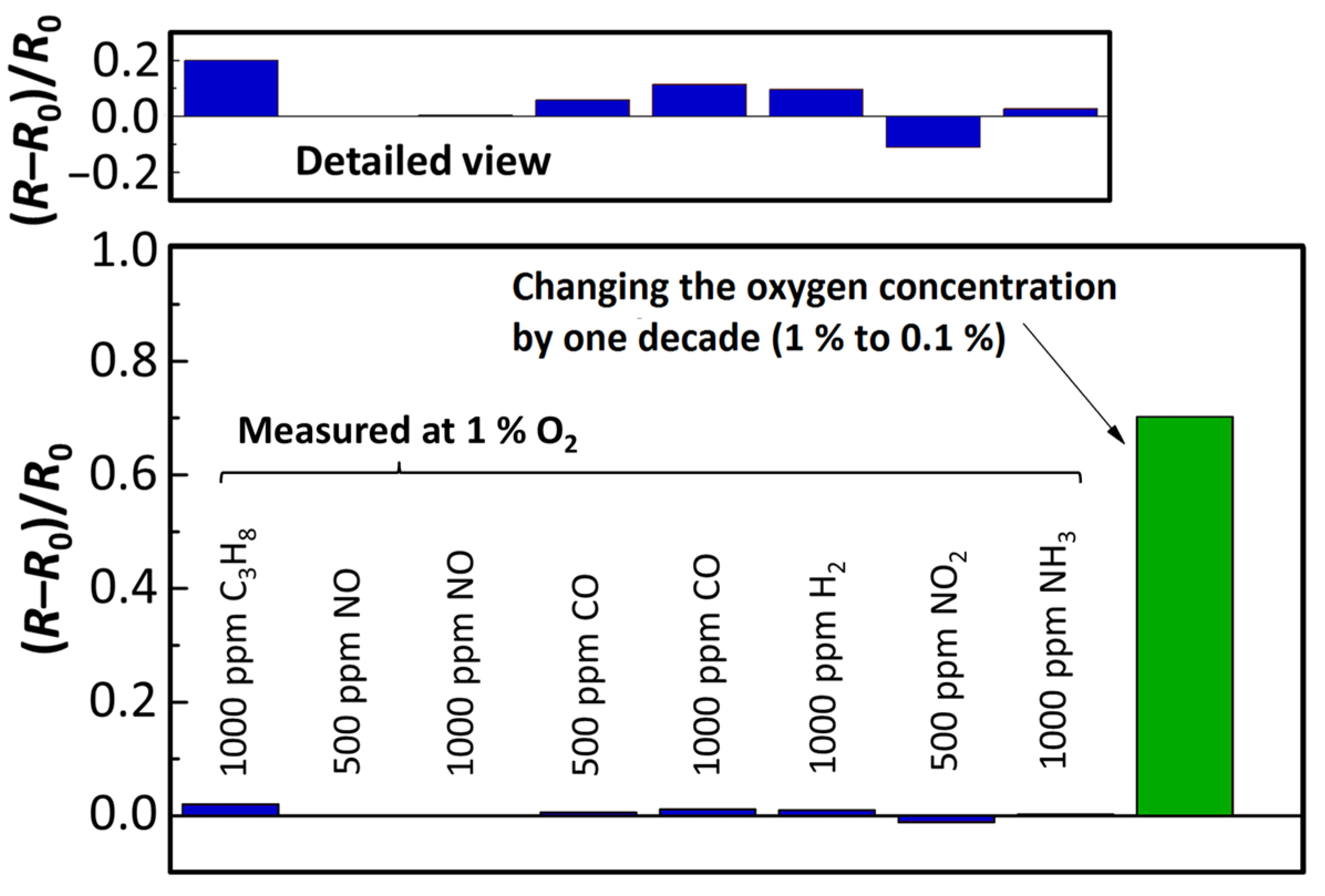
4.3. Studies on Selectivity of the Sensing Elements
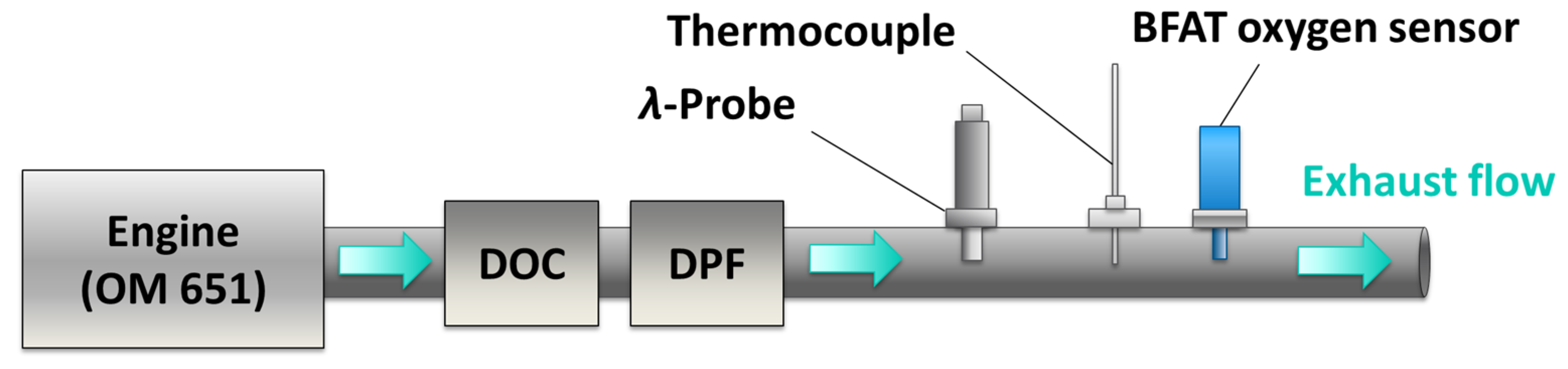
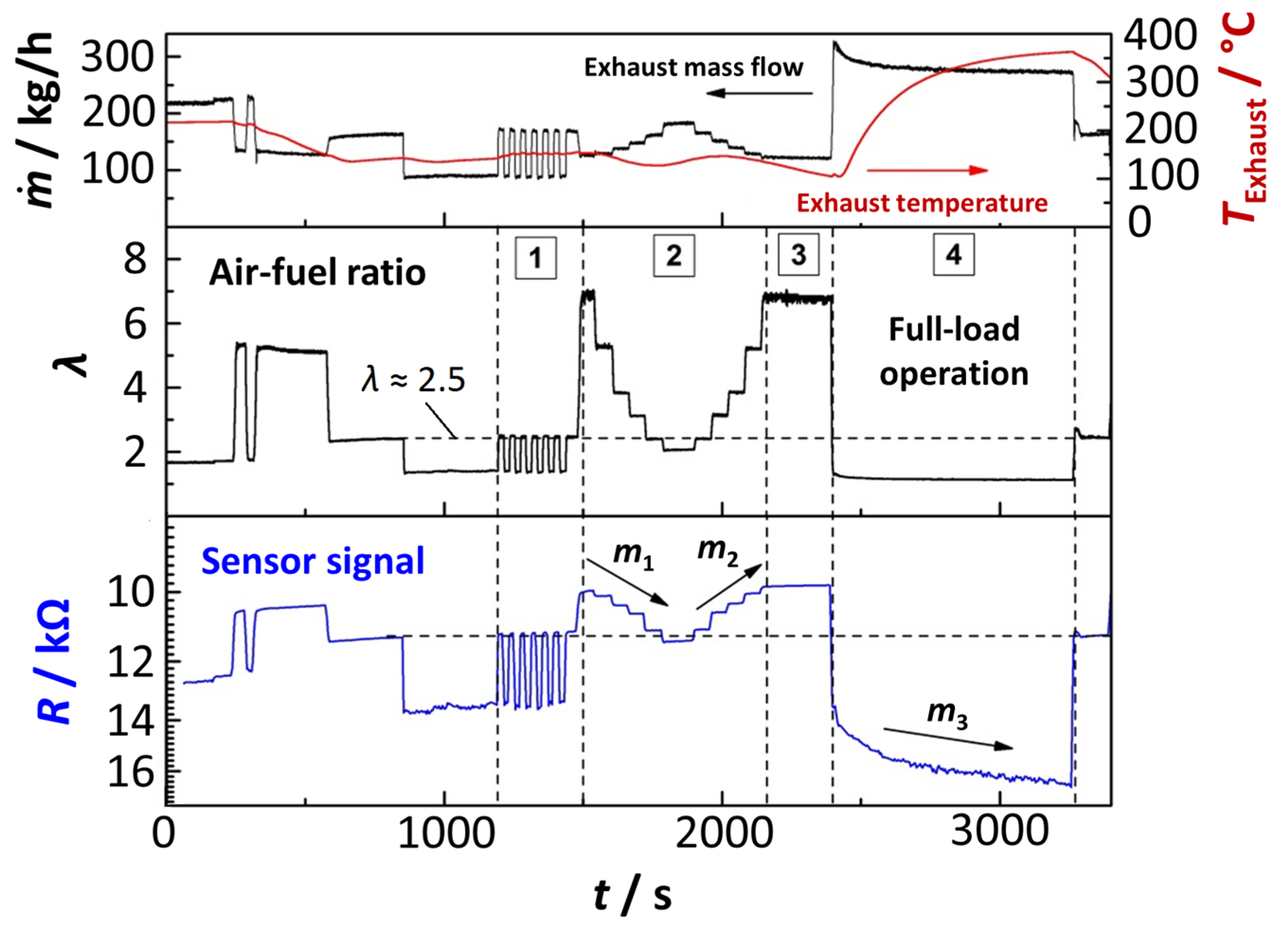
4.4. Tests in Real Exhaust Gas
5. Conclusions
Author Contributions
Funding
Data Availability Statement
Conflicts of Interest
References
- Deutschmann, O.; Grunwaldt, J.-D. Exhaust Gas Aftertreatment in Mobile Systems, Status, Challenges, and Perspectives. Chem. Ing. Tech. 2013, 85, 595–617. [Google Scholar] [CrossRef]
- Kreuzer, T.; Lox, E.S.; Lindner, D.; Leyrer, J. Advanced exhaust gas aftertreatment systems for gasoline and diesel fuelled vehicles. Catal. Today 1996, 29, 17–27. [Google Scholar] [CrossRef]
- Riegel, J. Exhaust gas sensors for automotive emission control. Solid State Ion. 2002, 152–153, 783–800. [Google Scholar] [CrossRef]
- Ramamoorthy, R.; Dutta, P.K.; Akbar, S.A. Oxygen sensors: Materials, methods, designs and applications. J. Mater. Sci. 2003, 38, 4271–4282. [Google Scholar] [CrossRef]
- Baunach, T.; Schänzlin, K.; Diehl, L. Sauberes Abgas durch Keramiksensoren. Phys. J. 2006, 5, 33–38. [Google Scholar]
- Ivers-Tiffée, E.; Härdtl, K.H.; Menesklou, W.; Riegel, J. Principles of solid state oxygen sensors for lean combustion gas control. Electrochim. Acta 2001, 47, 807–814. [Google Scholar] [CrossRef]
- Bektas, M.; Schönauer-Kamin, D.; Hagen, G.; Mergner, A.; Bojer, C.; Lippert, S.; Milius, W.; Breu, J.; Moos, R. BaFe1-xTaxO3-δ—A material for temperature independent resistive oxygen sensors. Sens. Actuators B Chem. 2014, 190, 208–213. [Google Scholar] [CrossRef]
- Bektas, M.; Stöcker, T.; Hagen, G.; Moos, R. On the defect chemistry of BaFe0.89Al0.01Ta0.1O3-δ, a material for temperature independent resistive and thermoelectric oxygen sensors. Solid State Ion. 2018, 316, 1–8. [Google Scholar] [CrossRef]
- Park, K.; Logothetis, E.M. Oxygen Sensing with Co1−xMgxO Ceramics. J. Electrochem. Soc. 1977, 124, 1443–1446. [Google Scholar] [CrossRef]
- Yu, C.; Shimizu, Y.; Arai, H. Investigation on a lean-burn oxygen sensor using perwovskite-type oxides. Chem. Lett. 1986, 15, 563–566. [Google Scholar] [CrossRef]
- Nozaki, H.; Tanaka, J.; Shibata, K. Oxygen-Sensitive Resistivity of La2CuO4 at High Temperatures. Jpn. J. Appl. Phys. 1987, 26, L1881. [Google Scholar] [CrossRef]
- Moos, R.; Rettig, F.; Hürland, A.; Plog, C. Temperature-independent resistive oxygen exhaust gas sensor for lean-burn engines in thick-film technology. Sens. Actuators B Chem. 2003, 93, 43–50. [Google Scholar] [CrossRef]
- Menesklou, W.; Schreiner, H.-J.; Härdtl, K.H.; Ivers-Tiffée, E. High temperature oxygen sensors based on doped SrTiO3. Sens. Actuators B Chem. 1999, 59, 184–189. [Google Scholar] [CrossRef]
- Rothschild, A.; Litzelman, S.J.; Tuller, H.L.; Menesklou, W.; Schneider, T.; Ivers-Tiffée, E. Temperature-independent resistive oxygen sensors based on SrTi1−xFexO3−δ solid solutions. Sens. Actuators B Chem. 2005, 108, 223–230. [Google Scholar] [CrossRef]
- Moos, R.; Izu, N.; Rettig, F.; Reiss, S.; Shin, W.; Matsubara, I. Resistive oxygen gas sensors for harsh environments. Sensors 2011, 11, 3439–3465. [Google Scholar] [CrossRef]
- Merkle, R.; Maier, J. How is oxygen incorporated into oxides? A comprehensive kinetic study of a simple solid-state reaction with SrTiO3 as a model material. Angew. Chem. Int. Ed. Engl. 2008, 47, 3874–3894. [Google Scholar] [CrossRef]
- Rettig, F.; Moos, R.; Plog, C. Poisoning of Temperature Independent Resistive Oxygen Sensors by Sulfur Dioxide. J. Electroceram. 2004, 13, 733–738. [Google Scholar] [CrossRef]
- Moseley, P.T.; Williams, D.E. Gas sensors based on oxides of early transition metals. Polyhedron 1989, 8, 1615–1618. [Google Scholar] [CrossRef]
- Moseley, P.T. Solid state gas sensors. J. Mater. Chem. 1997, 8, 223–237. [Google Scholar] [CrossRef]
- Gründler, P. Chemical Sensors: An Introduction for Scientists and Engineers; Springer: Berlin/Heidelberg, Germany, 2007; ISBN 978-3-540-45742-8. [Google Scholar] [CrossRef]
- Bektas, M.; Hanft, D.; Schönauer-Kamin, D.; Stöcker, T.; Hagen, G.; Moos, R. Aerosol-deposited BaFe0.7Ta0.3O3-δ for nitrogen monoxide and temperature-independent oxygen sensing. J. Sens. Sens. Syst. 2014, 3, 223–229. [Google Scholar] [CrossRef]
- Bektas, M.; Stöcker, T.; Mergner, A.; Hagen, G.; Moos, R. Combined resistive and thermoelectric oxygen sensor with almost temperature-independent characteristics. J. Sens. Sens. Syst. 2018, 7, 289–297. [Google Scholar] [CrossRef]
- Schubert, M.; Hanft, D.; Nazarenus, T.; Exner, J.; Schubert, M.; Nieke, P.; Glosse, P.; Leupold, N.; Kita, J.; Moos, R. Powder aerosol deposition method—Novel applications in the field of sensing and energy technology. Funct. Mater. Lett. 2019, 12, 1930005. [Google Scholar] [CrossRef]
- Exner, J.; Nazarenus, T.; Hanft, D.; Kita, J.; Moos, R. What Happens during Thermal Post-Treatment of Powder Aerosol Deposited Functional Ceramic Films? Explanations Based on an Experiment-Enhanced Literature Survey. Adv. Mater. 2020, 32, e1908104. [Google Scholar] [CrossRef]
- Brettschneider, J. Calculation of the air ratio lambda of air fuel mixtures and its effect on measurement errors. Bosch Tech. Ber. 1979, 6, 177–181. [Google Scholar]
- Brettschneider, J. Extension of the Equation for Calculation of the Air-Fuel Equivalence Ratio. SAE Tech. Pap. 1997, 972989. [Google Scholar] [CrossRef]


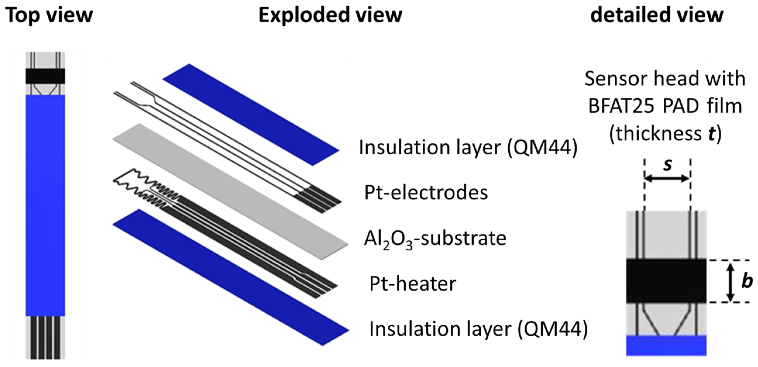
| Batch | Sensor-# | Thickness t/µm | Width b/µm | Distance s/µm |
|---|---|---|---|---|
| BFAT25-2 | I | 3.1 | 2450 | 3508 |
| II | 2.3 | 2443 | 3499 | |
| BFAT25-3 | I | 4.0 | 2445 | 3513 |
| II | 2.6 | 2447 | 3507 | |
| BFAT25-4 | I | 4.4 | 2432 | 3534 |
| II | 5.1 | 2443 | 3511 | |
| Mean | 3.6 | 2450 | 3512 | |
| Std.-Deviation | 1.0 | 14.22 | 10.73 |
| Batch | Sensor-# | m (800 °C) | m (750 °C) | m (700 °C) | m (650 °C) | m (600 °C) |
|---|---|---|---|---|---|---|
| BFAT25-2 | I | 0.234 | 0.247 | 0.241 | 0.234 | 0.222 |
| II | 0.260 | 0.247 | 0.241 | 0.233 | 0.222 | |
| BFAT25-3 | I | 0.260 | 0.246 | 0.239 | 0.231 | 0.218 |
| II | 0.259 | 0.246 | 0.240 | 0.232 | 0.218 | |
| BFAT25-4 | I | 0.262 | 0.249 | 0.244 | 0.236 | 0.225 |
| II | 0.262 | 0.249 | 0.243 | 0.235 | 0.224 | |
| Mean | 0.261 | 0.248 | 0.242 | 0.234 | 0.222 | |
| Std.-Deviation | 0.0244 | 0.0013 | 0.0017 | 0.0017 | 0.0027 |
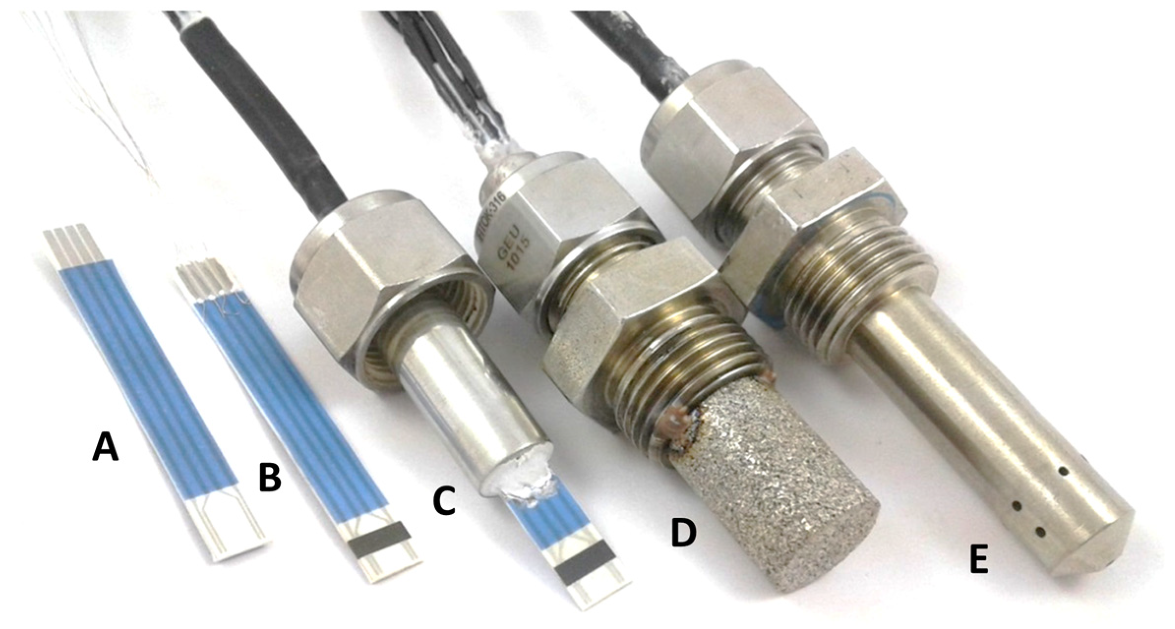
| Signal | Sensor A (BFAT25-1) | Sensor B (BFAT25-2) | Sensor C (BFAT25-2) | Sensor D (BFAT25-3) | Sensor E (BFAT25-4) |
|---|---|---|---|---|---|
| R/kΩ | 15.041 | 12.222 | 10.121 | 15.954 | 8.105 |
| R0 (H2O and CO2)/kΩ | 15.608 | 12.753 | 10.555 | 16.685 | 8.604 |
| R/R0 | 0.964 | 0.958 | 0.959 | 0.956 | 0.942 |
Disclaimer/Publisher’s Note: The statements, opinions and data contained in all publications are solely those of the individual author(s) and contributor(s) and not of MDPI and/or the editor(s). MDPI and/or the editor(s) disclaim responsibility for any injury to people or property resulting from any ideas, methods, instructions or products referred to in the content. |
© 2023 by the authors. Licensee MDPI, Basel, Switzerland. This article is an open access article distributed under the terms and conditions of the Creative Commons Attribution (CC BY) license (https://creativecommons.org/licenses/by/4.0/).
Share and Cite
Steiner, C.; Püls, S.; Bektas, M.; Müller, A.; Hagen, G.; Moos, R. Resistive, Temperature-Independent Metal Oxide Gas Sensor for Detecting the Oxygen Stoichiometry (Air-Fuel Ratio) of Lean Engine Exhaust Gases. Sensors 2023, 23, 3914. https://doi.org/10.3390/s23083914
Steiner C, Püls S, Bektas M, Müller A, Hagen G, Moos R. Resistive, Temperature-Independent Metal Oxide Gas Sensor for Detecting the Oxygen Stoichiometry (Air-Fuel Ratio) of Lean Engine Exhaust Gases. Sensors. 2023; 23(8):3914. https://doi.org/10.3390/s23083914
Chicago/Turabian StyleSteiner, Carsten, Simon Püls, Murat Bektas, Andreas Müller, Gunter Hagen, and Ralf Moos. 2023. "Resistive, Temperature-Independent Metal Oxide Gas Sensor for Detecting the Oxygen Stoichiometry (Air-Fuel Ratio) of Lean Engine Exhaust Gases" Sensors 23, no. 8: 3914. https://doi.org/10.3390/s23083914
APA StyleSteiner, C., Püls, S., Bektas, M., Müller, A., Hagen, G., & Moos, R. (2023). Resistive, Temperature-Independent Metal Oxide Gas Sensor for Detecting the Oxygen Stoichiometry (Air-Fuel Ratio) of Lean Engine Exhaust Gases. Sensors, 23(8), 3914. https://doi.org/10.3390/s23083914