
A Comparative Study on the Effects of Spray Coating Methods and Substrates on Polyurethane/Carbon Nanofiber Sensors

 ,
, 
Abstract
1. Introduction
2. Experimental Section
2.1. Materials
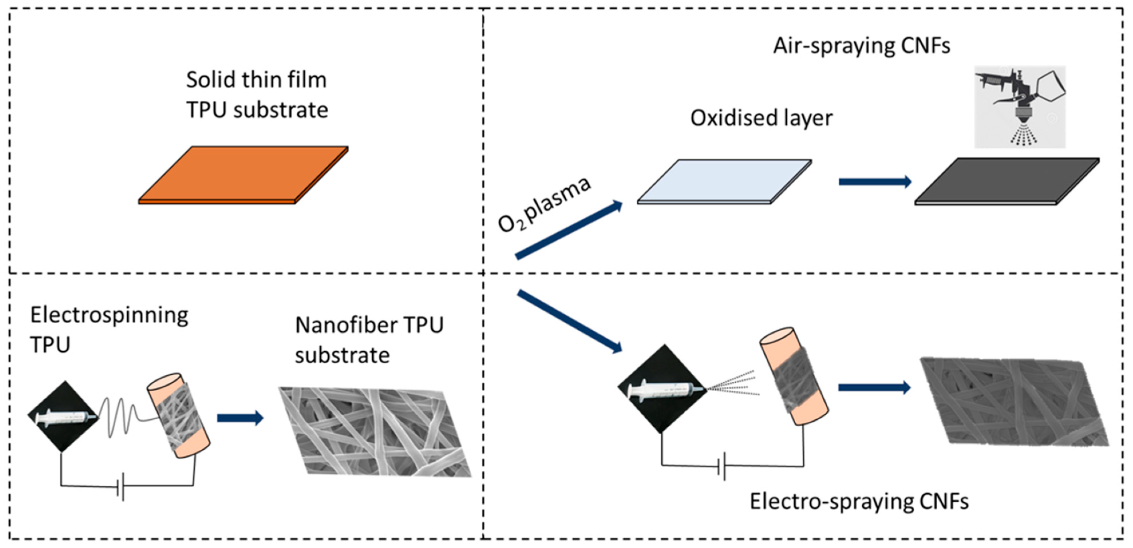
2.2. Fabrication of TPU/CNFs Strain Sensors
2.3. Characterisation
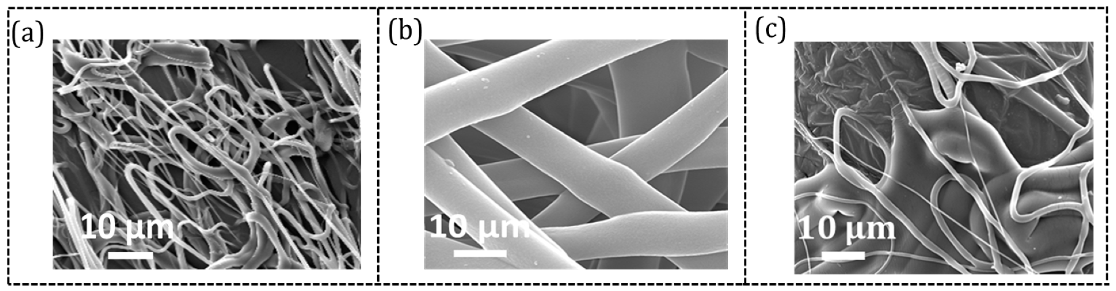
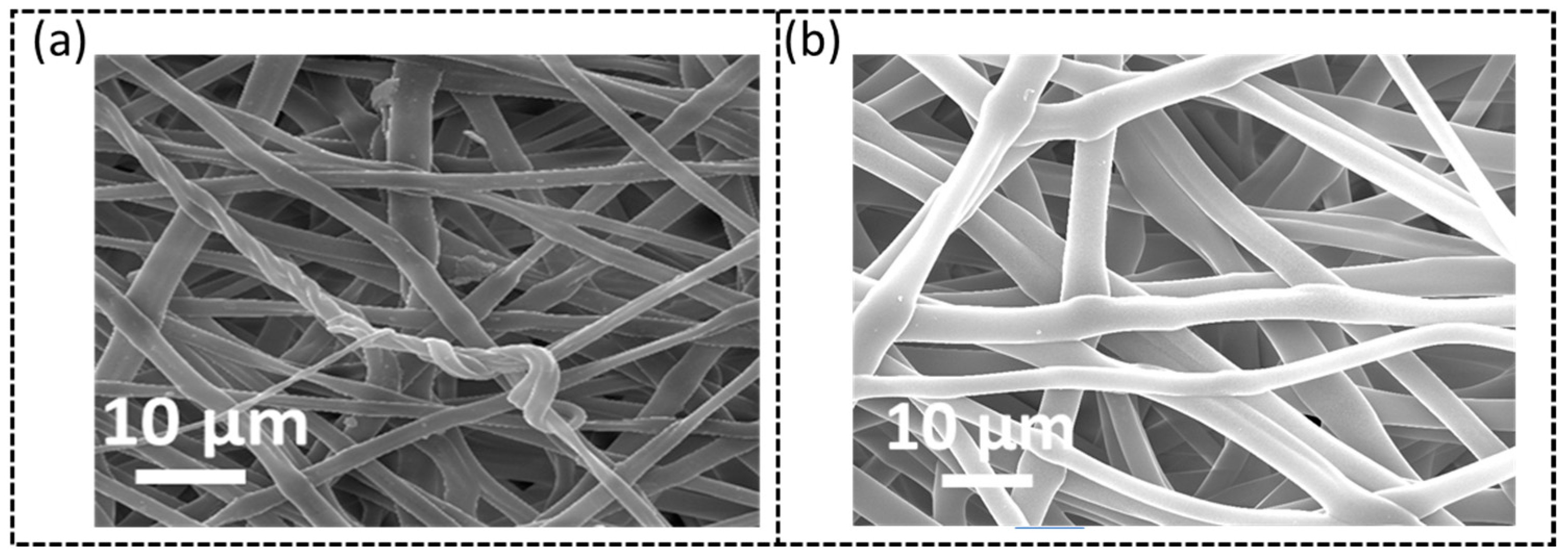
2.3.1. Morphology
2.3.2. Piezoresistivity Measurements
3. Results and Discussion
3.1. Effects of Electrospinning Parameters on Nanofiber Production
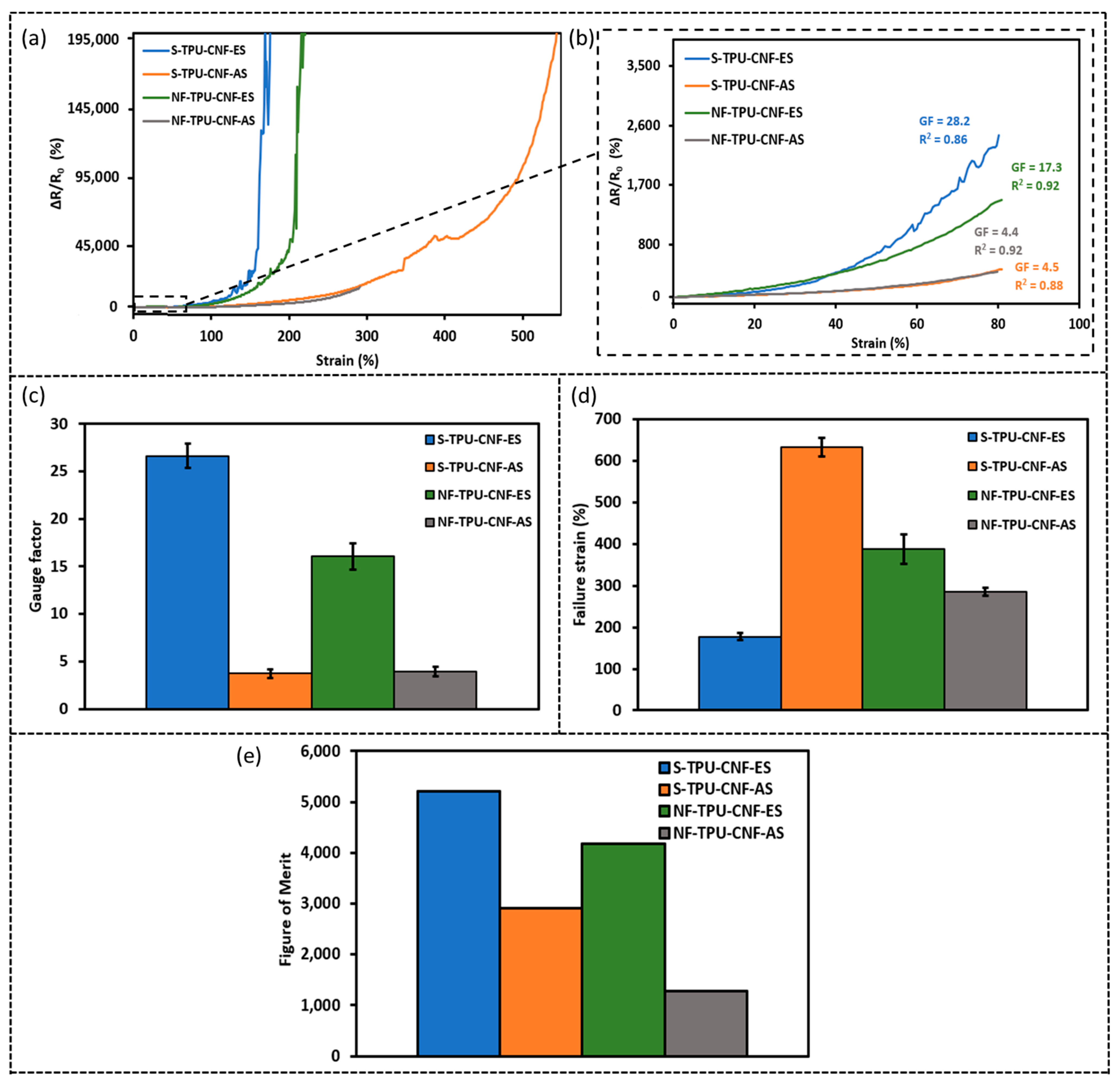
3.2. Piezoresistivity of the TPU/CNFs Sensors
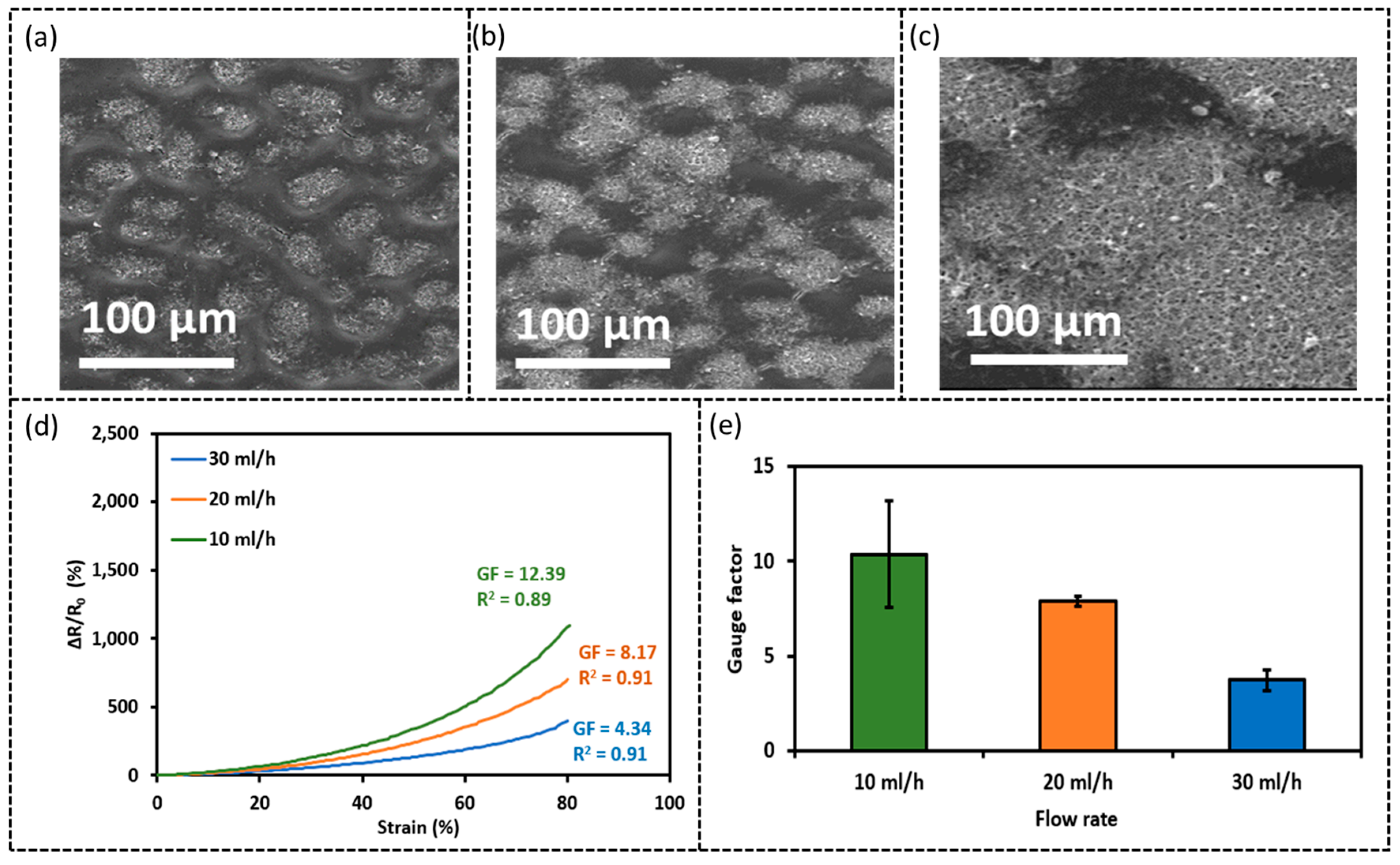
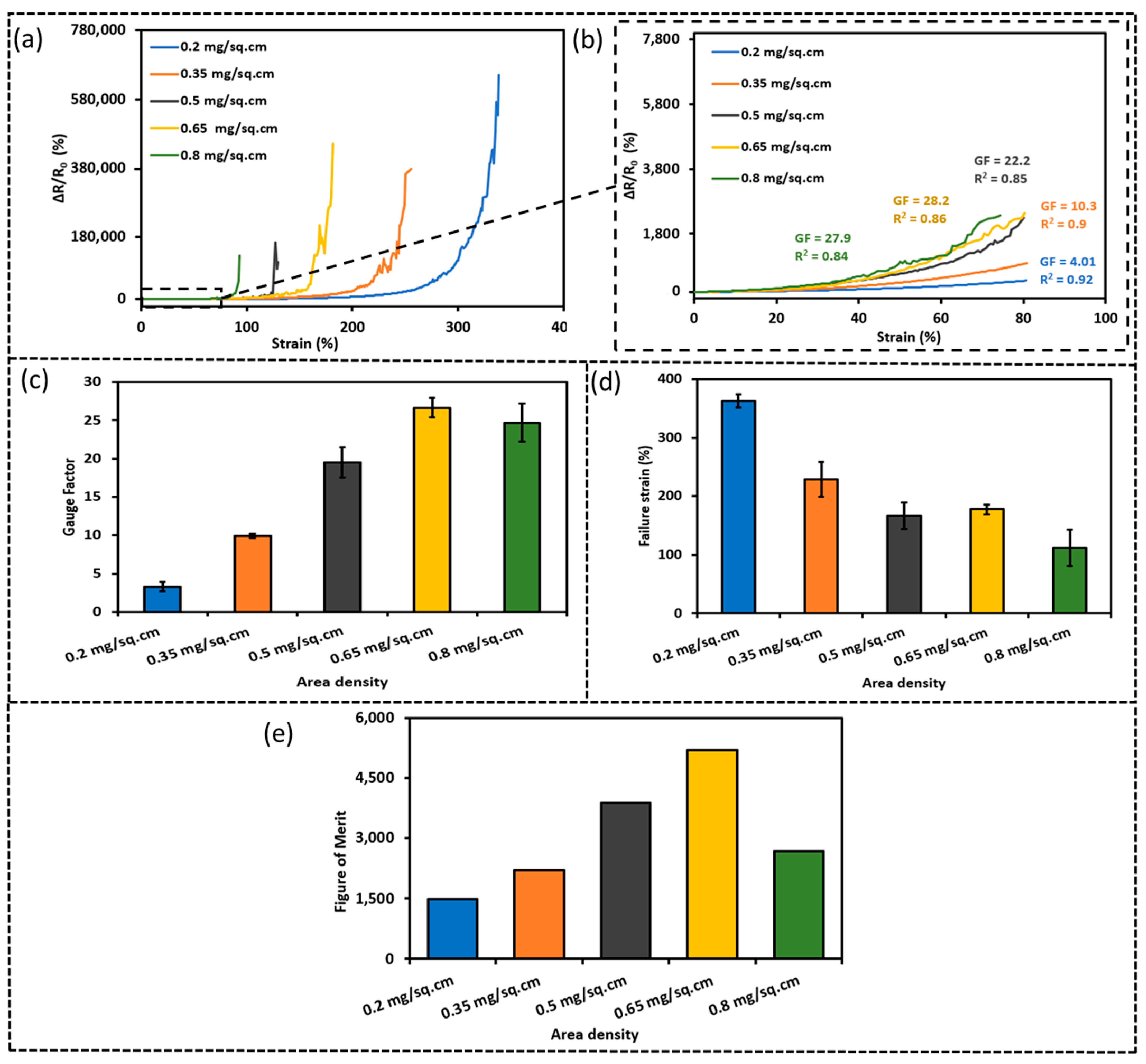
3.3. Influences of Electro-Spray Parameters and CNF Area Density
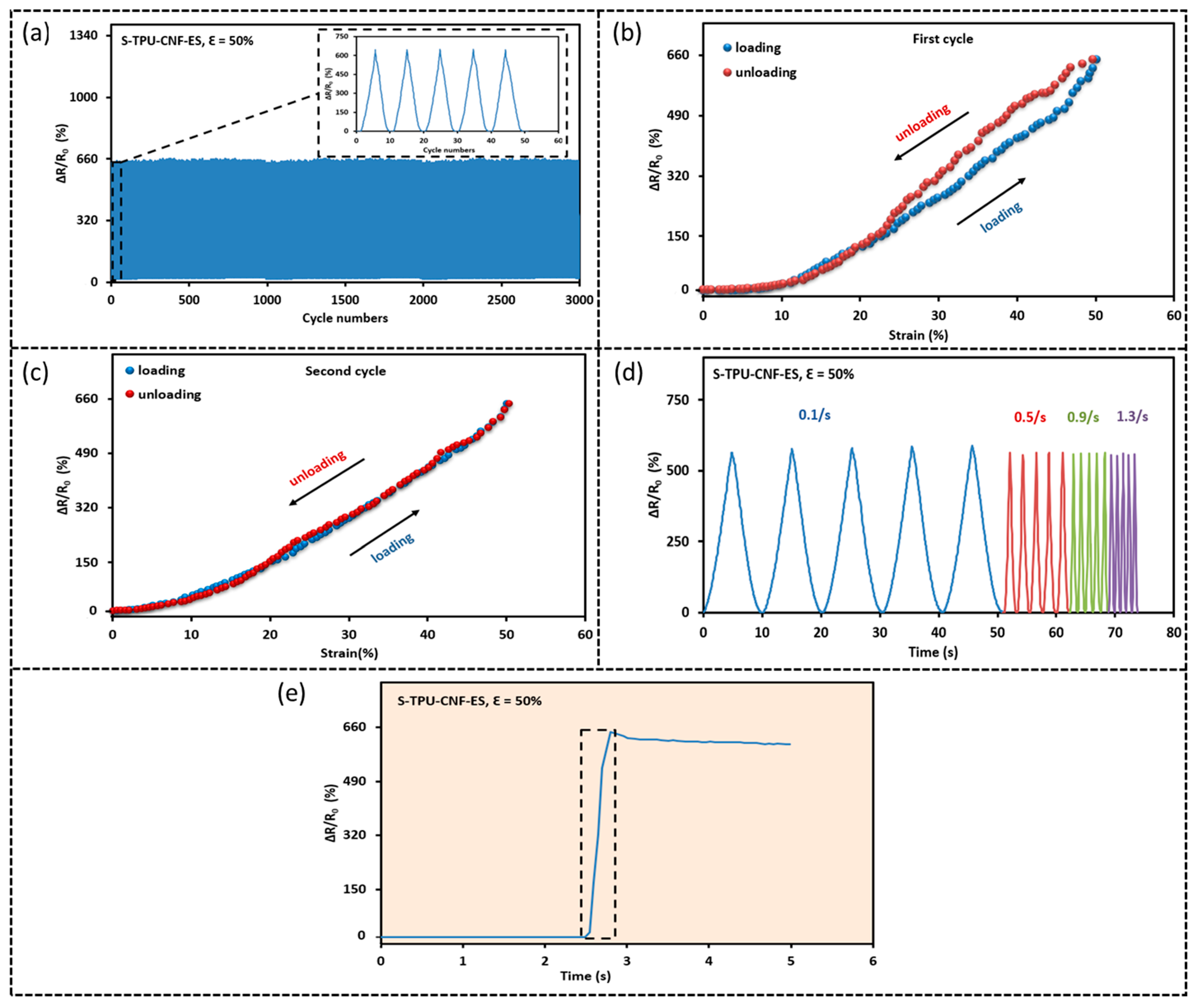
3.4. Durability, Response Time, and Responses to Different Strain Rates
3.5. Piezoresistivity Mechanism
3.6. Application Demonstration
4. Conclusions
Author Contributions
Funding
Institutional Review Board Statement
Informed Consent Statement
Data Availability Statement
Acknowledgments
Conflicts of Interest
References
- Wang, Y.; Gong, S.; Wang, S.J.; Yang, X.; Ling, Y.; Yap, L.W.; Dong, D.; Simon, G.P.; Cheng, W. Standing enokitake-like nanowire films for highly stretchable elastronics. ACS Nano 2018, 12, 9742–9749. [Google Scholar] [CrossRef] [PubMed]
- Jason, N.N.; Ho, M.D.; Cheng, W. Resistive electronic skin. J. Mater. Chem. C 2017, 5, 5845–5866. [Google Scholar] [CrossRef]
- Han, S.; Wan, Q.; Zhou, K.; Yan, A.; Lin, Z.; Shu, B.; Liu, C. Sensitive, Stretchable, and Breathable Pressure Sensors Based on Medical Gauze Integrated with Silver Nanowires and Elastomers. ACS Appl. Nano Mater. 2021, 4, 8273–8281. [Google Scholar] [CrossRef]
- Vu, C.C.; Kim, J. Waterproof, thin, high-performance pressure sensors-hand drawing for underwater wearable applications. Sci. Technol. Adv. Mater. 2021, 22, 718–728. [Google Scholar] [CrossRef]
- Liang, X.; Zhu, M.; Li, H.; Dou, J.; Jian, M.; Xia, K.; Li, S.; Zhang, Y. Hydrophilic, breathable, and washable graphene decorated textile assisted by silk sericin for integrated multimodal smart wearables. Adv. Funct. Mater. 2022, 32, 2200162. [Google Scholar] [CrossRef]
- Song, Z.; Li, W.; Bao, Y.; Wang, W.; Liu, Z.; Han, F.; Han, D.; Niu, L. Bioinspired microstructured pressure sensor based on a janus graphene film for monitoring vital signs and cardiovascular assessment. Adv. Electron. Mater. 2018, 4, 1800252. [Google Scholar] [CrossRef]
- Yu, Y.; Peng, S.; Sha, Z.; Cheng, T.X.; Wu, S.; Wang, C.H. High-precision, stretchable kirigami-capacitive sensor with ultra-low cross-sensitivity for body temperature monitoring. J. Mater. Chem. A 2021, 9, 24874–24886. [Google Scholar] [CrossRef]
- Huang, J.; Li, D.; Zhao, M.; Mensah, A.; Lv, P.; Tian, X.; Huang, F.; Ke, H.; Wei, Q. Highly Sensitive and Stretchable CNT-Bridged AgNP Strain Sensor Based on TPU Electrospun Membrane for Human Motion Detection. Adv. Electron. Mater. 2019, 5, 1900241. [Google Scholar] [CrossRef]
- Li, S.; Fu, Q.; Pan, C. A multi-functional wearable sensor based on carbon nanomaterials reinforced TPU fiber with high sensitivity. J. Alloys Compd. 2022, 927, 167041. [Google Scholar] [CrossRef]
- Li, R.; Wei, X.; Xu, J.; Chen, J.; Li, B.; Wu, Z.; Wang, Z.L. Smart wearable sensors based on triboelectric nanogenerator for personal healthcare monitoring. Micromachines 2021, 12, 352. [Google Scholar] [CrossRef]
- Wu, S.; Peng, S.; Yu, Y.; Wang, C.H. Strategies for designing stretchable strain sensors and conductors. Adv. Mater. Technol. 2020, 5, 1900908. [Google Scholar] [CrossRef]
- Zhang, X.; Xiang, D.; Zhu, W.; Zheng, Y.; Harkin-Jones, E.; Wang, P.; Zhao, C.; Li, H.; Wang, B.; Li, Y. Flexible and high-performance piezoresistive strain sensors based on carbon nanoparticles@ polyurethane sponges. Compos. Sci. Technol. 2020, 200, 108437. [Google Scholar] [CrossRef]
- Yan, J.; Ma, Y.; Li, X.; Zhang, C.; Cao, M.; Chen, W.; Luo, S.; Zhu, M.; Gao, Y. Flexible and high-sensitivity piezoresistive sensor based on MXene composite with wrinkle structure. Ceram. Int. 2020, 46, 23592–23598. [Google Scholar] [CrossRef]
- Yi, Y.; Wang, B.; Liu, X.; Li, C. Flexible piezoresistive strain sensor based on CNTs–polymer composites: A brief review. Carbon Lett. 2022, 32, 713–726. [Google Scholar] [CrossRef]
- Ding, Y.; Yang, J.; Tolle, C.R.; Zhu, Z. A highly stretchable strain sensor based on electrospun carbon nanofibers for human motion monitoring. RSC Adv. 2016, 6, 79114–79120. [Google Scholar] [CrossRef]
- Chowdhury, S.A.; Saha, M.C.; Patterson, S.; Robison, T.; Liu, Y. Highly conductive polydimethylsiloxane/carbon nanofiber composites for flexible sensor applications. Adv. Mater. Technol. 2019, 4, 1800398. [Google Scholar] [CrossRef]
- Ali, M.M.; Maddipatla, D.; Narakathu, B.B.; Chlaihawi, A.A.; Emamian, S.; Janabi, F.; Bazuin, B.J.; Atashbar, M.Z. Printed strain sensor based on silver nanowire/silver flake composite on flexible and stretchable TPU substrate. Sens. Actuators A Phys. 2018, 274, 109–115. [Google Scholar]
- Zhao, Z.; Li, Q.; Dong, Y.; Gong, J.; Li, Z.; Qiao, X.; Zhang, J. A wearable sensor based on gold nanowires/textile and its integrated smart glove for motion monitoring and gesture expression. Energy Technol. 2021, 9, 2100166. [Google Scholar] [CrossRef]
- Bi, L.; Yang, Z.; Chen, L.; Wu, Z.; Ye, C. Compressible AgNWs/Ti3C2Tx MXene aerogel-based highly sensitive piezoresistive pressure sensor as versatile electronic skins. J. Mater. Chem. A 2020, 8, 20030–20036. [Google Scholar] [CrossRef]
- Gong, S.; Cheng, W. One-dimensional nanomaterials for soft electronics. Adv. Electron. Mater. 2017, 3, 1600314. [Google Scholar] [CrossRef]
- Guo, L.; Wan, K.; Liu, B.; Wang, Y.; Wei, G. Recent advance in the fabrication of carbon nanofiber-based composite materials for wearable devices. Nanotechnology 2021, 32, 442001. [Google Scholar] [CrossRef]
- Fu, R.; Zhao, X.; Zhang, X.; Su, Z. Design strategies and applications of wearable piezoresistive strain sensors with dimensionality-based conductive network structures. Chem. Eng. J. 2022, 454, 140467. [Google Scholar] [CrossRef]
- Wang, Y.; Guo, L.; Qi, P.; Liu, X.; Wei, G. Synthesis of three-dimensional graphene-based hybrid materials for water purification: A review. Nanomaterials 2019, 9, 1123. [Google Scholar] [CrossRef] [PubMed]
- Wu, S.; Zhang, J.; Ladani, R.B.; Ravindran, A.R.; Mouritz, A.P.; Kinloch, A.J.; Wang, C.H. Novel electrically conductive porous PDMS/carbon nanofiber composites for deformable strain sensors and conductors. ACS Appl. Mater. Interfaces 2017, 9, 14207–14215. [Google Scholar] [CrossRef]
- Peng, S.; Wu, S.; Yu, Y.; Blanloeuil, P.; Wang, C.H. Nano-toughening of transparent wearable sensors with high sensitivity and a wide linear sensing range. J. Mater. Chem. A 2020, 8, 20531–20542. [Google Scholar] [CrossRef]
- Peng, S.; Wu, S.; Yu, Y.; Sha, Z.; Li, G.; Hoang, T.T.; Thai, M.T.; Do, T.N.; Chu, D.; Wang, C.H. Carbon nanofiber-reinforced strain sensors with high breathability and anisotropic sensitivity. J. Mater. Chem. A 2021, 9, 26788–26799. [Google Scholar] [CrossRef]
- Lee, J.-H.; Chen, H.; Kim, E.; Zhang, H.; Wu, K.; Zhang, H.; Shen, X.; Zheng, Q.; Yang, J.; Jeon, S. Flexible temperature sensors made of aligned electrospun carbon nanofiber films with outstanding sensitivity and selectivity towards temperature. Mater. Horiz. 2021, 8, 1488–1498. [Google Scholar] [CrossRef] [PubMed]
- Lee, J.H.; Kim, J.; Liu, D.; Guo, F.; Shen, X.; Zheng, Q.; Jeon, S.; Kim, J.K. Highly aligned, anisotropic carbon nanofiber films for multidirectional strain sensors with exceptional selectivity. Adv. Funct. Mater. 2019, 29, 1901623. [Google Scholar] [CrossRef]
- Xiao, J.; Xiong, Y.; Chen, J.; Zhao, S.; Chen, S.; Xu, B.; Sheng, B. Ultrasensitive and highly stretchable fibers with dual conductive microstructural sheaths for human motion and micro vibration sensing. Nanoscale 2022, 14, 1962–1970. [Google Scholar] [CrossRef]
- Lu, L.; Wei, X.; Zhang, Y.; Zheng, G.; Dai, K.; Liu, C.; Shen, C. A flexible and self-formed sandwich structure strain sensor based on AgNW decorated electrospun fibrous mats with excellent sensing capability and good oxidation inhibition properties. J. Mater. Chem. C 2017, 5, 7035–7042. [Google Scholar] [CrossRef]
- Zhang, Z.; Weng, L.; Guo, K.; Guan, L.; Wang, X.; Wu, Z. Durable and highly sensitive flexible sensors for wearable electronic devices with PDMS-MXene/TPU composite films. Ceram. Int. 2022, 48, 4977–4985. [Google Scholar] [CrossRef]
- Wang, Y.; Wang, J.; Cao, S.; Kong, D. A stretchable and breathable form of epidermal device based on elastomeric nanofibre textiles and silver nanowires. J. Mater. Chem. C 2019, 7, 9748–9755. [Google Scholar] [CrossRef]
- Fang, F.; Wang, H.; Wang, H.; Gu, X.; Zeng, J.; Wang, Z.; Chen, X.; Chen, X.; Chen, M. Stretchable MXene/thermoplastic polyurethanes based strain sensor fabricated using a combined electrospinning and electrostatic spray deposition technique. Micromachines 2021, 12, 252. [Google Scholar] [CrossRef]
- Zhuo, H.; Hu, J.; Chen, S.; Yeung, L. Preparation of polyurethane nanofibers by electrospinning. J. Appl. Polym. Sci. 2008, 109, 406–411. [Google Scholar] [CrossRef]
- Weng, L.; Xie, J. Smart electrospun nanofibers for controlled drug release: Recent advances and new perspectives. Curr. Pharm. Des. 2015, 21, 1944–1959. [Google Scholar] [CrossRef]
- Wu, S.; Peng, S.; Wang, C.H. Stretchable strain sensors based on PDMS composites with cellulose sponges containing one-and two-dimensional nanocarbons. Sens. Actuators A Phys. 2018, 279, 90–100. [Google Scholar] [CrossRef]
- Hu, N.; Fukunaga, H.; Atobe, S.; Liu, Y.; Li, J. Piezoresistive strain sensors made from carbon nanotubes based polymer nanocomposites. Sensors 2011, 11, 10691–10723. [Google Scholar]
- Nankali, M.; Nouri, N.; Geran Malek, N. Evaluation of non-linear Effects in Piezoresistive PDMS/MWCNT Sensing Elements. In Proceedings of the Biennial International Conference on Experimental Solid Mechanics (X-Mech 2018), Tehran, Iran, 13–14 February 2018. [Google Scholar]
- Paghi, A.; Corsi, M.; Corso, S.; Mariani, S.; Barillaro, G. In situ controlled and conformal coating of polydimethylsiloxane foams with silver nanoparticle networks with tunable piezo-resistive properties. Nanoscale Horiz. 2022, 7, 425–436. [Google Scholar] [CrossRef]
- Shen, Z.; Zhang, Z.; Zhang, N.; Li, J.; Zhou, P.; Hu, F.; Rong, Y.; Lu, B.; Gu, G. High-Stretchability, Ultralow-Hysteresis Conducting Polymer Hydrogel Strain Sensors for Soft Machines. Adv. Mater. 2022, 34, 2203650. [Google Scholar] [CrossRef]
- Zhang, Z.; Innocent, M.T.; Tang, N.; Li, R.; Hu, Z.; Zhai, M.; Yang, L.; Ma, W.; Xiang, H.; Zhu, M. Electromechanical performance of strain sensors based on viscoelastic conductive composite polymer fibers. ACS Appl. Mater. Interfaces 2022, 14, 44832–44840. [Google Scholar] [CrossRef] [PubMed]
- Chen, Q.; Gao, Q.; Wang, X.; Schubert, D.W.; Liu, X. Flexible, conductive, and anisotropic thermoplastic polyurethane/polydopamine/MXene foam for piezoresistive sensors and motion monitoring. Compos. Part A Appl. Sci. Manuf. 2022, 155, 106838. [Google Scholar] [CrossRef]
- Ren, M.; Zhou, Y.; Wang, Y.; Zheng, G.; Dai, K.; Liu, C.; Shen, C. Highly stretchable and durable strain sensor based on carbon nanotubes decorated thermoplastic polyurethane fibrous network with aligned wave-like structure. Chem. Eng. J. 2019, 360, 762–777. [Google Scholar] [CrossRef]
- Li, Y.; Wang, S.; Xiao, Z.-C.; Yang, Y.; Deng, B.-W.; Yin, B.; Ke, K.; Yang, M.-B. Flexible TPU strain sensors with tunable sensitivity and stretchability by coupling AgNWs with rGO. J. Mater. Chem. C 2020, 8, 4040–4048. [Google Scholar] [CrossRef]
- Xu, S.; Wu, W. Ink-based additive nanomanufacturing of functional materials for human-integrated smart wearables. Adv. Intell. Syst. 2020, 2, 2000117. [Google Scholar] [CrossRef]
- Wu, S.; Peng, S.; Han, Z.J.; Zhu, H.; Wang, C.H. Ultrasensitive and stretchable strain sensors based on mazelike vertical graphene network. ACS Appl. Mater. Interfaces 2018, 10, 36312–36322. [Google Scholar] [CrossRef] [PubMed]
- Amjadi, M.; Turan, M.; Clementson, C.P.; Sitti, M. Parallel microcracks-based ultrasensitive and highly stretchable strain sensors. ACS Appl. Mater. Interfaces 2016, 8, 5618–5626. [Google Scholar] [CrossRef]
- Chen, S.; Wei, Y.; Wei, S.; Lin, Y.; Liu, L. Ultrasensitive cracking-assisted strain sensors based on silver nanowires/graphene hybrid particles. ACS Appl. Mater. Interfaces 2016, 8, 25563–25570. [Google Scholar] [CrossRef] [PubMed]
- Zhang, F.; Wu, S.; Peng, S.; Sha, Z.; Wang, C.H. Synergism of binary carbon nanofibres and graphene nanoplates in improving sensitivity and stability of stretchable strain sensors. Compos. Sci. Technol. 2019, 172, 7–16. [Google Scholar] [CrossRef]


| Abbreviation | Description |
|---|---|
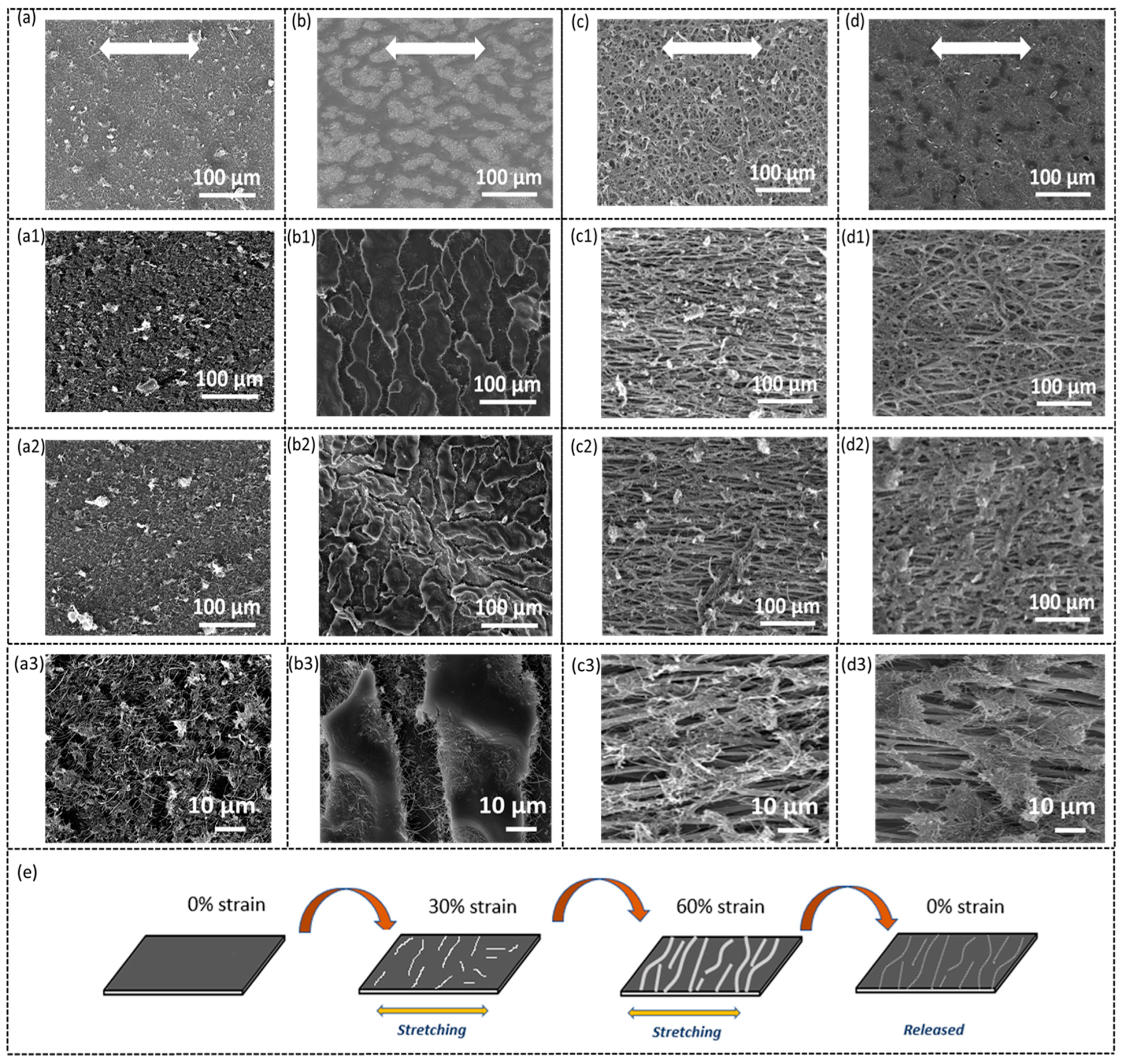
| S-TPU-CNF-AS | Solid TPU thin film with air-sprayed CNFs |
| S-TPU-CNF-ES | Solid TPU thin film with electro-sprayed CNFs |
| NF-TPU-CNF-AS | Nanofiber TPU with air-sprayed CNFs |
| NF-TPU-CNF-ES | Nanofiber TPU with electro-sprayed CNFs |
Disclaimer/Publisher’s Note: The statements, opinions and data contained in all publications are solely those of the individual author(s) and contributor(s) and not of MDPI and/or the editor(s). MDPI and/or the editor(s) disclaim responsibility for any injury to people or property resulting from any ideas, methods, instructions or products referred to in the content. |
© 2023 by the authors. Licensee MDPI, Basel, Switzerland. This article is an open access article distributed under the terms and conditions of the Creative Commons Attribution (CC BY) license (https://creativecommons.org/licenses/by/4.0/).
Share and Cite
Karlapudi, M.C.; Vahdani, M.; Bandari, S.M.; Peng, S.; Wu, S. A Comparative Study on the Effects of Spray Coating Methods and Substrates on Polyurethane/Carbon Nanofiber Sensors. Sensors 2023, 23, 3245. https://doi.org/10.3390/s23063245
Karlapudi MC, Vahdani M, Bandari SM, Peng S, Wu S. A Comparative Study on the Effects of Spray Coating Methods and Substrates on Polyurethane/Carbon Nanofiber Sensors. Sensors. 2023; 23(6):3245. https://doi.org/10.3390/s23063245
Chicago/Turabian StyleKarlapudi, Mounika Chowdary, Mostafa Vahdani, Sheyda Mirjalali Bandari, Shuhua Peng, and Shuying Wu. 2023. "A Comparative Study on the Effects of Spray Coating Methods and Substrates on Polyurethane/Carbon Nanofiber Sensors" Sensors 23, no. 6: 3245. https://doi.org/10.3390/s23063245
APA StyleKarlapudi, M. C., Vahdani, M., Bandari, S. M., Peng, S., & Wu, S. (2023). A Comparative Study on the Effects of Spray Coating Methods and Substrates on Polyurethane/Carbon Nanofiber Sensors. Sensors, 23(6), 3245. https://doi.org/10.3390/s23063245