

Multi-Ring Disk Resonator with Elliptic Spokes for Frequency-Modulated Gyroscope

Abstract
:1. Introduction
2. Materials and Methods
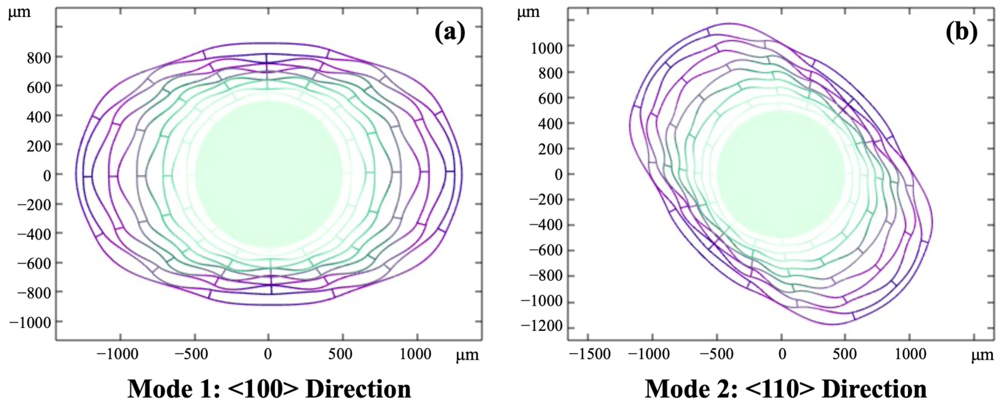
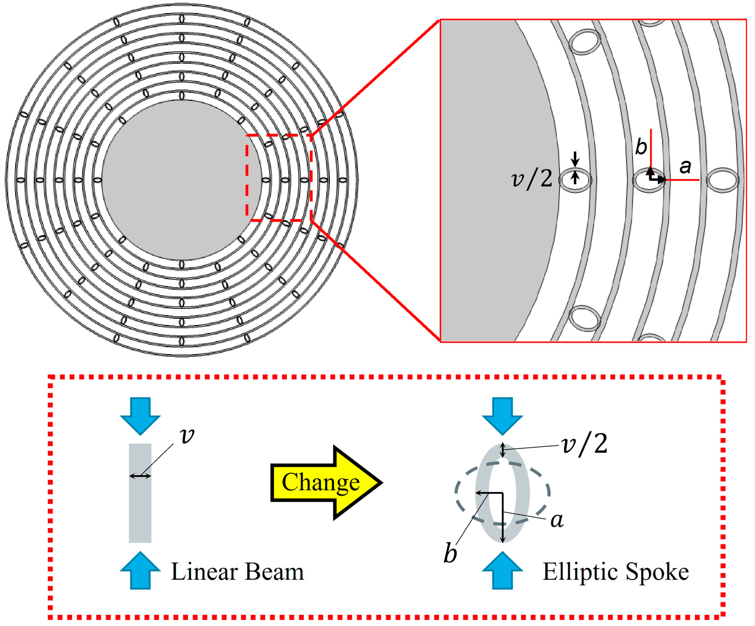
2.1. Working Principle
2.2. Numerical Simulation
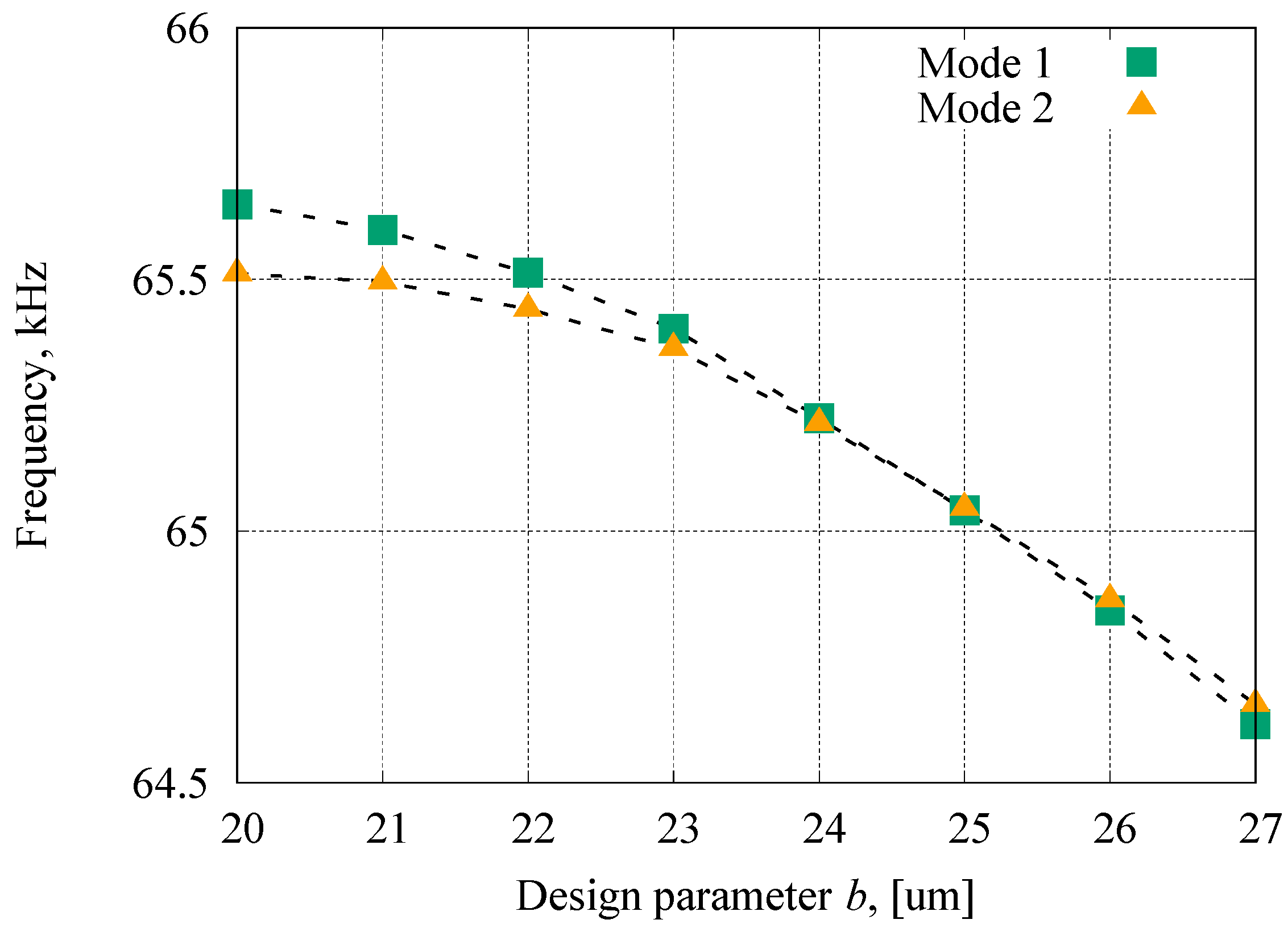
2.2.1. Resonant Frequencies
2.2.2. Quality Factors
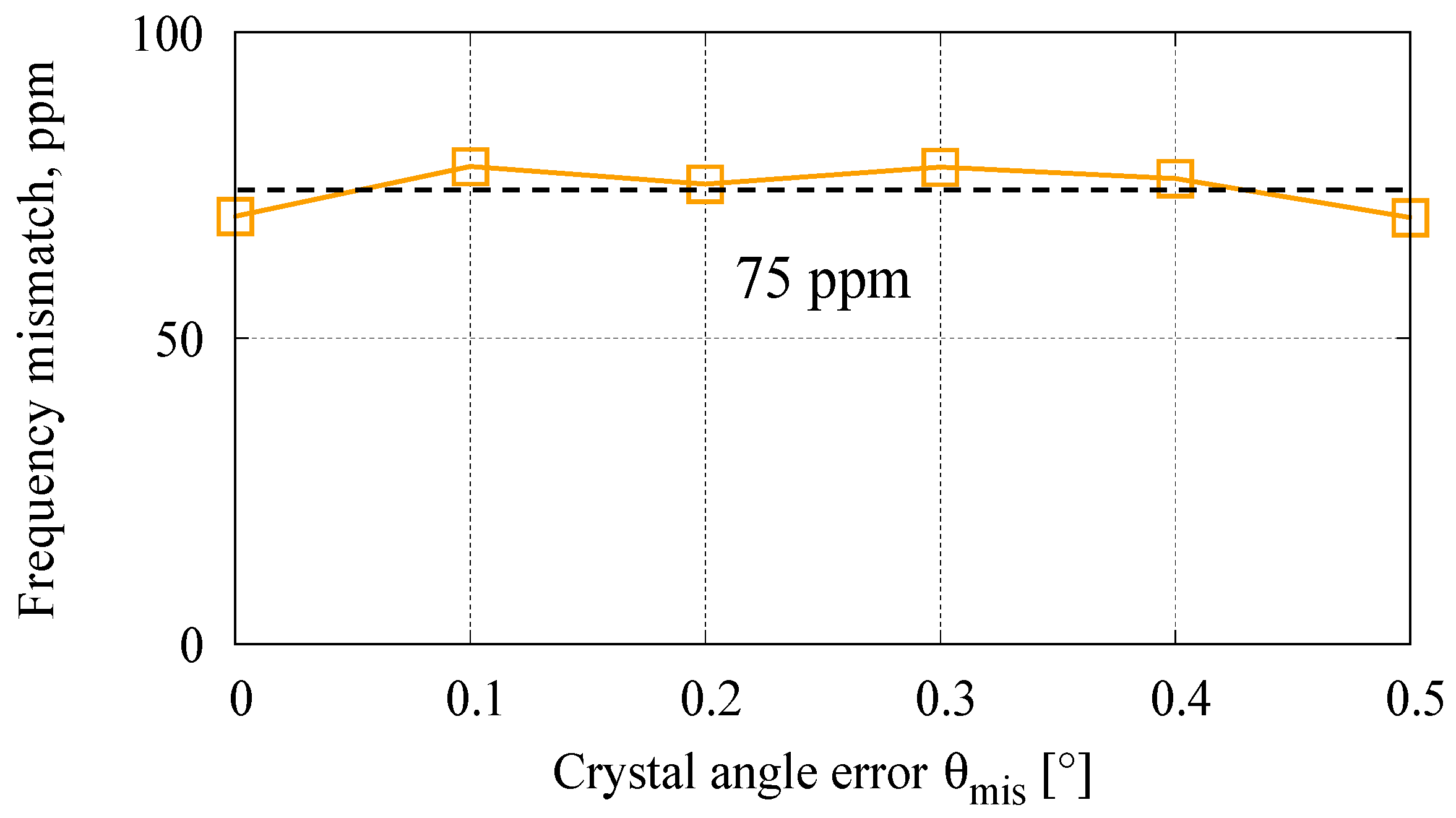
2.2.3. Robustness against Fabrication Error
3. Results
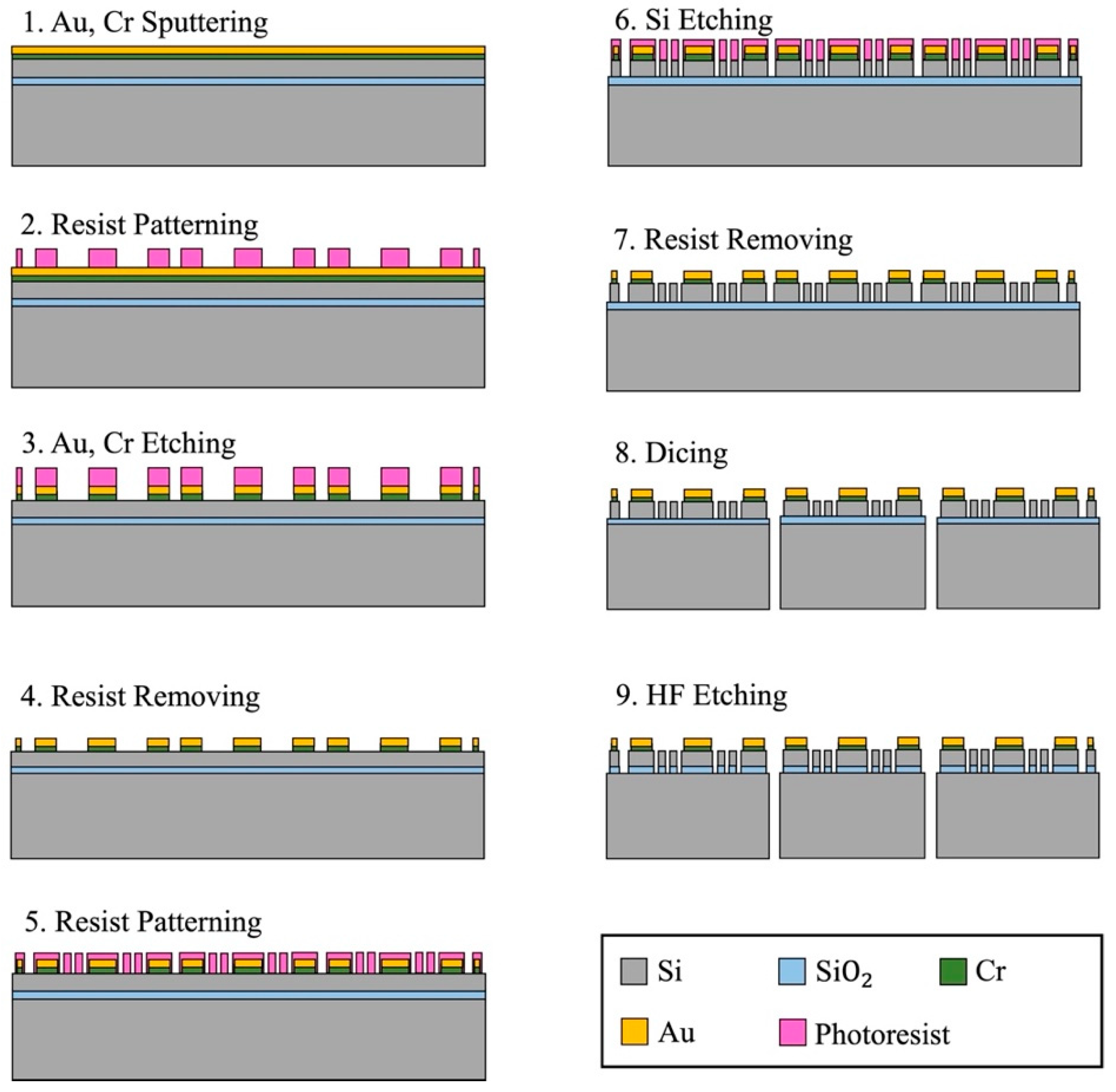
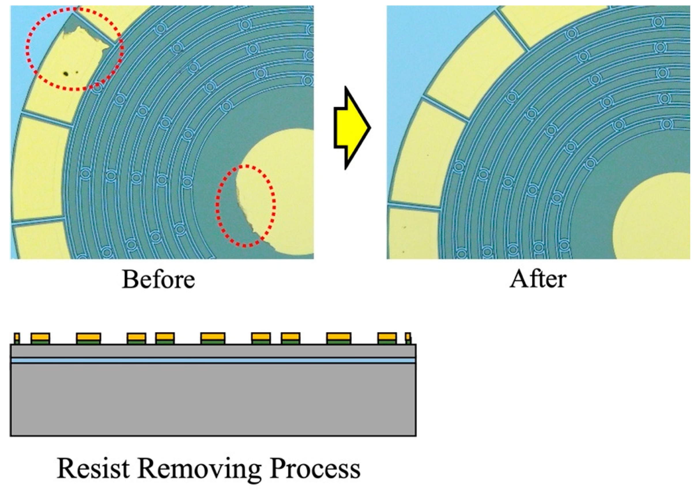
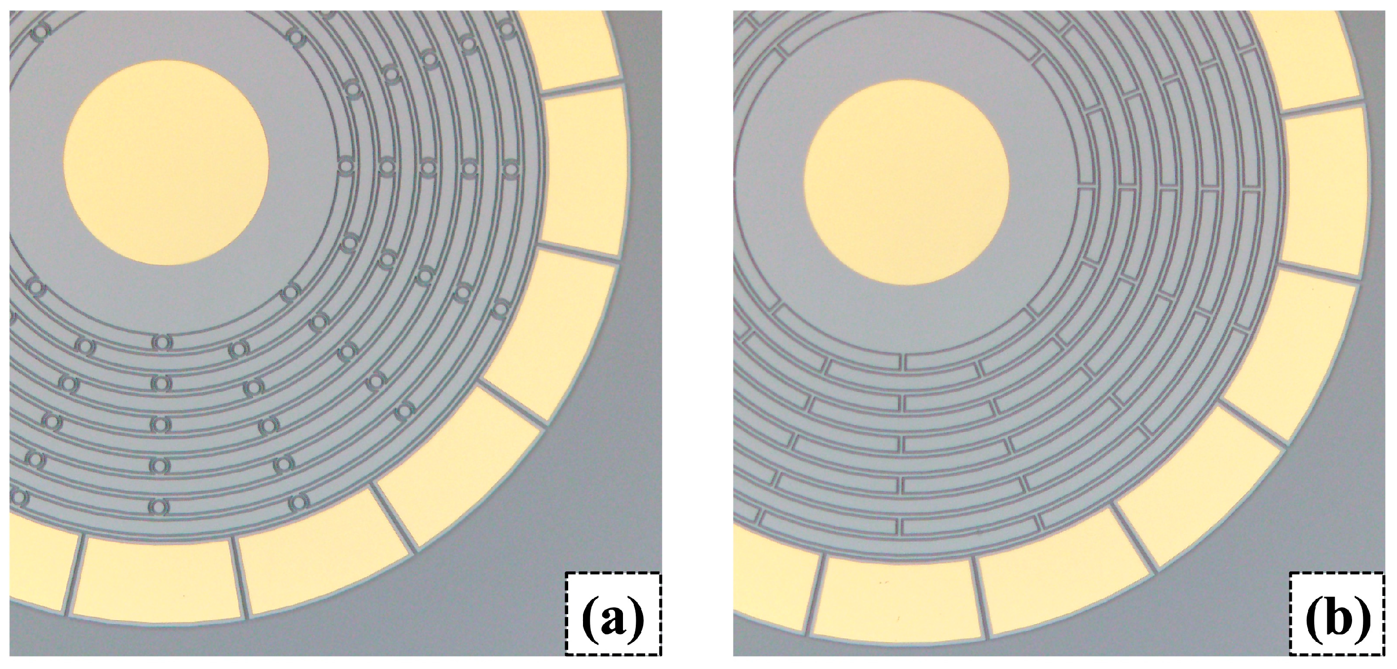
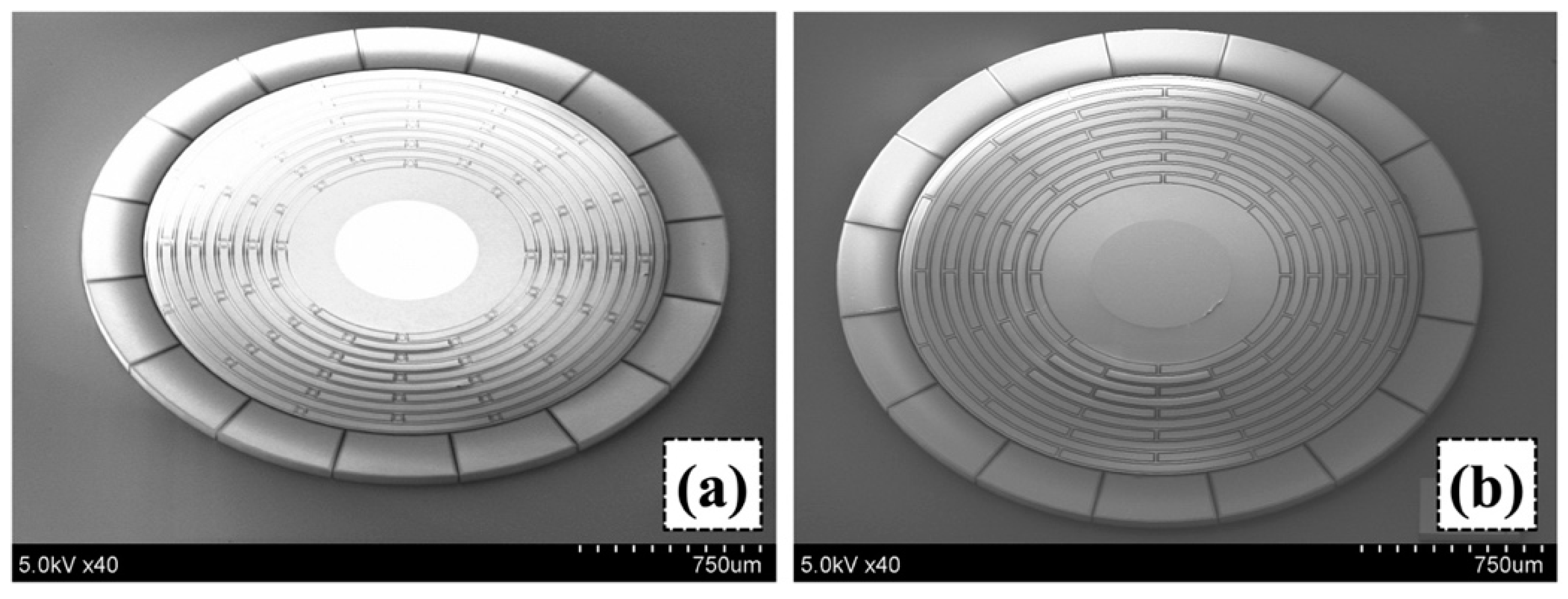
3.1. Device Fabrication
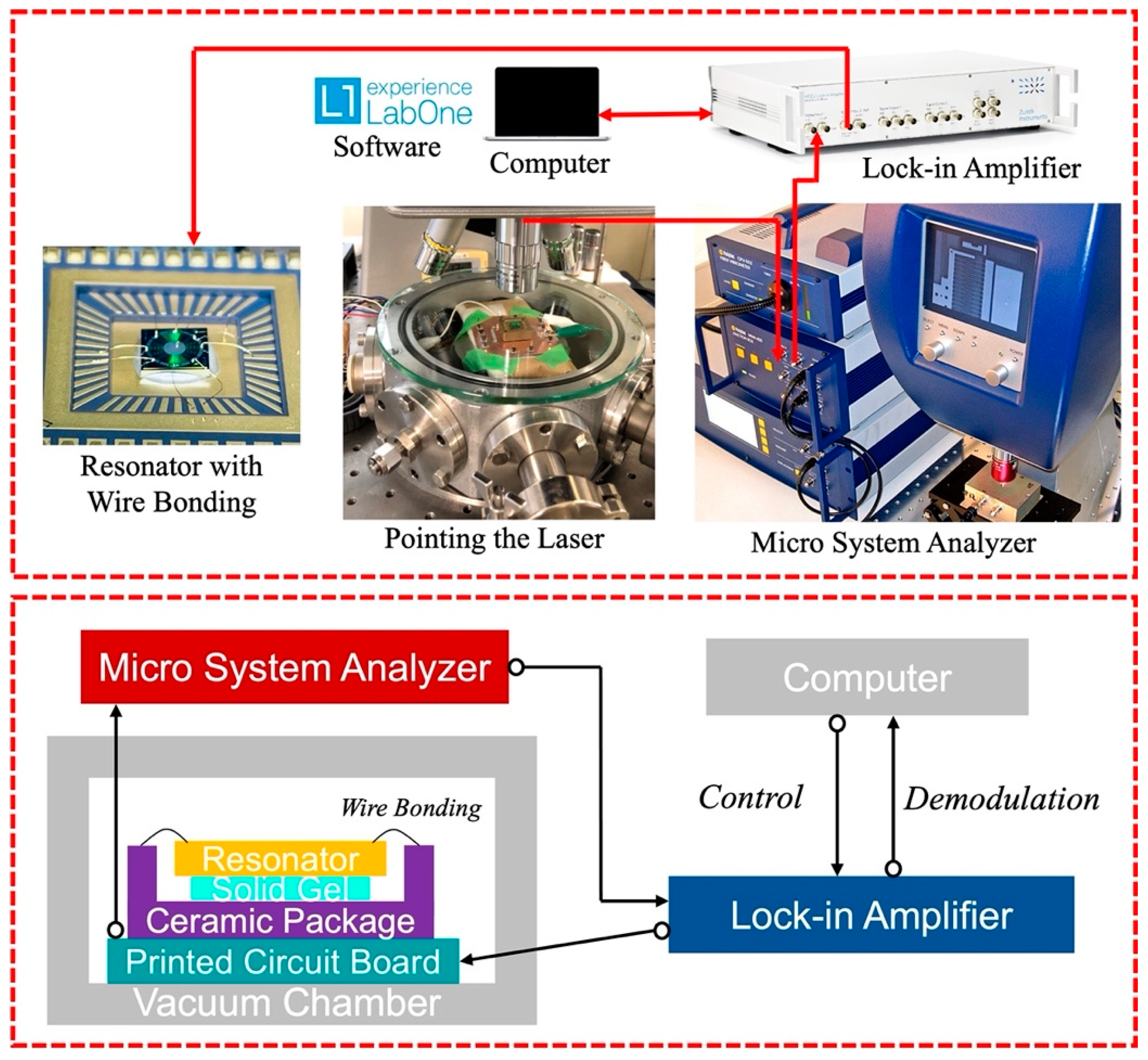
3.2. Evaluation
4. Discussion
5. Conclusions
Author Contributions
Funding
Institutional Review Board Statement
Informed Consent Statement
Data Availability Statement
Conflicts of Interest
References
- Zega, V.; Comi, C.; Fedeli, P.; Frangi, A.; Corigliano, A.; Minotti, P.; Langfelder, G.; Falorni, L.; Tocchio, A. A dual-mass frequency-modulated (FM) pitch gyroscope: Mechanical design and modelling. In Proceedings of the IEEE International Symposium on Inertial Sensors Systems (INERTIAL), Lake Como, Italy, 26–29 March 2018. [Google Scholar]
- Tsukamoto, T.; Tanaka, S. Fully-differential single resonator FM/whole angle gyroscope using CW/CCW mode separator. In Proceedings of the IEEE 30th International Conference on Micro Electro Mechanical Systems (MEMS), Las Vegas, NV, USA, 22–26 January 2017. [Google Scholar]
- Gill, W.A.; Howard, I.; Mazhar, I.; McKee, K. A Review of MEMS Vibrating Gyroscopes and Their Reliability Issues in Harsh Environments. Sensors 2022, 22, 7405. [Google Scholar] [CrossRef] [PubMed]
- Sharma, A.; Zaman, M.F.; Ayazi, F. A Sub-0.2-hr Bias Drift Micromechanical Silicon Gyroscope with Automatic CMOS Mode-Matching. IEEE J. Solid-State Circuits 2009, 44, 1593–1608. [Google Scholar] [CrossRef]
- Jia, J.; Ding, X.; Qin, Z.; Ruan, Z.; Li, W.; Liu, X.; Li, H. Overview and analysis of MEMS Coriolis vibratory ring gyroscope. Measurement 2021, 182, 109704. [Google Scholar] [CrossRef]
- Xuan, L.; Lu, M.; Liu, J.; Guo, S.; Xu, D. Automatic Rate and Rate-Integrating Mode-Switchable Axisymmetric Gyroscope. Sensors 2022, 22, 4334. [Google Scholar] [CrossRef]
- Langfelder, G.; Minotti, P.; Zega, V.; Comi, C.; Marra, C.R.; Leoncini, M.; Bestetti, M. Frequency Modulated Mems Gyroscopes: Recent Developments, Challenges and Outlook. In Proceedings of the 2019 20th International Conference on Solid-State Sensors, Actuators and Microsystems & Eurosensors XXXIII (TRANSDUCERS & EUROSENSORS XXXIII), Berlin, Germany, 23–27 June 2019. [Google Scholar]
- Ren, X.; Zhou, X.; Yu, S.; Wu, X.; Xiao, D. Frequency-Modulated MEMS Gyroscopes: A Review. IEEE Sens. J. 2021, 21, 26426–26446. [Google Scholar] [CrossRef]
- Wang, X.; Zheng, X.; Shen, Y.; Xia, C.; Liu, G.; Jin, Z.; Ma, Z. A Digital Control Structure for Lissajous Frequency-Modulated Mode MEMS Gyroscope. IEEE Sens. J. 2022, 22, 19207–19219. [Google Scholar] [CrossRef]
- Kline, M.; Yeh, Y.; Eminoglu, B.; Najar, H.; Daneman, M.; Horsley, D.; Boser, B. Quadrature FM gyroscope. In Proceedings of the IEEE 26th International Conference on Micro Electro Mechanical Systems (MEMS), Taiwan, 20–24 January 2013. [Google Scholar]
- Tsukamoto, T.; Tanaka, S. Fully Differential Single Resonator FM Gyroscope Using CW/CCW Mode Separator. J. Microelectromechanical Syst. 2018, 27, 985–994. [Google Scholar] [CrossRef]
- Eminoglu, B.; Yeh, Y.C.; Izyumin, I.I.; Nacita, I.; Wireman, M.; Reinelt, A.; Boser, B.E. Comparison of long-term stability of AM versus FM gyroscopes. In Proceedings of the IEEE 26th International Conference on Micro Electro Mechanical Systems (MEMS), Shanghai, China, 24–28 January 2016. [Google Scholar]
- Izyumin, I.I.; Kline, M.H.; Yeh, Y.C.; Eminoglu, B.; Ahn, C.H.; Hong, V.A.; Yang, Y.; Ng, E.J.; Kenny, T.W.; Boser, B.E. A 7ppm, 6°/hr frequency-output MEMS gyroscope. In Proceedings of the IEEE 25th International Conference on Micro Electro Mechanical Systems (MEMS), Estoril, Portugal, 18–22 January 2015. [Google Scholar]
- Minotti, P.; Mussi, G.; Dellea, S.; Bonfanti, A.; Lacaita, A.L.; Langfelder, G.; Zega, V.; Comi, C.; Facchinetti, S.; Tocchio, A. A 160 uA, 8 mdps/Hz Frequency-Modulated MEMS Yaw Gyroscope. In Proceedings of the 2017 IEEE International Symposium on Inertial Sensors and Systems (INERTIAL), Kauai, HI, USA, 27–30 March 2017. [Google Scholar]
- Senkal, D.; Efimovskaya, A.; Shkel, A.M. Dual Foucault Pendulum gyroscope. In Proceedings of the 18th International Conference on Solid-State Sensors, Actuators and Microsystems (TRANSDUCERS), Anchorage, AK, USA, 21–25 June 2015. [Google Scholar]
- Chen, J.; Tsukamoto, T.; Langfelder, G.; Tanaka, S. Frequency and Quality Factor Matched 2-Axis Dual Mass Resonator. In Proceedings of the IEEE Sensors, Sydney, Australia, 31 October–3 November 2021. [Google Scholar]
- Zega, V.; Comi, C.; Minotti, P.; Langfelder, G.; Falorni, L.; Corigliano, A. A new MEMS three-axial frequency-modulated (FM) gyroscope: A mechanical perspective. Eur. J. Mech.-A/Solids 2018, 70, 203–212. [Google Scholar] [CrossRef]
- Senkal, D.; Efimovskaya, A.; Shkel, A.M. Minimal realization of dynamically balanced lumped mass WA gyroscope: Dual foucault pendulum. In Proceedings of the 2015 IEEE International Symposium on Inertial Sensors and Systems (ISISS), Hapuna Beach, HI, USA, 23–26 March 2015. [Google Scholar]
- Efimovskaya, A.; Wang, D.; Lin, Y.-W.; Shkel, A.M. Electrostatic compensation of structural imperfections in dynamically amplified dual-mass gyroscope. Sens. Actuators A Phys. 2018, 275, 99–108. [Google Scholar] [CrossRef]
- Wu, G.; Chua, G.; Gu, Y. A dual-mass fully decoupled MEMS gyroscope with wide bandwidth and high linearity. Sens. Actuators A Phys. 2017, 259, 50–56. [Google Scholar] [CrossRef]
- Wang, S.; Al Farisi, M.S.; Chen, J.; Tsukamoto, T.; Tanaka, S. Dual-Mass Resonator with Dynamically Balanced Structure for Roll/Pitch Rate Integrating Gyroscope. In Proceedings of the IEEE Sensors, Sydney, Australia, 31 October–3 November 2021. [Google Scholar]
- He, G.; Najafi, K. A single-crystal silicon vibrating ring gyroscope. In Proceedings of the Technical Digest, MEMS 2002 IEEE International Conference, Fifteenth IEEE International Conference on Micro Electro Mechanical Systems, Las Vegas, NV, USA, 24 January 2002. [Google Scholar]
- Guo, T.; Wei, W.; Cai, Q.; Cui, R.; Shen, C.; Cao, H. Design and Fabrication of a Novel Wheel-Ring Triaxial Gyroscope. Sensors 2022, 22, 9978. [Google Scholar] [CrossRef] [PubMed]
- Ranji, A.R.; Damodaran, V.; Li, K.; Chen, Z.; Alirezaee, S.; Ahamed, M.J. Recent Advances in MEMS-Based 3D Hemispherical Resonator Gyroscope (HRG)—A Sensor of Choice. Micromachines 2022, 13, 1676. [Google Scholar] [CrossRef] [PubMed]
- Wang, D.; Guan, W.; Asadian, M.H.; Shkel, A.M. Effect of Metallization on Fused Silica Dual-Shell Gyroscopes. In Proceedings of the IEEE International Symposium on Inertial Sensors and Systems (INERTIAL), Avignon, France, 8–11 May 2022. [Google Scholar]
- Wang, D.; Asadian, M.H.; Guan, W.; Hii, D.; Parrish, A.R.; Shkel, A.M. Effect of Metallization on Quality Factor and Noise Characteristics in Fused Silica Dual-Shell Gyroscopes. J. Microelectromechanical Syst. 2022, 31, 877–887. [Google Scholar] [CrossRef]
- Taheri-Tehrani, P.; Izyumin, O.; Izyumin, I.; Ahn, C.H.; Ng, E.J.; Hong, V.A.; Yang, Y.; Kenny, T.W.; Boser, B.E.; Horsley, D.A. Disk resonator gyroscope with whole-angle mode operation. In Proceedings of the 2015 IEEE International Symposium on Inertial Sensors and Systems (ISISS), Hapuna Beach, HI, USA, 23 March 2015. [Google Scholar]
- Li, Q.; Xiao, D.; Zhou, X.; Xu, Y.; Zhuo, M.; Hou, Z.; He, K.; Zhang, Y.; Wu, X. 0.04 degree-per-hour MEMS disk resonator gyroscope with high-quality factor (510 k) and long decaying time constant (74.9 s). Microsyst. Nanoeng. 2018, 4, 32. [Google Scholar] [CrossRef] [PubMed]
- Qin, Z.; Ding, X.; Ge, X.; Ruan, Z.; Li, H. A mode order optimized disk resonator gyroscope considering thermoelastic damping. Int. J. Mech. Sci. 2022, 236, 107737. [Google Scholar] [CrossRef]
- Cho, J.Y.; Singh, S.; Woo, J.K.; He, G.; Najafi, K. 0.00016 deg/√hr Angle Random Walk (ARW) and 0.0014 deg/hr Bias Instability (BI) from a 5.2M-Q and 1-cm Precision Shell Integrating (PSI) Gyroscope. In Proceedings of the IEEE International Symposium on Inertial Sensors and Systems (INERTIAL), Hiroshima, Japan, 23–26 May 2020. [Google Scholar]
- Wang, H.; Xie, J.; Chang, H. A Configurable Measurement Range and Bandwidth Mems Disk Resonator Gyroscope. In Proceedings of the 21st International Conference on Solid-State Sensors, Actuators and Microsystems (Transducers), Orlando, FL, USA, 20–25 June 2021. [Google Scholar]
- HyuckAhn, C.; Shin, D.D.; Hong, V.A.; Yang, Y.; Ng, E.J.; Chen, Y.; Flader, I.B.; Kenny, T.W. Encapsulated disk resonator gyroscope with differential internal electrodes. In Proceedings of the IEEE 29th International Conference on Micro Electro Mechanical Systems (MEMS), Shanghai, China, 24–28 January 2016. [Google Scholar]
- Ayazi, F.; Najafi, K. Design and fabrication of high-performance polysilicon vibrating ring gyroscope. In Proceedings of the MEMS 98. IEEE. Eleventh Annual International Workshop on Micro Electro Mechanical Systems. An Investigation of Micro Structures, Sensors, Actuators, Machines and Systems, Heidelberg, Germany, 25 January 1998. [Google Scholar]
- Nitzan, S.; Ahn, C.H.; Su, T.H.; Li, M.; Ng, E.J.; Wang, S.; Yang, Z.M.; O’brien, G.; Boser, B.E.; Kenny, T.W.; et al. Epitaxially-encapsulated polysilicon disk resonator gyroscope. In Proceedings of the IEEE 26th International Conference on Micro Electro Mechanical Systems (MEMS), Taiwan, 20–24 January 2013. [Google Scholar]
- Johari, H.; Ayazi, F. High-frequency capacitive disk gyroscopes in (100) and (111) silicon. In Proceedings of the IEEE 20th International Conference on Micro Electro Mechanical Systems (MEMS), Hyogo, Japan, 21–25 January 2007. [Google Scholar]
- Zaman, M.F.; Sharma, A.; Ayazi, F. The Resonating Star Gyroscope: A Novel Multiple-Shell Silicon Gyroscope with Sub-5 deg/hr Allan Deviation Bias Instability. IEEE Sens. J. 2009, 9, 616–624. [Google Scholar] [CrossRef]
- Shu, Y.; Hirai, Y.; Tsuchiya, T.; Tabata, O. Geometrical compensation for mode-matching of a (100) silicon ring resonator for a vibratory gyroscope. Jpn. J. Appl. Phys. 2019, 58. [Google Scholar] [CrossRef]
- Ahn, C.H.; Ng, E.J.; Hong, V.A.; Yang, Y.; Lee, B.J.; Flader, I.; Kenny, T.W. Mode-Matching of Wineglass Mode Disk Resonator Gyroscope in (100) Single Crystal Silicon. J. Microelectromechanical Syst. 2014, 24, 343–350. [Google Scholar] [CrossRef]
- Xiao, D.; Yu, D.; Zhou, X.; Hou, Z.; He, H.; Wu, X. Frequency Tuning of a Disk Resonator Gyroscope via Stiffness Perturbation. IEEE Sens. J. 2017, 17, 4725–4734. [Google Scholar] [CrossRef]
- Shcheglov, K.V.; Dorian Challoner, A. Isolated Planar Gyroscope with Internal Radial Sensing and Actuation. U.S. Patent 7040163, 9 May 2006. [Google Scholar]
- Abdelli, H.; Tsukamoto, T.; Tanaka, S. Frequency Trimming Method for a Disk Resonator Using Flexural Rigidity. IEEJ Trans. Sens. Micromachines 2021, 141, 402–408. [Google Scholar] [CrossRef]
- Abdelli, H.; Tsukamoto, T.; Tanaka, S. Quality factor trimming method using thermoelastic dissipation for multi-ring resonator. Sens. Actuators A Phys. 2021, 332, 113044. [Google Scholar] [CrossRef]
- Duwel, A.; Weinstein, M.; Gorman, J.; Borenstein, J.; Ward, P. Quality factors of MEMS gyros and the role of thermoelastic damping. In Proceedings of the Technical Digest. MEMS 2002 IEEE International Conference, Fifteenth IEEE International Conference on Micro Electro Mechanical Systems, Las Vegas, NV, USA, 24 January 2002. [Google Scholar]
- Zener, C. Internal Friction in Solids. I. Theory of Internal Friction in Reeds. Phys. Rev. 1937, 52, 230–235. [Google Scholar] [CrossRef]
- Wang, S.; Chen, J.; Tsukamoto, T.; Tanaka, S. Mode-Matched Multi-Ring Disk Resonator Using (100) Single Crystal Silicon. In Proceedings of the IEEE 35th International Conference on Micro Electro Mechanical Systems (MEMS), Tokyo, Japan, 9–13 January 2022. [Google Scholar]
- Zhang, L.; Tsukamoto, T.; Tanaka, S. Problems in Fabrication of Metal Pads for Capacitive MEMS Using Hands-on Open Facility. IEEJ Trans. Sens. Micromachines 2022, 142, 220–223. [Google Scholar] [CrossRef]
- Gando, R.; Maeda, S.; Masunishi, K.; Tomizawa, Y.; Ogawa, E.; Hatakeyama, Y.; Itakura, T.; Ikehashi, T. A MEMS rate inte-grating gyroscope based on catch-and-release mechanism for low-noise continuous angle measurement. In Proceedings of the IEEE 31st International Conference on Micro Electro Mechanical Systems (MEMS), Belfast, UK, 21–25 January 2018. [Google Scholar]
- Yan, J.; Miao, L.; Chen, M.; Huang, T.; Che, S.; Shu, X. Research on the feedback control characteristics and parameter optimization of closed-loop fiber optic gyroscope. Optik 2021, 229, 166298. [Google Scholar] [CrossRef]
- Prikhodko, I.P.; Zotov, S.A.; Trusov, A.A.; Shkel, A.M. Foucault pendulum on a chip: Rate integrating silicon MEMS gyroscope. Sens. Actuators A Phys. 2012, 177, 67–78. [Google Scholar] [CrossRef]
- Woo, J.K.; Cho, J.Y.; Boyd, C.; Najafi, K. Whole-angle-mode micromachined fused-silica birdbath resonator gyroscope (WA-BRG). In Proceedings of the IEEE 27th International Conference on Micro Electro Mechanical Systems (MEMS), San Francisco, CA, USA, 26–30 January 2014. [Google Scholar]


| Proposed Resonator (with Elliptic Spokes) | Conventional Resonator (with Linear Beams) | |
|---|---|---|
| Thickness | 50 µm | |
| Density | 2330 kg/m3 | |
| Thermal Conductivity | 130 W/m/K | |
| Number of Rings | 10 | |
| Width of Rings | 10 µm | |
| Distance between Rings | 50 µm | |
| Radius of Centre Structure | 500 µm | |
| Resonant Frequency Mismatch | 70 ppm | 44,000 ppm |
| Proposed Resonator (with Elliptic Spokes) | Conventional Resonator (with Linear Beams) | |||
|---|---|---|---|---|
| Device thickness | 50 µm | |||
| Width of rings | 10 µm | |||
| Device ID | 1 | 2 | 3 | 1 |
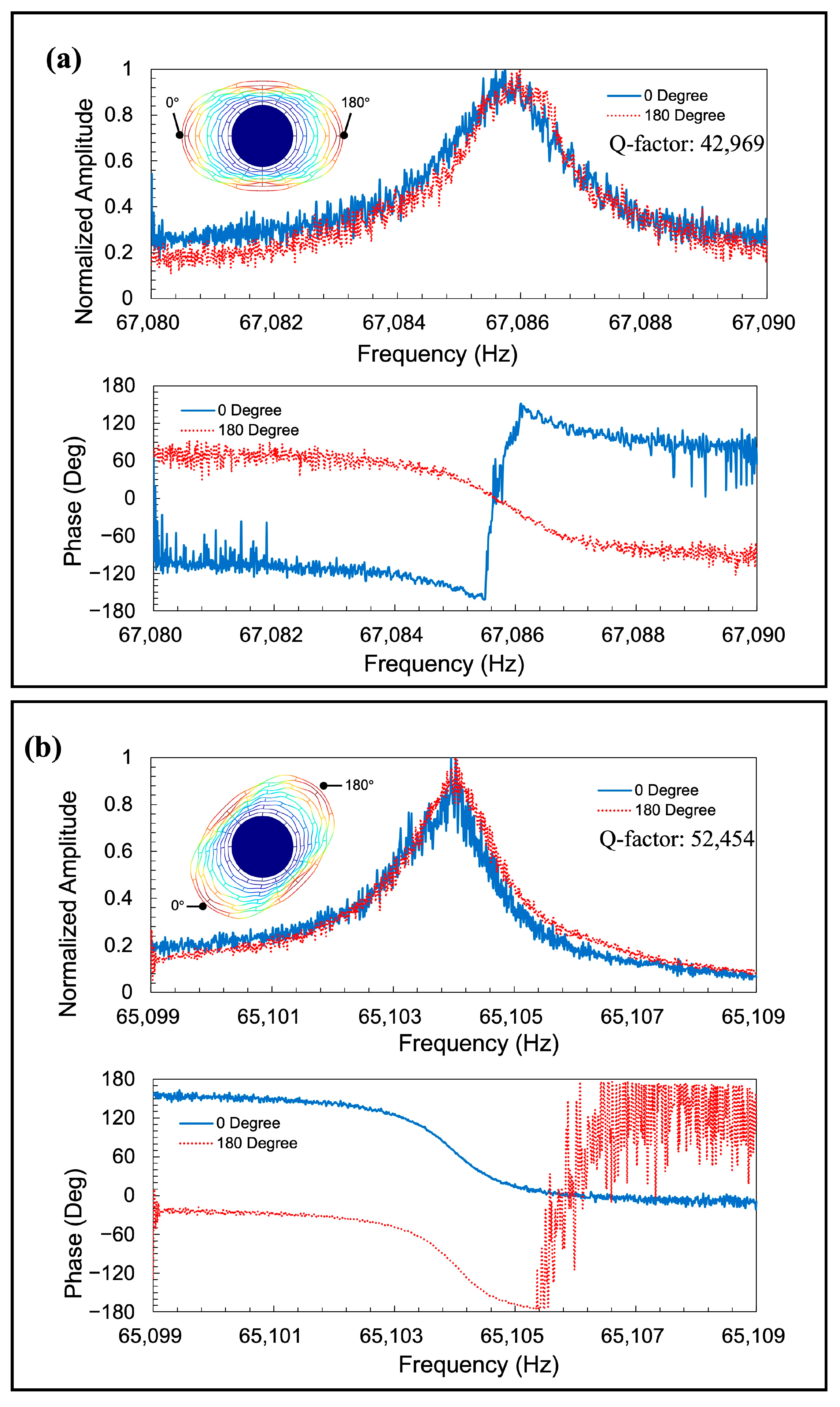
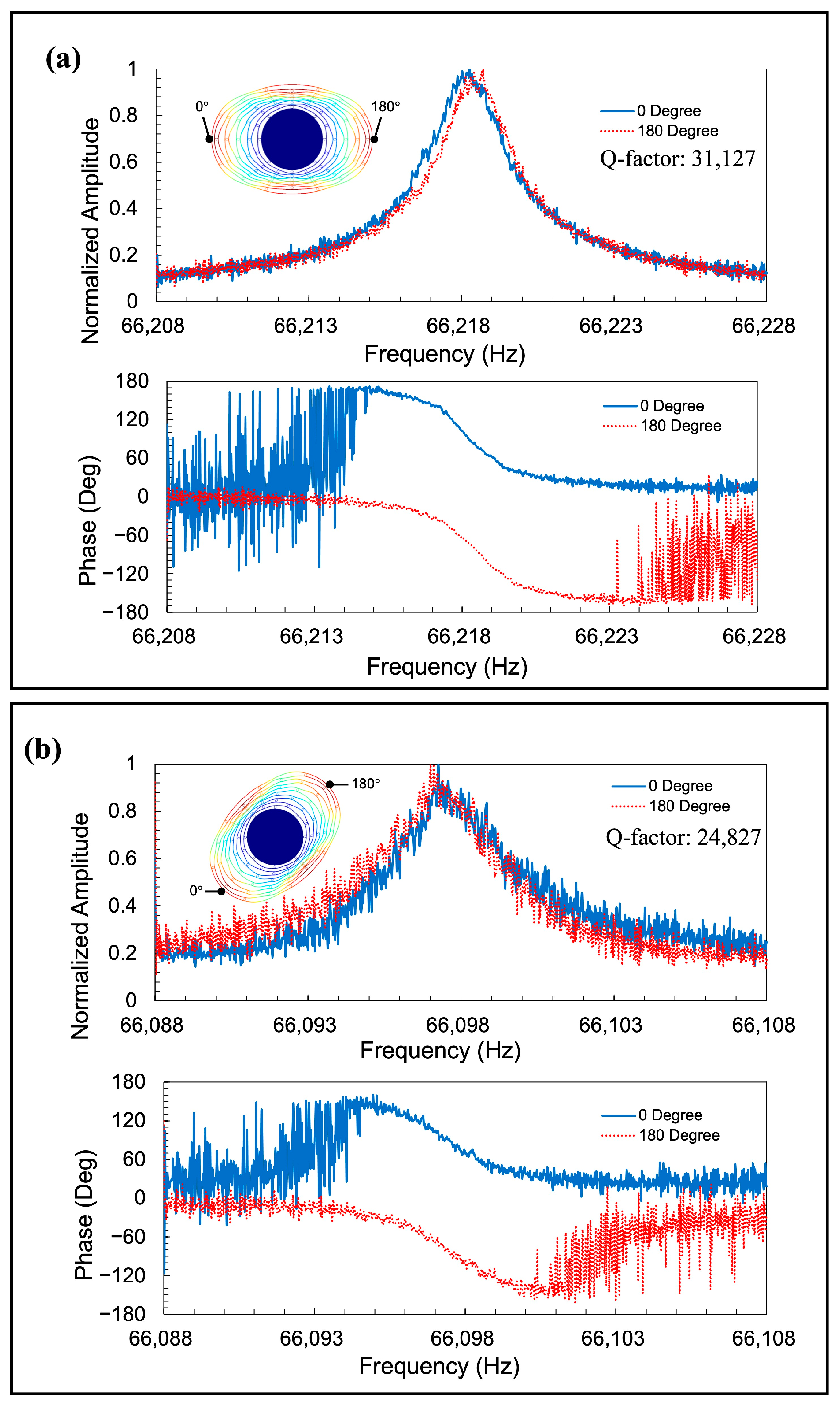
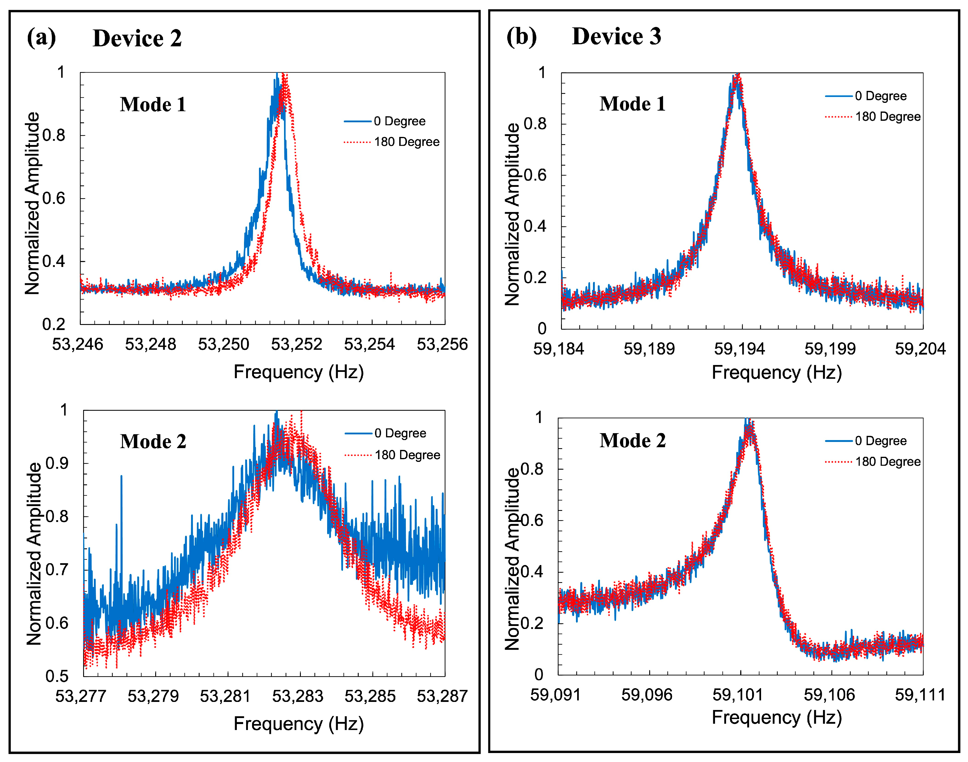
| Q-factor mismatch | 25.4% | 26.2% | 30.4% | 22.1% |
| Mode 1 frequency | 66.218 kHz | 53.252 kHz | 59.194 kHz | 67.086 kHz |
| Mode 2 frequency | 66.097 kHz | 53.283 kHz | 59.101 kHz | 65.104 kHz |
| Frequency Mismatch | 1830 ppm | 580 ppm | 1570 ppm | 30,000 ppm |
Disclaimer/Publisher’s Note: The statements, opinions and data contained in all publications are solely those of the individual author(s) and contributor(s) and not of MDPI and/or the editor(s). MDPI and/or the editor(s) disclaim responsibility for any injury to people or property resulting from any ideas, methods, instructions or products referred to in the content. |
© 2023 by the authors. Licensee MDPI, Basel, Switzerland. This article is an open access article distributed under the terms and conditions of the Creative Commons Attribution (CC BY) license (https://creativecommons.org/licenses/by/4.0/).
Share and Cite
Wang, S.; Chen, J.; Tsukamoto, T.; Tanaka, S. Multi-Ring Disk Resonator with Elliptic Spokes for Frequency-Modulated Gyroscope. Sensors 2023, 23, 2937. https://doi.org/10.3390/s23062937
Wang S, Chen J, Tsukamoto T, Tanaka S. Multi-Ring Disk Resonator with Elliptic Spokes for Frequency-Modulated Gyroscope. Sensors. 2023; 23(6):2937. https://doi.org/10.3390/s23062937
Chicago/Turabian StyleWang, Shihe, Jianlin Chen, Takashiro Tsukamoto, and Shuji Tanaka. 2023. "Multi-Ring Disk Resonator with Elliptic Spokes for Frequency-Modulated Gyroscope" Sensors 23, no. 6: 2937. https://doi.org/10.3390/s23062937
APA StyleWang, S., Chen, J., Tsukamoto, T., & Tanaka, S. (2023). Multi-Ring Disk Resonator with Elliptic Spokes for Frequency-Modulated Gyroscope. Sensors, 23(6), 2937. https://doi.org/10.3390/s23062937