
Variable-Sensitivity Force Sensor Based on Structural Modification

Abstract
:1. Introduction
2. Theory
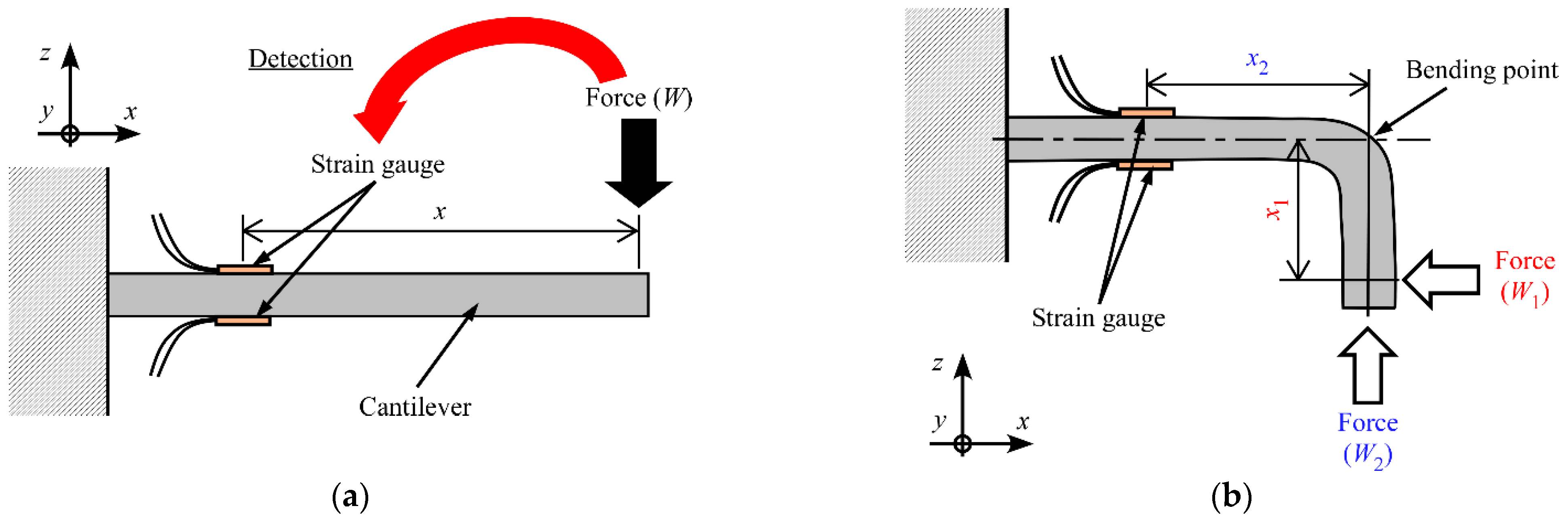
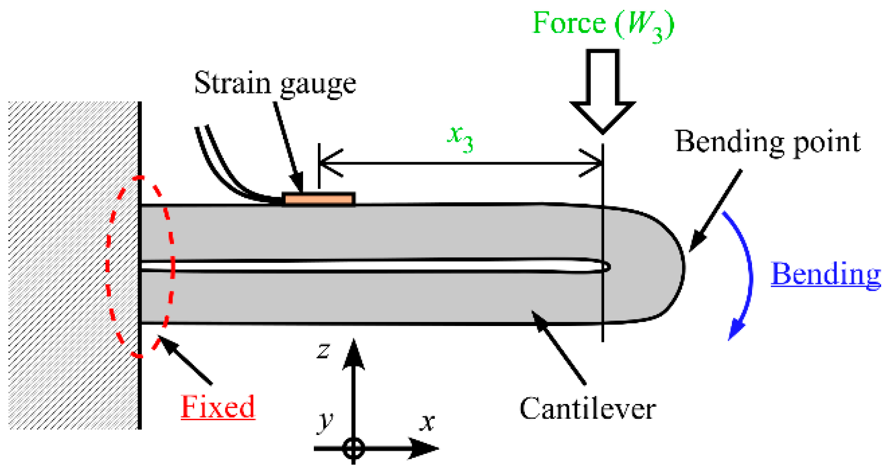
2.1. Change in Distance between Force Application Point and Detection Area
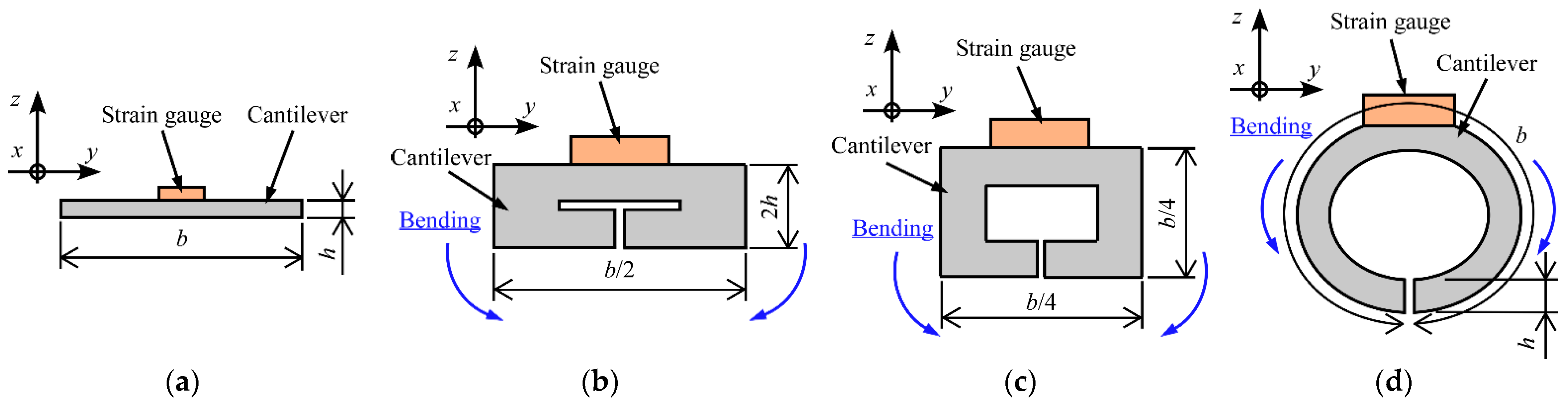
2.2. Change of Cross-Sectional Shape
2.3. Application of SMM
- Lower cost (1/25th that of SMA).
- Lower density (1/7th that of SMA).
- Larger recoverable strains (greater than 400% compared with a maximum of 8% for SMAs).
- Easier creation of the complex shapes in Section 2.1 and Section 2.2 by heating (the change of the elastic modulus of SMP around Tg is large).
- Larger recovery stress (113 times that for SMPs).
- Larger thermal conductivity (80 times that for SMPs).
- Higher electrical conductivity.
3. Experiment
3.1. Prototype Sensors
3.1.1. SMA FS
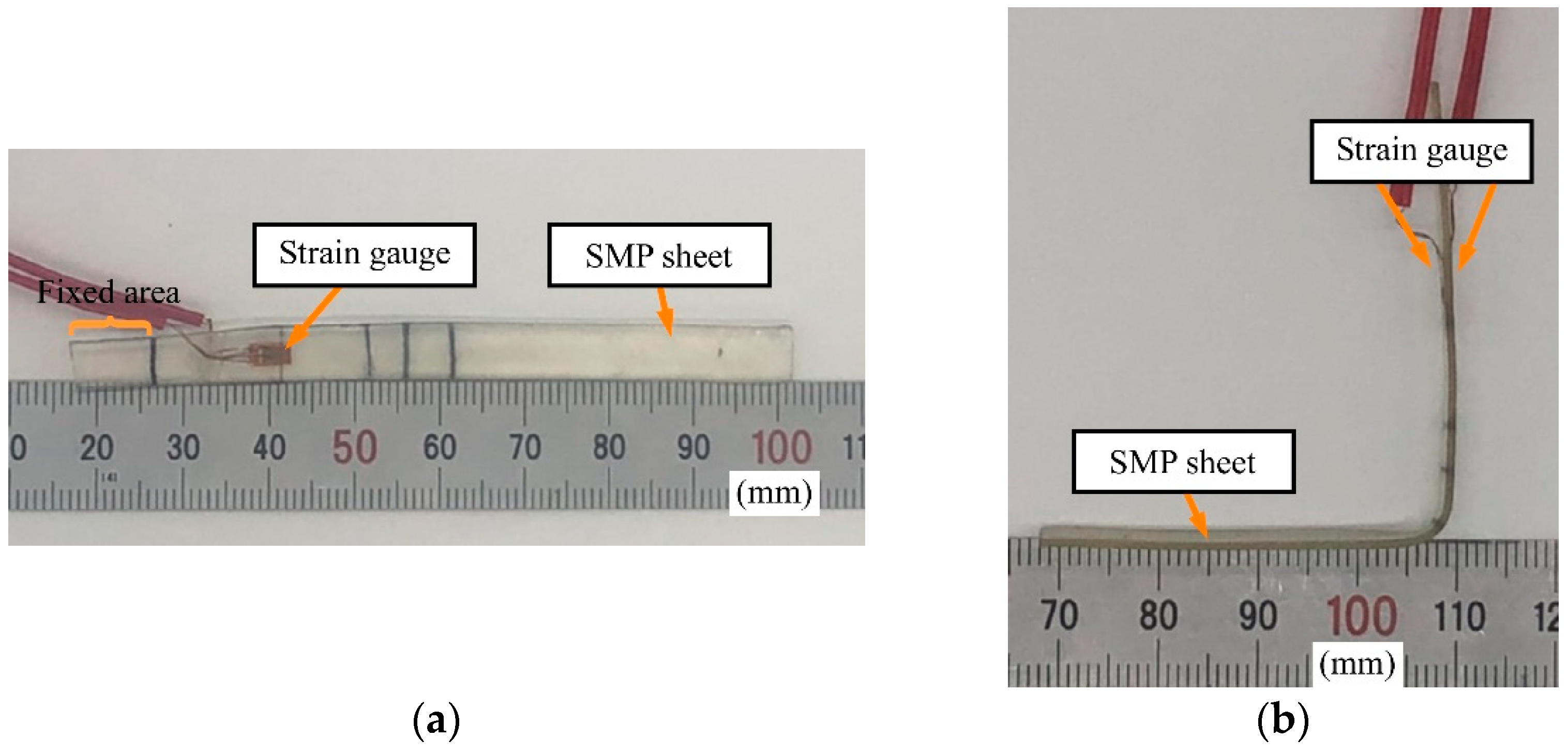
3.1.2. SMP FS
3.2. Methods
- Step 1:
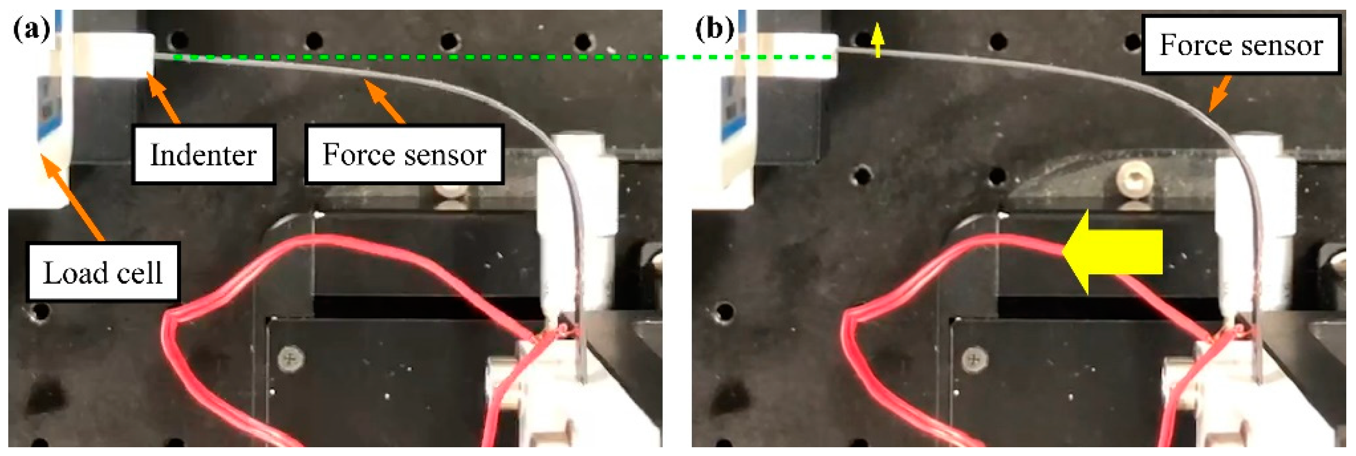
- The sensor was held motionless in the unloaded state (just before touching).
- Step 2:
- After the unloaded state, the sensor was moved in the direction of the blue arrow in Figure 7a and brought into contact with the load cell to apply a deformation of 1 mm to the tip of the sensor.
- Step 3:
- With the tip deformed, the sensor was held motionless.
- Step 4:
- The sensor was returned to the initial position.
4. Results and Discussion
4.1. SMA FS
4.2. SMP FS
5. Conclusions
Author Contributions
Funding
Institutional Review Board Statement
Informed Consent Statement
Data Availability Statement
Conflicts of Interest
References
- Fraden, J. Handbook of Modern Sensors: Physics, Designs, and Applications, 3rd ed.; Springer: Berlin/Heidelberg, Germany, 2003; ISBN 0387007504. [Google Scholar]
- Murozaki, Y.; Sakuma, S.; Arai, F. Improvement of the Measurement Range and Temperature Characteristics of a Load Sensor Using a Quartz Crystal Resonator with All Crystal Layer Components. Sensors 2017, 17, 1067. [Google Scholar] [CrossRef] [PubMed]
- Zhuo, S.; Song, C.; Rong, Q.; Zhao, T.; Liu, M. Shape and stiffness memory ionogels with programmable pressure-resistance response. Nat. Commun. 2022, 13, 1743. [Google Scholar] [CrossRef] [PubMed]
- Sun, X.; Chen, W.; Xiong, X.; Chen, W.; Jin, Y. A Variable Configuration Force Sensor with Adjustable Resolution for Robotic Applications. IEEE Trans. Ind. Electron. 2022, 70, 2066–2075. [Google Scholar] [CrossRef]
- Jiang, J.; Chen, W.; Liu, J.; Chen, W.; Zhang, J. Optimum Design of a Dual-Range Force Sensor for Achieving High Sensitivity, Broad Bandwidth, and Large Measurement Range. IEEE Sens. J. 2015, 15, 1114–1123. [Google Scholar] [CrossRef]
- Okumura, D.; Sakaino, S.; Tsuji, T. High Dynamic Range Sensing by a Multistage Six-Axis Force Sensor with Stopper Mechanism. In Proceedings of the 2018 IEEE International Conference on Robotics and Automation (ICRA), Brisbane, QLD, Australia, 21–25 May 2018; pp. 4065–4070. [Google Scholar] [CrossRef]
- Tamura, R.; Sakaino, S.; Tsuji, T. Development of compact high dynamic range six-axis force sensor with cross-arch structure. In Proceedings of the IECON 2019—45th Annual Conference of the IEEE Industrial Electronics Society, Lisbon, Portugal, 14–17 October 2019; Volume 2019, pp. 3609–3614. [Google Scholar] [CrossRef]
- Tamura, R.; Sakaino, S.; Tsuji, T. High Dynamic Range Uniaxial Force/Torque Sensor Using Metal Foil and Semiconductor Strain Gauge. IEEJ J. Ind. Appl. 2021, 10, 506–511. [Google Scholar] [CrossRef]
- Maroufi, M.; Alemansour, H.; Coskun, M.B.; Moheimani, S.O.R. An adjustable-stiffness MEMS force sensor: Design, characterization, and control. Mechatronics 2018, 56, 198–210. [Google Scholar] [CrossRef]
- Nastro, A.; Ferrari, M.; Ferrari, V. Double-actuator position-feedback mechanism for adjustable sensitivity in electrostatic-capacitive MEMS force sensors. Sens. Actuators A Phys. 2020, 312, 112127. [Google Scholar] [CrossRef]
- Horie, R.; Kaneko, M. A Sensitivity Variable Tactile Sensor with Self-Tuner. J. Robot. Soc. Jpn. 2003, 21, 940–946. (In Japanese) [Google Scholar] [CrossRef]
- Kouno, S. A Sensitivity Variable Tactile Sensor with Self-Tuner. J. Robot. Mechatron. 2006, 18, 83–88. [Google Scholar] [CrossRef]
- Takashima, K.; Kamizono, H.; Takenaka, M.; Mukai, T. Force sensor utilizing stiffness change of shape-memory polymer based on temperature. ROBOMECH J. 2017, 4, 17. [Google Scholar] [CrossRef]
- Takashima, K.; Kobuchi, J.; Kamamichi, N.; Takagi, K.; Mukai, T. Characterization of variable-sensitivity force sensor using stiffness change of shape-memory polymer based on temperature. ROBOMECH J. 2021, 8, 24. [Google Scholar] [CrossRef]
- Takashima, K.; Onoda, R.; Mukai, T. Evaluation of Error and Sensitivity for Force Sensor Using Shape-Memory Polymer. In Proceedings of the 2018 57th Annual Conference of the Society of Instrument and Control Engineers of Japan, SICE 2018, Nara, Japan, 11–14 September 2018; pp. 1433–1438. [Google Scholar]
- Alberto, N.; Fonseca, M.A.; Neto, V.; Nogueira, R.; Oliveira, M.; Moreira, R. Incorporation of Fiber Bragg Sensors for Shape Memory Polyurethanes Characterization. Sensors 2017, 17, 2600. [Google Scholar] [CrossRef] [PubMed]
- Mohd Jani, J.; Leary, M.; Subic, A.; Gibson, M.A. A review of shape memory alloy research, applications and opportunities. Mater. Des. 2014, 56, 1078–1113. [Google Scholar] [CrossRef]
- Japan Institute of Invention and Innovation, “Patent Distribution Support Chart: Shape-Memory Polymers,” National Center for Industrial Property Information and Training. Available online: https://www.inpit.go.jp/blob/katsuyo/pdf/chart/fkagaku32.pdf (accessed on 6 October 2022). (In Japanese)
- Tung, A.T.; Park, B.H.; Liang, D.H.; Niemeyer, G. Laser-machined shape memory alloy sensors for position feedback in active catheters. Sens. Actuators A Phys. 2008, 147, 83–92. [Google Scholar] [CrossRef] [PubMed]
- Terrile, S.; Miguelañez, J.; Barrientos, A. A Soft Haptic Glove Actuated with Shape Memory Alloy and Flexible Stretch Sensors. Sensors 2021, 21, 5278. [Google Scholar] [CrossRef] [PubMed]
- Nahm, S.H.; Kim, Y.J.; Kim, J.M.; Yoon, D.J. A Study on the Application of Ni-Ti Shape Memory Alloy as a Sensor. Mater. Sci. Forum 2005, 475–479, 2043–2046. [Google Scholar] [CrossRef]
- Shibata, T.; Otani, R.; Komai, K.; Inoue, T. Zairyo Rikigaku No Kiso; Baifukan: Tokyo, Japan, 1991. (In Japanese) [Google Scholar]


| Sample No. 1 | Sample No. 2 | Sample No. 3 | |
|---|---|---|---|
| Length, L (mm) | 84.4 ± 0.0 | 86.4 ± 0.1 | 89.5 ± 0.0 |
| Width, b (mm) | 5.2 ± 0.0 | 5.3 ± 0.0 | 5.2 ± 0.0 |
| Thickness, h (mm) | 0.69 ± 0.00 | 0.70 ± 0.00 | 0.70 ± 0.00 |
| x1 (mm) | 34.8 ± 0.4, 44.8 ± 0.4 | 38.5 ± 0.9, 42.6 ± 0.4, 47.8 ± 0.3 | 50.5 ± 0.4, 51.2 ± 0.3 |
| x2 (mm) | 32.8 ± 0.2, 23.8 ± 0.3 | 28.7 ± 0.4, 22.2 ± 0.3, 21.1 ± 0.3 | 13.7 ± 0.2, 18.9 ± 0.5 |
| Width, b (mm) | 6.8 ± 0.0 |
| Thickness, h (mm) | 0.82 ± 0.01 |
| x1 (mm) | 52.0 ± 0.4, 50.6 ± 0.6, 46.4 ± 0.5, 45.2 ± 0.2, 41.0 ± 0.6, 31.3 ± 0.2 |
| x2 (mm) | 13.3 ± 0.3, 12.5 ± 0.3, 16.9 ± 0.4, 17.8 ± 0.2, 21.6 ± 0.3, 31.5 ± 0.3 |
Disclaimer/Publisher’s Note: The statements, opinions and data contained in all publications are solely those of the individual author(s) and contributor(s) and not of MDPI and/or the editor(s). MDPI and/or the editor(s) disclaim responsibility for any injury to people or property resulting from any ideas, methods, instructions or products referred to in the content. |
© 2023 by the authors. Licensee MDPI, Basel, Switzerland. This article is an open access article distributed under the terms and conditions of the Creative Commons Attribution (CC BY) license (https://creativecommons.org/licenses/by/4.0/).
Share and Cite
Takashima, K.; Ota, K.; Cho, H. Variable-Sensitivity Force Sensor Based on Structural Modification. Sensors 2023, 23, 2077. https://doi.org/10.3390/s23042077
Takashima K, Ota K, Cho H. Variable-Sensitivity Force Sensor Based on Structural Modification. Sensors. 2023; 23(4):2077. https://doi.org/10.3390/s23042077
Chicago/Turabian StyleTakashima, Kazuto, Kengo Ota, and Hiroki Cho. 2023. "Variable-Sensitivity Force Sensor Based on Structural Modification" Sensors 23, no. 4: 2077. https://doi.org/10.3390/s23042077
APA StyleTakashima, K., Ota, K., & Cho, H. (2023). Variable-Sensitivity Force Sensor Based on Structural Modification. Sensors, 23(4), 2077. https://doi.org/10.3390/s23042077