

Generalized Design, Modeling and Control Methodology for a Snake-like Aerial Robot

Abstract
1. Introduction
1.1. Related Works
1.1.1. Existing Snake-like Robots
1.1.2. Modular Aerial Robots
1.2. Contributions
- We introduced a generalized design for snake-like aerial robots, including a thrust vectoring apparatus with dual rotors that can generate different thrust forces.
- We presented a generalized modeling method for articulated aerial robots based on an approximated model and further proposed two different actuator allocation strategies according to the number of vectoring apparatus.
- We developed a generalized control framework that utilizes the proposed actuator allocation to enable the stable flight for both under-actuated and fully actuated models.
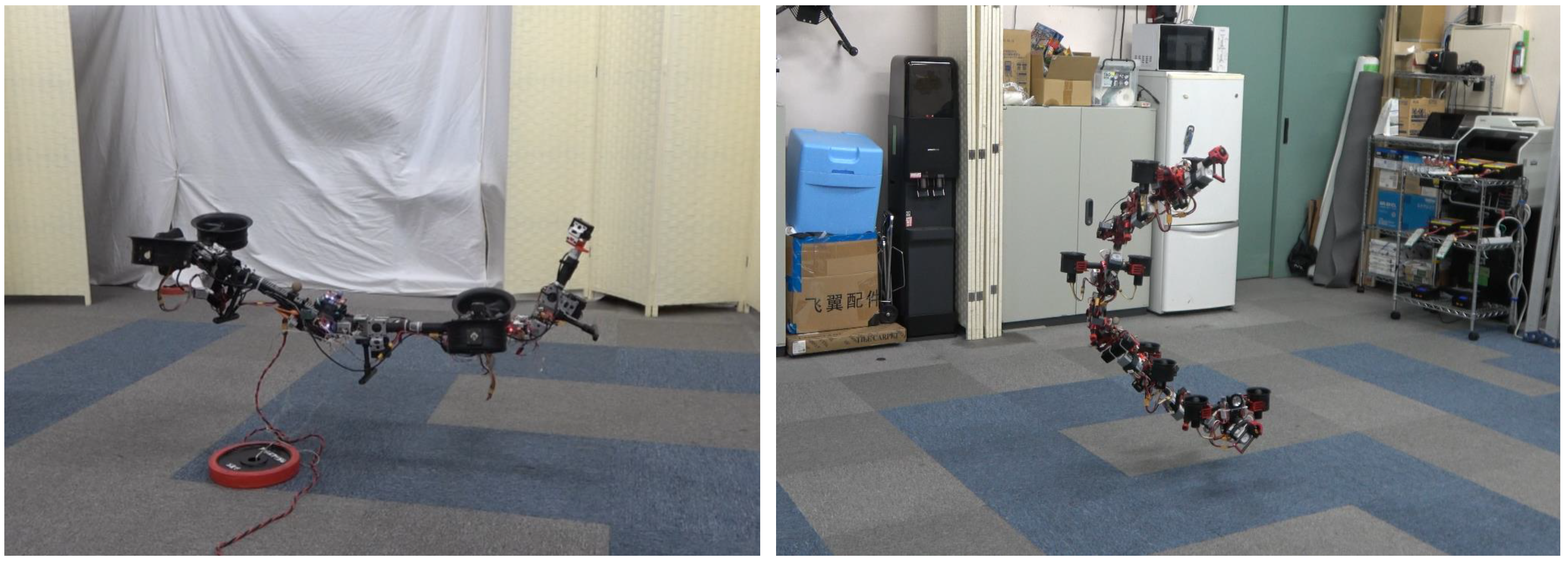
- We performed experiments with two different platforms, as shown in Figure 1, to demonstrate the feasibility of the proposed design, and modeling and control methods for the flight with joint motion in midair.
1.3. Notation
1.4. Organization
2. Generalized Design
2.1. Dual-Rotor Vectoring Apparatus
2.2. Two-DoF Joint Module
3. Generalized Modeling Method
3.1. Approximation Model
3.2. Actuator Allocation
3.2.1. Dual-Rotor Mode
3.2.2. Virtual-Single-Rotor Mode
4. Generalized Control Framework
4.1. Common Framework
4.2. Full Pose Control
4.3. Control Allocation
4.3.1. Under-Actuated Model
4.3.2. Fully Actuated Model
5. Experiments
5.1. Platforms
5.1.1. Under-Actuated Model
5.1.2. Fully Actuated Model
5.2. Flight Experiments
5.2.1. Under-Actuated Robot
5.2.2. Fully Actuated Robot
6. Conclusions
Author Contributions
Funding
Institutional Review Board Statement
Informed Consent Statement
Data Availability Statement
Conflicts of Interest
References
- Gray, J. The Mechanism of Locomotion in Snakes. J. Exp. Biol. 1946, 23, 101–120. [Google Scholar] [CrossRef] [PubMed]
- Hirose, S. Biologically Inspired Robots: Serpentile Locomotors and Manipulators; Cave, P., Goulden, C., Eds.; Oxford University Press, Inc.: Oxford, UK, 1993. [Google Scholar]
- Klaassen, B.; Paap, K. GMD-SNAKE2: A snake-like robot driven by wheels and a method for motion control. In Proceedings of the 1999 IEEE International Conference on Robotics and Automation (Cat. No.99CH36288C), Detroit, MI, USA, 10–15 May 1999; Volume 4, pp. 3014–3019. [Google Scholar] [CrossRef]
- Borenstein, J.; Hansen, M.; Borrell, A. The OmniTread OT-4 serpentine robot—Design and performance. J. Field Robot. 2007, 24, 601–621. [Google Scholar] [CrossRef]
- Wright, C.; Johnson, A.; Peck, A.; McCord, Z.; Naaktgeboren, A.; Gianfortoni, P.; Gonzalez-Rivero, M.; Hatton, R.; Choset, H. Design of a modular snake robot. In Proceedings of the 2007 IEEE/RSJ International Conference on Intelligent Robots and Systems, San Diego, CA, USA, 29 October–2 November 2007; pp. 2609–2614. [Google Scholar] [CrossRef]
- Ostrowski, J.; Burdick, J. Gait kinematics for a serpentine robot. In Proceedings of the IEEE International Conference on Robotics and Automation, Minneapolis, MN, USA, 22–28 April 1996; Volume 2, pp. 1294–1299. [Google Scholar] [CrossRef]
- McIsaac, K.; Ostrowski, J. Motion planning for anguilliform locomotion. IEEE Trans. Robot. Autom. 2003, 19, 637–652. [Google Scholar] [CrossRef]
- Burdick, J.; Radford, J.; Chirikjian, G. A ‘sidewinding’ locomotion gait for hyper-redundant robots. In Proceedings of the IEEE International Conference on Robotics and Automation, Atlanta, GA, USA, 2–6 May 1993; Volume 3, pp. 101–106. [Google Scholar] [CrossRef]
- Chang, A.H.; Vela, P.A. Shape-centric modeling for control of traveling wave rectilinear locomotion on snake-like robots. Robot. Auton. Syst. 2020, 124, 103406. [Google Scholar] [CrossRef]
- Liu, L.; Guo, X.; Fang, Y. A Reinforcement Learning-Based Strategy of Path Following for Snake Robots with an Onboard Camera. Sensors 2022, 22, 9867. [Google Scholar] [CrossRef] [PubMed]
- Transeth, A.A.; Leine, R.I.; Glocker, C.; Pettersen, K.Y.; LiljebÄck, P. Snake Robot Obstacle-Aided Locomotion: Modeling, Simulations, and Experiments. IEEE Trans. Robot. 2008, 24, 88–104. [Google Scholar] [CrossRef]
- Crespi, A.; Badertscher, A.; Guignard, A.; Ijspeert, A.J. AmphiBot I: An amphibious snake-like robot. Robot. Auton. Syst. 2005, 50, 163–175. [Google Scholar] [CrossRef]
- Yu, S.; Ma, S.; Li, B.; Wang, Y. An amphibious snake-like robot: Design and motion experiments on ground and in water. In Proceedings of the 2009 International Conference on Information and Automation, Zhuhai, China, 22–24 June 2009; pp. 500–505. [Google Scholar] [CrossRef]
- Zhang, J.; Chen, Y.; Liu, Y.; Gong, Y. Dynamic Modeling of Underwater Snake Robot by Hybrid Rigid-Soft Actuation. J. Mar. Sci. Eng. 2022, 10, 1914. [Google Scholar] [CrossRef]
- Socha, J.J. Gliding flight in the paradise tree snake. Nature 2002, 418, 603–604. [Google Scholar] [CrossRef] [PubMed]
- Zhao, M.; Anzai, T.; Shi, F.; Chen, X.; Okada, K.; Inaba, M. Design, Modeling, and Control of an Aerial Robot DRAGON: A Dual-Rotor-Embedded Multilink Robot with the Ability of Multi-Degree-of-Freedom Aerial Transformation. IEEE Robot. Autom. Lett. 2018, 3, 1176–1183. [Google Scholar] [CrossRef]
- Mori, M.; Hirose, S. Three-dimensional serpentine motion and lateral rolling by active cord mechanism ACM-R3. In Proceedings of the IEEE/RSJ International Conference on Intelligent Robots and Systems, Lausanne, Switzerland, 30 September–4 October 2002; Volume 1, pp. 829–834. [Google Scholar] [CrossRef]
- Hirose, S.; Morishima, A.; Tukagosi, S.; Tsumaki, T.; Monobe, H. Design of practical snake vehicle: Articulated body mobile robot KR-II. In Proceedings of the Fifth International Conference on Advanced Robotics ’Robots in Unstructured Environments, Pisa, Italy, 19–22 June 1991; Volume 1, pp. 833–838. [Google Scholar] [CrossRef]
- Koopaee, M.J.; Pretty, C.; Classens, K.; Chen, X. Dynamical Modelling and Control of Snake-Like Motion in Vertical Plane for Locomotion in Unstructured Environments. In Proceedings of the International Design Engineering Technical Conferences and Computers and Information in Engineering Conference, Anaheim, CA, USA, 18–21 August 2019; Volume 9. 15th IEEE/ASME International Conference on Mechatronic and Embedded Systems and Applications. [Google Scholar] [CrossRef]
- Iguchi, Y.; Nakajima, M.; Ariizumi, R.; Tanaka, M. Step Climbing Control of Snake Robot with Prismatic Joints. Sensors 2022, 22, 4920. [Google Scholar] [CrossRef] [PubMed]
- Yamada, H.S. Development of amphibious snake-like robot acm-r5. In Proceedings of the 36th International Symposium on Robotics (ISR 2005), Tokyo, Japan, 29 November–1 December 2005. [Google Scholar]
- Liljebäck, P.; Mills, R. Eelume: A flexible and subsea resident IMR vehicle. In Proceedings of the OCEANS 2017, Aberdeen, UK, 19–22 June 2017; pp. 1–4. [Google Scholar] [CrossRef]
- Oung, R.; D’Andrea, R. The Distributed Flight Array: Design, implementation, and analysis of a modular vertical take-off and landing vehicle. Int. J. Robot. Res. 2014, 33, 375–400. [Google Scholar] [CrossRef]
- Saldaña, D.; Gabrich, B.; Li, G.; Yim, M.; Kumar, V. ModQuad: The Flying Modular Structure that Self-Assembles in Midair. In Proceedings of the 2018 IEEE International Conference on Robotics and Automation (ICRA), Brisbane, Australia, 21–25 May 2018; pp. 691–698. [Google Scholar] [CrossRef]
- Gabrich, B.; Saldaña, D.; Kumar, V.; Yim, M. A Flying Gripper Based on Cuboid Modular Robots. In Proceedings of the 2018 IEEE International Conference on Robotics and Automation (ICRA), Brisbane, Australia, 21–25 May 2018; pp. 7024–7030. [Google Scholar] [CrossRef]
- Nguyen, H.; Dang, T.; Alexis, K. The Reconfigurable Aerial Robotic Chain: Modeling and Control. In Proceedings of the 2020 International Conference on Robotics and Automation (ICRA), Paris, France, 31 May–31 August 2020; pp. 5328–5334. [Google Scholar]
- Park, S.; Lee, Y.; Heo, J.; Lee, D. Pose and Posture Estimation of Aerial Skeleton Systems for Outdoor Flying. In Proceedings of the 2019 International Conference on Robotics and Automation (ICRA), Montreal, QC, Canada, 20–24 May 2019; pp. 704–710. [Google Scholar] [CrossRef]
- Yang, H.; Park, S.; Lee, J.; Ahn, J.; Son, D.; Lee, D. LASDRA: Large-Size Aerial Skeleton System with Distributed Rotor Actuation. In Proceedings of the 2018 IEEE International Conference on Robotics and Automation (ICRA), Brisbane, Australia, 21–25 May 2018; pp. 7017–7023. [Google Scholar] [CrossRef]
- Zhao, M.; Kawasaki, K.; Okada, K.; Inaba, M. Transformable multirotor with two-dimensional multilinks: Modeling, control, and motion planning for aerial transformation. Adv. Robot. 2016, 30, 825–845. [Google Scholar] [CrossRef]
- Zhao, M.; Shi, F.; Anzai, T.; Okada, K.; Inaba, M. Online Motion Planning for Deforming Maneuvering and Manipulation by Multilinked Aerial Robot Based on Differential Kinematics. IEEE Robot. Autom. Lett. 2020, 5, 1602–1609. [Google Scholar] [CrossRef]
- Zhao, M.; Okada, K.; Inaba, M. Versatile articulated aerial robot DRAGON: Aerial manipulation and grasping by vectorable thrust control. Int. J. Robot. Res. 2022, 02783649221112446. [Google Scholar] [CrossRef]
- Nishio, T.; Zhao, M.; Shi, F.; Anzai, T.; Kawaharazuka, K.; Okada, K.; Inaba, M. Stable Control in Climbing and Descending Flight under Upper Walls using Ceiling Effect Model based on Aerodynamics. In Proceedings of the 2020 IEEE International Conference on Robotics and Automation (ICRA), Paris, France, 31 May–31 August 2020; pp. 172–178. [Google Scholar] [CrossRef]
- Lee, T.; Leok, M.; McClamroch, N.H. Geometric tracking control of a quadrotor UAV on SE(3). In Proceedings of the 49th IEEE Conference on Decision and Control (CDC), Atlanta, GA, USA, 15–17 December 2010; pp. 5420–5425. [Google Scholar]
- Kamel, M.; Verling, S.; Elkhatib, O.; Sprecher, C.; Wulkop, P.; Taylor, Z.; Siegwart, R.; Gilitschenski, I. The Voliro Omniorientational Hexacopter: An Agile and Maneuverable Tiltable-Rotor Aerial Vehicle. IEEE Robot. Autom. Mag. 2018, 25, 34–44. [Google Scholar] [CrossRef]
- Maki, T.; Zhao, M.; Okada, K.; Inaba, M. Elastic Vibration Suppression Control for Multilinked Aerial Robot Using Redundant Degrees-of-Freedom of Thrust Force. IEEE Robot. Autom. Lett. 2022, 7, 2859–2866. [Google Scholar] [CrossRef]


| Attribute | Description |
|---|---|
| Root Link | m |
| Middle Link | m |
| End Link | m |
| Total weight | kg |
| Propeller Diameter | 5 inch |
| Propeller Blades | 3 |
| Max rotor thrust | 25 N |
| Max joint torque | Nm |
| Attribute | Description |
|---|---|
| Link length | m |
| Total weight | kg |
| Propeller Diameter | 70 mm |
| Propeller Blades | 12 |
| Max rotor thrust | 32 N |
| Max joint torque | Nm |
| Parameters | Value |
|---|---|
| 1.0, 0.0 | |
| 1.0, 0.0 | |
| 0.0, 0.0 |
| Position (m) | Attitude (Rad) | |
|---|---|---|
| x | 0.076 | 0.033 |
| y | 0.180 | 0.063 |
| z | 0.060 | 0.062 |
| Parameter | Value |
|---|---|
| Position (m) | Attitude (Rad) | |
|---|---|---|
| x | 0.036 | 0.026 |
| y | 0.038 | 0.033 |
| z | 0.017 | 0.033 |
Disclaimer/Publisher’s Note: The statements, opinions and data contained in all publications are solely those of the individual author(s) and contributor(s) and not of MDPI and/or the editor(s). MDPI and/or the editor(s) disclaim responsibility for any injury to people or property resulting from any ideas, methods, instructions or products referred to in the content. |
© 2023 by the authors. Licensee MDPI, Basel, Switzerland. This article is an open access article distributed under the terms and conditions of the Creative Commons Attribution (CC BY) license (https://creativecommons.org/licenses/by/4.0/).
Share and Cite
Zhao, M.; Nishio, T. Generalized Design, Modeling and Control Methodology for a Snake-like Aerial Robot. Sensors 2023, 23, 1882. https://doi.org/10.3390/s23041882
Zhao M, Nishio T. Generalized Design, Modeling and Control Methodology for a Snake-like Aerial Robot. Sensors. 2023; 23(4):1882. https://doi.org/10.3390/s23041882
Chicago/Turabian StyleZhao, Moju, and Takuzumi Nishio. 2023. "Generalized Design, Modeling and Control Methodology for a Snake-like Aerial Robot" Sensors 23, no. 4: 1882. https://doi.org/10.3390/s23041882
APA StyleZhao, M., & Nishio, T. (2023). Generalized Design, Modeling and Control Methodology for a Snake-like Aerial Robot. Sensors, 23(4), 1882. https://doi.org/10.3390/s23041882