
Deflection Estimation of Truss Structures Using Inverse Finite Element Method


Abstract
:1. Introduction
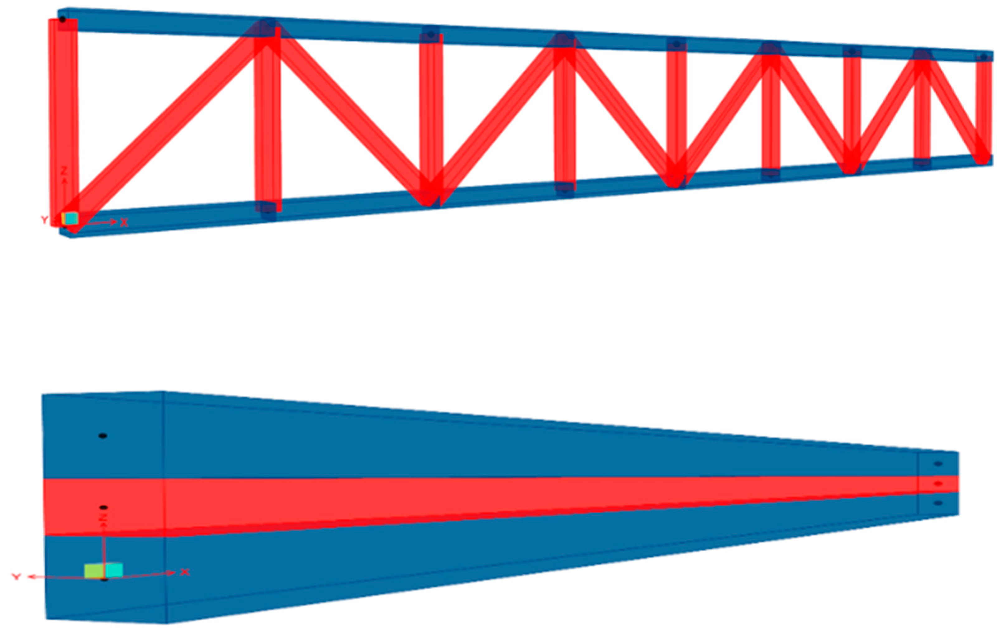
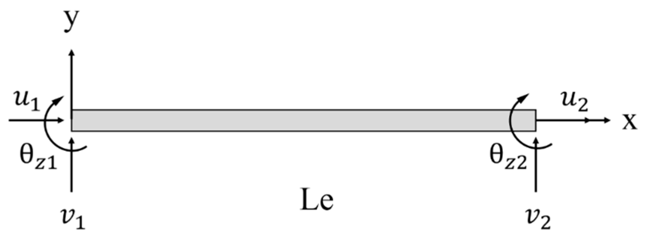
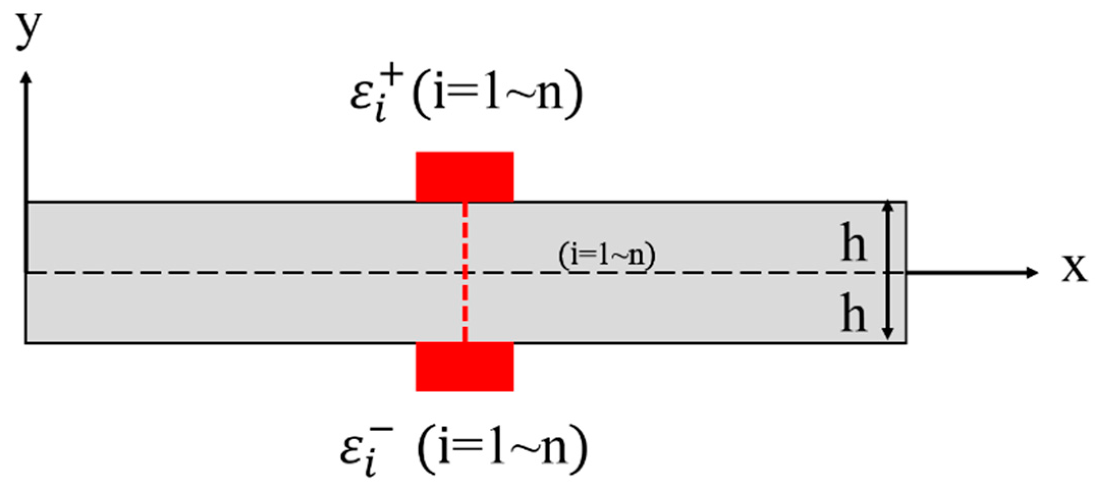
2. Inverse Finite Element Formulation of the Truss Structure
2.1. The Principle of Equivalent Stiffness
2.2. The Principle of iFEM Algorithm
3. Performance Study of the Deflection Sensor
3.1. Calibration Test
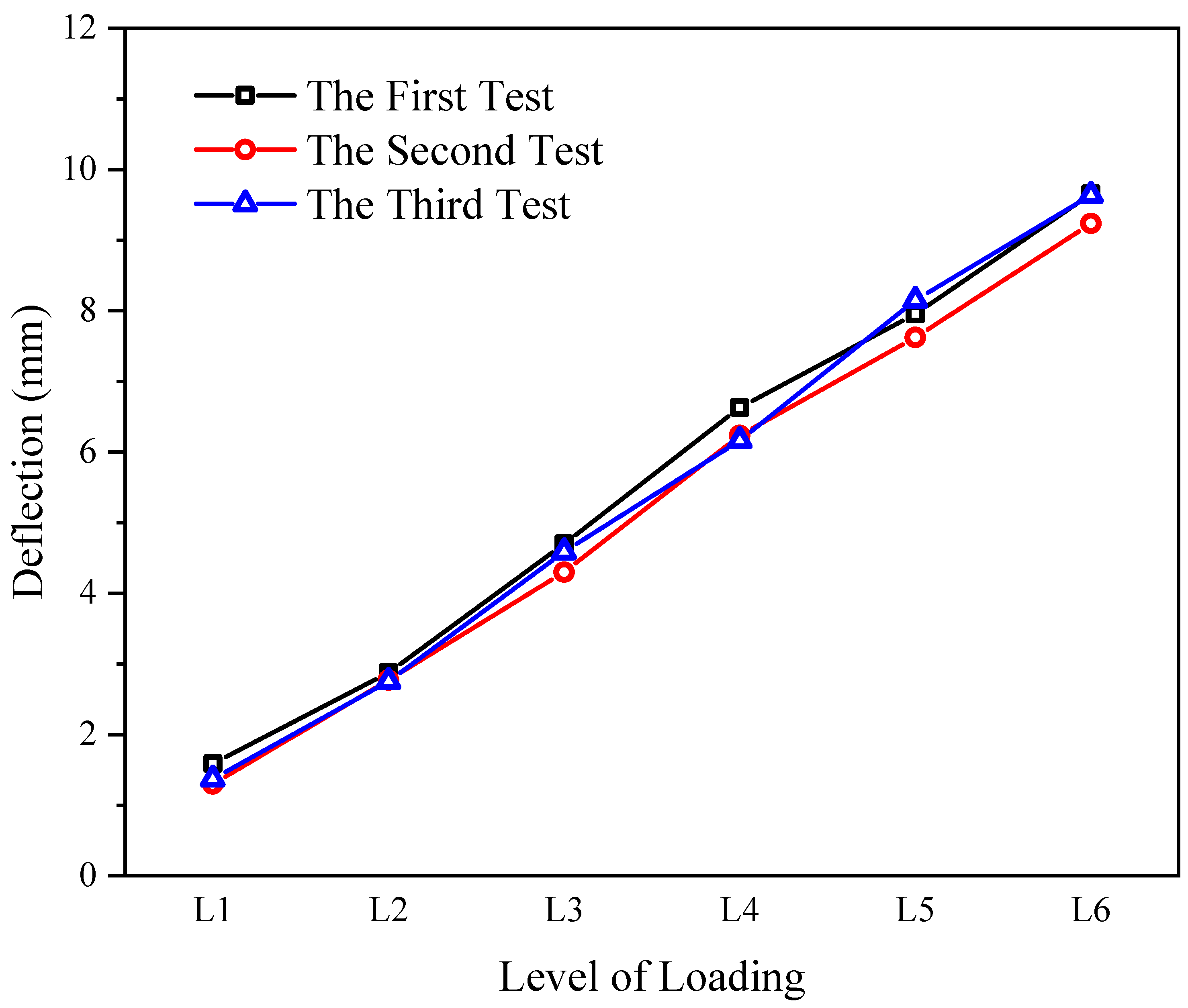
3.2. Stability Test
4. Application of the Deflection Sensor in the Truss Structure
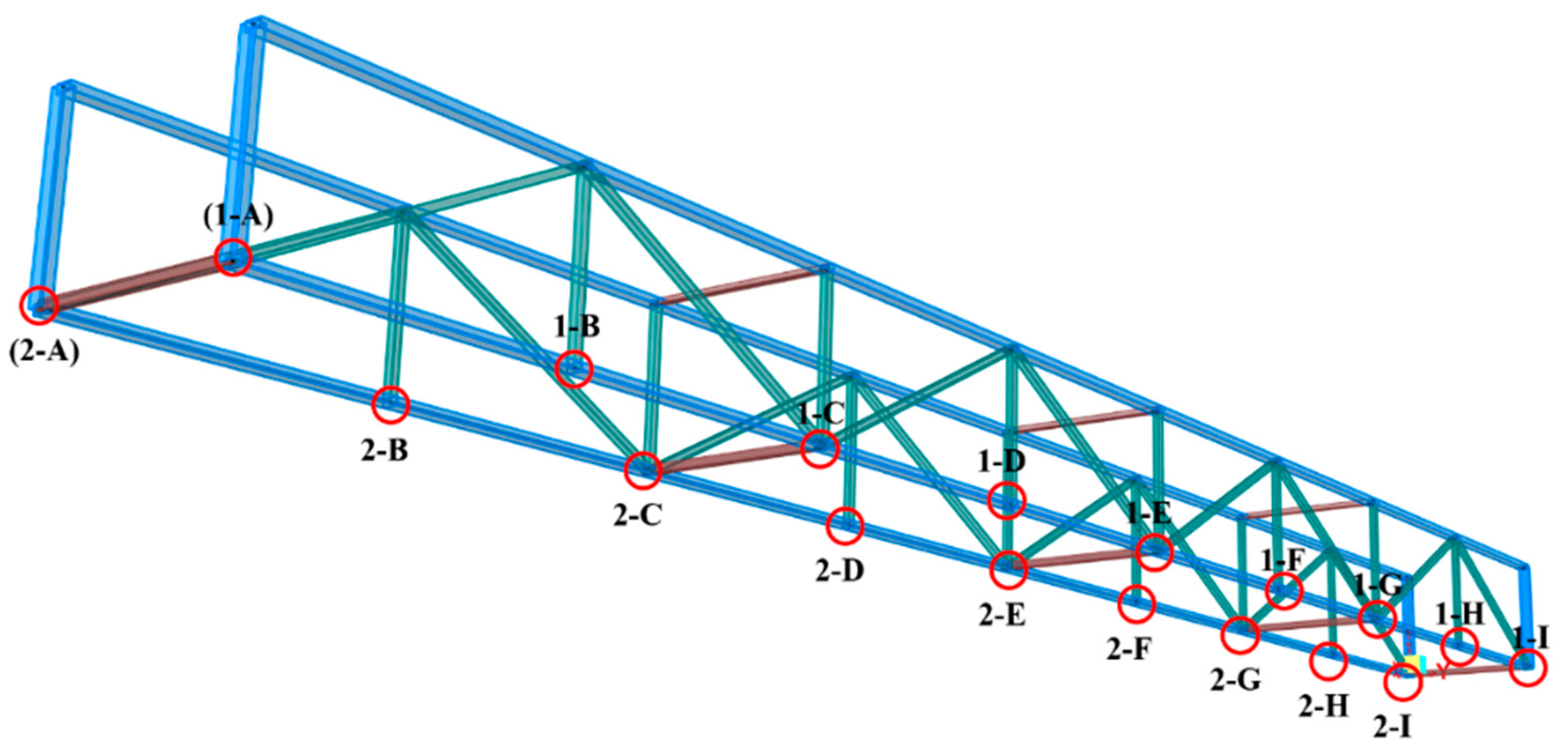
4.1. Testing Setup
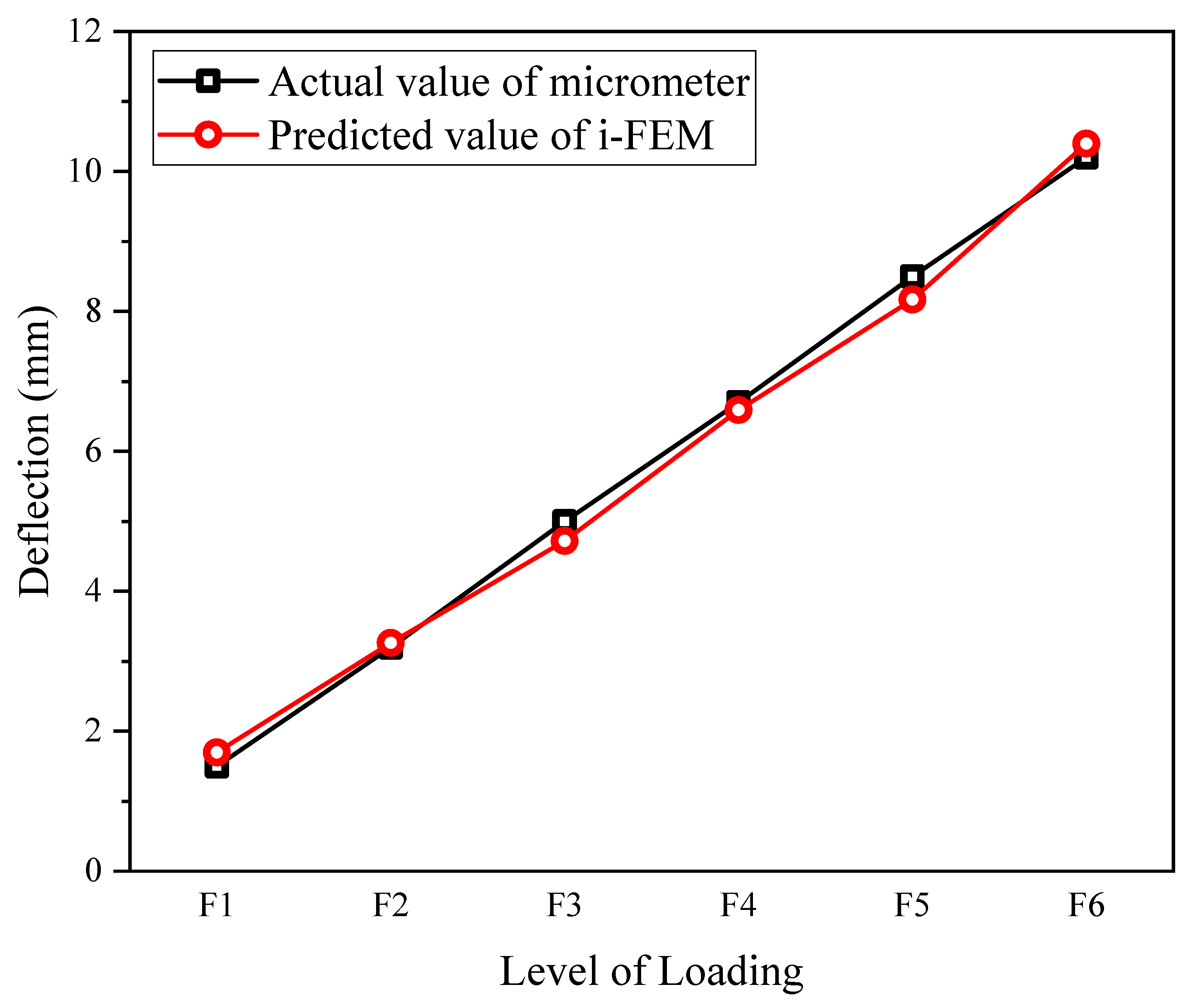
4.2. Testing Results
5. Conclusions
Author Contributions
Funding
Institutional Review Board Statement
Conflicts of Interest
References
- Li, H.-N.; Ren, L.; Jia, Z.-G.; Yi, T.-H.; Li, D.-S. State-of-the-art in structural health monitoring of large and complex civil infrastructures. J. Civ. Struct. Health Monit. 2016, 6, 3–16. [Google Scholar] [CrossRef]
- Wang, W.; Wang, X.; Hua, X.; Song, G.; Chen, Z. Vibration control of vortex-induced vibrations of a bridge deck by a single-side pounding tuned mass damper. Eng. Struct. 2018, 173, 61–75. [Google Scholar] [CrossRef]
- Yin, X.; Liu, Y.; Song, G.; Mo, Y.L. Suppression of Bridge Vibration Induced by Moving Vehicles Using Pounding Tuned Mass Dampers. J. Bridge Eng. 2018, 23. [Google Scholar] [CrossRef]
- Huo, L.; Li, C.; Jiang, T.; Li, H.-N. Feasibility Study of Steel Bar Corrosion Monitoring Using a Piezoceramic Transducer Enabled Time Reversal Method. Appl. Sci. 2018, 8, 2304. [Google Scholar] [CrossRef]
- Peng, J.; Hu, S.; Zhang, J.; Cai, C.; Li, L.-Y. Influence of cracks on chloride diffusivity in concrete: A five-phase mesoscale model approach. Constr. Build. Mater. 2019, 197, 587–596. [Google Scholar] [CrossRef]
- Peng, J.; Xiao, L.; Zhang, J.; Cai, C.; Wang, L. Flexural behavior of corroded HPS beams. Eng. Struct. 2019, 195, 274–287. [Google Scholar] [CrossRef]
- Sitton, J.D.; Story, B.A.; Zeinali, Y. Bridge Impact Detection and Classification Using Artificial Neural Networks. In Proceedings of the 11th International Workshop on Structural Health Monitoring, Stanford, CA, USA, 12–14 September 2017; pp. 1261–1267. [Google Scholar] [CrossRef]
- Song, G.; Olmi, C.; Gu, H. An overheight vehicle-bridge collision monitoring system using piezoelectric transducers. Smart Mater. Struct. 2007, 16, 462–468. [Google Scholar] [CrossRef]
- Kong, Q.; Robert, R.H.; Silva, P.; Mo, Y.L. Cyclic Crack Monitoring of a Reinforced Concrete Column under Simulated Pseudo-Dynamic Loading Using Piezoceramic-Based Smart Aggregates. Appl. Sci. 2016, 6, 341. [Google Scholar] [CrossRef]
- Zhou, L.; Zheng, Y.; Song, G.; Chen, D.; Ye, Y. Identification of the structural damage mechanism of BFRP bars reinforced concrete beams using smart transducers based on time reversal method. Constr. Build. Mater. 2019, 220, 615–627. [Google Scholar] [CrossRef]
- Bonopera, M.; Chang, K.-C.; Chen, C.-C.; Lin, T.-K.; Tullini, N. Bending tests for the structural safety assessment of space truss members. Int. J. Space Struct. 2018, 33, 138–149. [Google Scholar] [CrossRef]
- Maes, K.; Peeters, J.; Reynders, E.; Lombaert, G.; De Roeck, G. Identification of axial forces in beam members by local vibration measurements. J. Sound Vib. 2013, 332, 5417–5432. [Google Scholar] [CrossRef]
- Ren, L.; Jiang, T.; Jia, Z.-G.; Li, D.-S.; Yuan, C.-L.; Li, H.-N. Pipeline corrosion and leakage monitoring based on the distributed optical fiber sensing technology. Measurement 2018, 122, 57–65. [Google Scholar] [CrossRef]
- Li, H.N.; Li, D.S. Safety assessment, health monitoring and damage diagnosis for structures in civil engineering, Earthq. Eng. Eng. Vib. 2002, 22, 82–90. [Google Scholar] [CrossRef]
- Gherlone, M.; Cerracchio, P.; Mattone, M. Shape sensing methods: Review and experimental comparison on a wing-shaped plate. Prog. Aerosp. Sci. 2018, 99, 14–26. [Google Scholar] [CrossRef]
- Ko, W.L.; Richards, W.L.; Tran, V.T. Displacement Theories for In-Flight Deformed Shape Predictions of Aerospace Structures. NASA/TP-2007-214612. 1 October 2007. [Google Scholar]
- Bang, H.J.; Ko, S.W.; Jang, M.S.; Kim, K.I. Shape estimation and health monitoring of wind turbine tower using a FBG sensor array. In Proceedings of the 2012 IEEE International Instrumentation and Measurement Technology Conference Proceedings, Graz, Austria, 13–16 May 2012; pp. 496–500. [Google Scholar]
- Tessler, J.A. A Variational Principle for Reconstruction of Elastic Deformations in Shear Deformable Plates and Shells. NASA/TM-2003-212445. 1 August 2003. [Google Scholar]
- Tessler, A.; Spangler, J.L. A least-squares variational method for full-field reconstruction of elastic deformations in shear-deformable plates and shells. Comput. Methods Appl. Mech. Eng. 2005, 194, 327–339. [Google Scholar] [CrossRef]
- Kefal, A.; Oterkus, E. Shape Sensing of Aerospace Structures by Coupling Isogeometric Analysis and Inverse Finite Element Method. In Proceedings of the 58th AIAA/ASCE/AHS/ASC Structures, Structural Dynamics, and Materials Conference, Grapevine, TX, USA, 9–13 January 2017; pp. 1–10. [Google Scholar] [CrossRef]
- You, R.; Ren, L.; Yuan, C.; Song, G. Two-Dimensional Deformation Estimation of Beam-Like Structures Using Inverse Finite-Element Method: Theoretical Study and Experimental Validation. J. Eng. Mech. 2021, 147, 04021019. [Google Scholar] [CrossRef]


| Case Number | Loading Position | Level of Loading | Type of Loading |
|---|---|---|---|
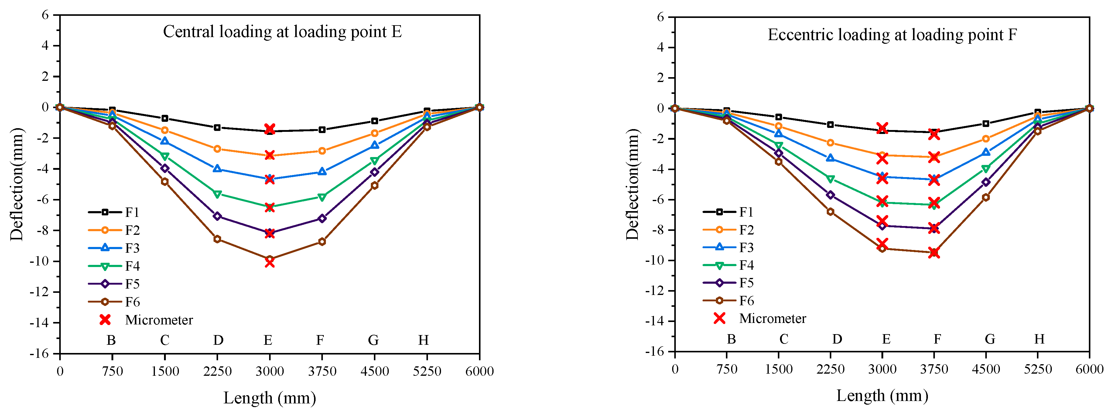
| 1 | E | F1-F6 | Central loading |
| 2 | F | F1-F6 | Eccentric loading |
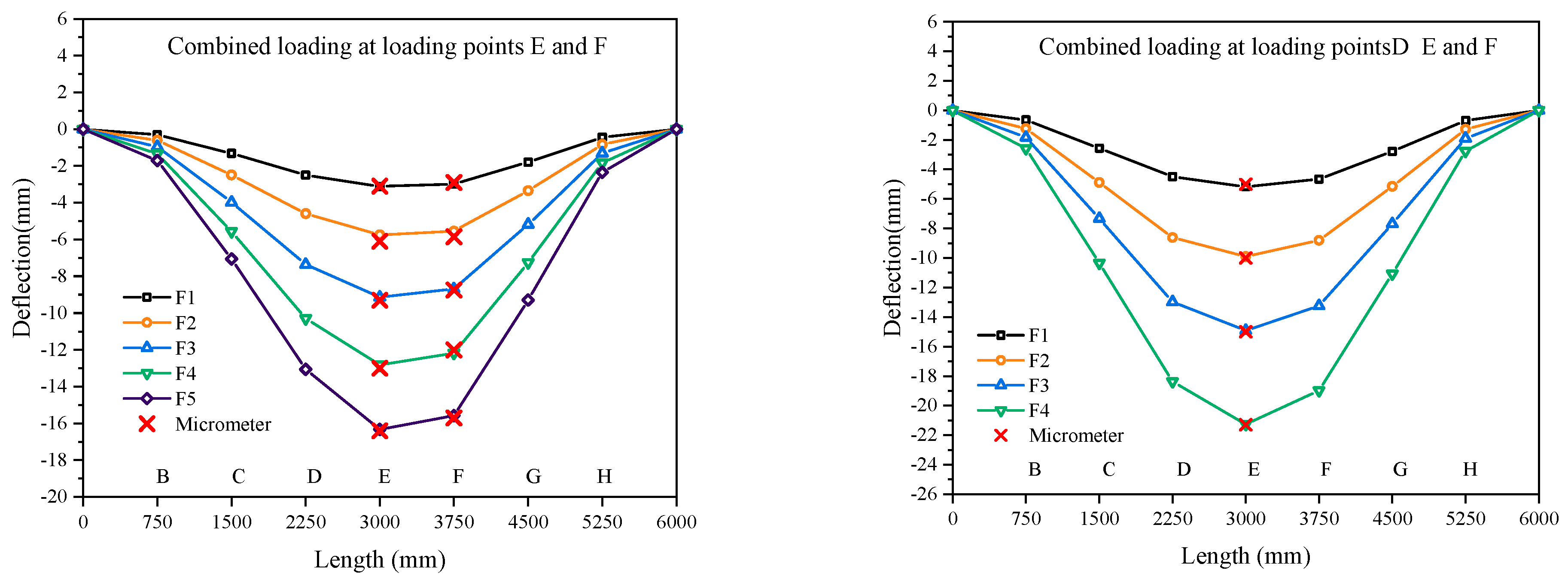
| 3 | E-F | F1-F5 | Combined loading |
| 4 | D-E-F | F1-F4 | Combined loading |
| Central loading | E Point | ||||||
| Micrometer | iFEM | Deviation | |||||
| F1 | −1.5 | −1.57 | 0.07 | ||||
| F2 | −3.2 | −3.26 | 0.06 | ||||
| F3 | −5.0 | −4.67 | 0.30 | ||||
| F4 | −6.7 | −6.47 | 0.23 | ||||
| F5 | −8.2 | −7.97 | 0.23 | ||||
| F6 | −10.2 | −10.40 | 0.20 | ||||
| Eccentric loading | E Point | F Point | |||||
| Micrometer | iFEM | Deviation | Micrometer | iFEM | Deviation | ||
| F1 | −1.3 | −1.28 | 0.01 | −1.7 | −1.57 | 0.13 | |
| F2 | −3.3 | −3.21 | 0.09 | −3.2 | −3.21 | 0.00 | |
| F3 | −4.6 | −4.91 | 0.31 | −4.7 | −4.68 | 0.03 | |
| F4 | −6.1 | −6.10 | 0.00 | −6.2 | −6.35 | 0.15 | |
| F5 | −7.4 | −7.47 | 0.06 | −7.9 | −7.90 | 0.03 | |
| F6 | −8.9 | −9.06 | 0.16 | −9.5 | −9.48 | 0.01 | |
| Combined loading– E and F | E Point | F Point | |||||
| Micrometer | iFEM | Deviation | Micrometer | iFEM | Deviation | ||
| F1 | −3.1 | −2.98 | 0.13 | −2.9 | −2.98 | 0.08 | |
| F2 | −6.1 | −6.27 | 0.17 | −5.8 | −5.54 | 0.31 | |
| F3 | −9.5 | −9.41 | 0.10 | −8.8 | −8.68 | 0.07 | |
| F4 | −13.0 | −12.42 | 0.58 | −12.0 | −12.18 | 0.18 | |
| F5 | −16.4 | −16.20 | 0.20 | −15.7 | −15.58 | 0.12 | |
| Combined loading– D, E, and F | E Point | ||||||
| Micrometer | iFEM | Deviation | |||||
| F1 | −5.1 | −4.61 | 0.49 | ||||
| F2 | −10.0 | −9.38 | 0.62 | ||||
| F3 | −14.9 | −14.35 | 0.55 | ||||
| F4 | −21.3 | −20.60 | 0.70 | ||||
Disclaimer/Publisher’s Note: The statements, opinions and data contained in all publications are solely those of the individual author(s) and contributor(s) and not of MDPI and/or the editor(s). MDPI and/or the editor(s) disclaim responsibility for any injury to people or property resulting from any ideas, methods, instructions or products referred to in the content. |
© 2023 by the authors. Licensee MDPI, Basel, Switzerland. This article is an open access article distributed under the terms and conditions of the Creative Commons Attribution (CC BY) license (https://creativecommons.org/licenses/by/4.0/).
Share and Cite
Zhang, Z.; Zheng, S.; Li, H.; Ren, L. Deflection Estimation of Truss Structures Using Inverse Finite Element Method. Sensors 2023, 23, 1716. https://doi.org/10.3390/s23031716
Zhang Z, Zheng S, Li H, Ren L. Deflection Estimation of Truss Structures Using Inverse Finite Element Method. Sensors. 2023; 23(3):1716. https://doi.org/10.3390/s23031716
Chicago/Turabian StyleZhang, Zhaobo, Shuai Zheng, Hongnan Li, and Liang Ren. 2023. "Deflection Estimation of Truss Structures Using Inverse Finite Element Method" Sensors 23, no. 3: 1716. https://doi.org/10.3390/s23031716
APA StyleZhang, Z., Zheng, S., Li, H., & Ren, L. (2023). Deflection Estimation of Truss Structures Using Inverse Finite Element Method. Sensors, 23(3), 1716. https://doi.org/10.3390/s23031716