4.1. Dual-Antenna GNSS System and Precision Factor
GNSS consists of space satellite, ground console and user receiving terminal. GNSS space satellite systems include GPS (Global Positioning System), GLONASS, GALILEO, Beidou, etc. Each system consists of several satellites in different orbits. Each satellite continuously sends signals to Earth to help complete navigation and positioning, timing and short message communication and other functions. From the perspective of positioning methods, GNSS can be divided into absolute positioning and differential positioning. Based on single-antenna GNSS, with antenna 1 as the reference station and antenna 2 as the terminal station, the coordinates of the two antennas are obtained by differential positioning method, and the baseline vector between the two antennas is solved so as to complete the heading and pitch angle measurement.
The calculation error of GNSS can be judged by three precision factors, among which
(position dilution of precision) represents the square and square root of standard deviation between longitude, latitude and height,
(vertical dilution of precision) represents the square and square root of standard deviation between longitude and latitude and
(horizontal dilution of precision) represents the standard deviation of elevation [
17].The relationship between them can be expressed as
[
18]. By discriminating the value of the three accuracy factors, the quality of the current satellite calculation can be identified. The better the quality of the solution, the smaller the error and the corresponding precision factor value will be. Combine with other methods to compensate.
4.2. Updating Algorithm of Strapdown Inertial Navigation System
The strapdown inertial navigation system is firmly connected to the carrier, and the angular velocity and specific force of the carrier are measured by collecting the data of the internal inertial measurement unit. Then, the attitude, velocity and position information of the carrier are calculated by the inertial navigation updating equation. MINS uses MEMS gyro and MEMS accelerometer devices, making it smaller and cheaper than other inertial navigation systems and allowing it to play a more important role in more areas.
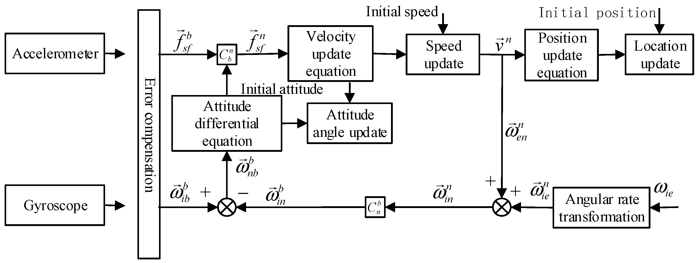
The MINS obtains carrier-specific force information from the MEMS accelerometer inside the IMU, and the MEMS gyroscope obtains carrier angular rate information. After error compensation, coordinate system change, updating equation computation and other steps, the latest navigation information of the carrier is obtained. The inertial navigation solution graph is shown in
Figure 2 below.
First, the original carrier-specific force information obtained by the accelerometer is compensated for error to eliminate the accelerometer bias and installation error, and then the vector value of the specific force in the navigation coordinate system is obtained by multiplying the compensated specific force vector by the directional cosine matrix .
Next, the velocity vector under the navigation coordinate system is obtained by substituting into the velocity update equation, and then the position coordinate quantity under the updated navigation coordinate system is obtained by substituting into the position update equation.
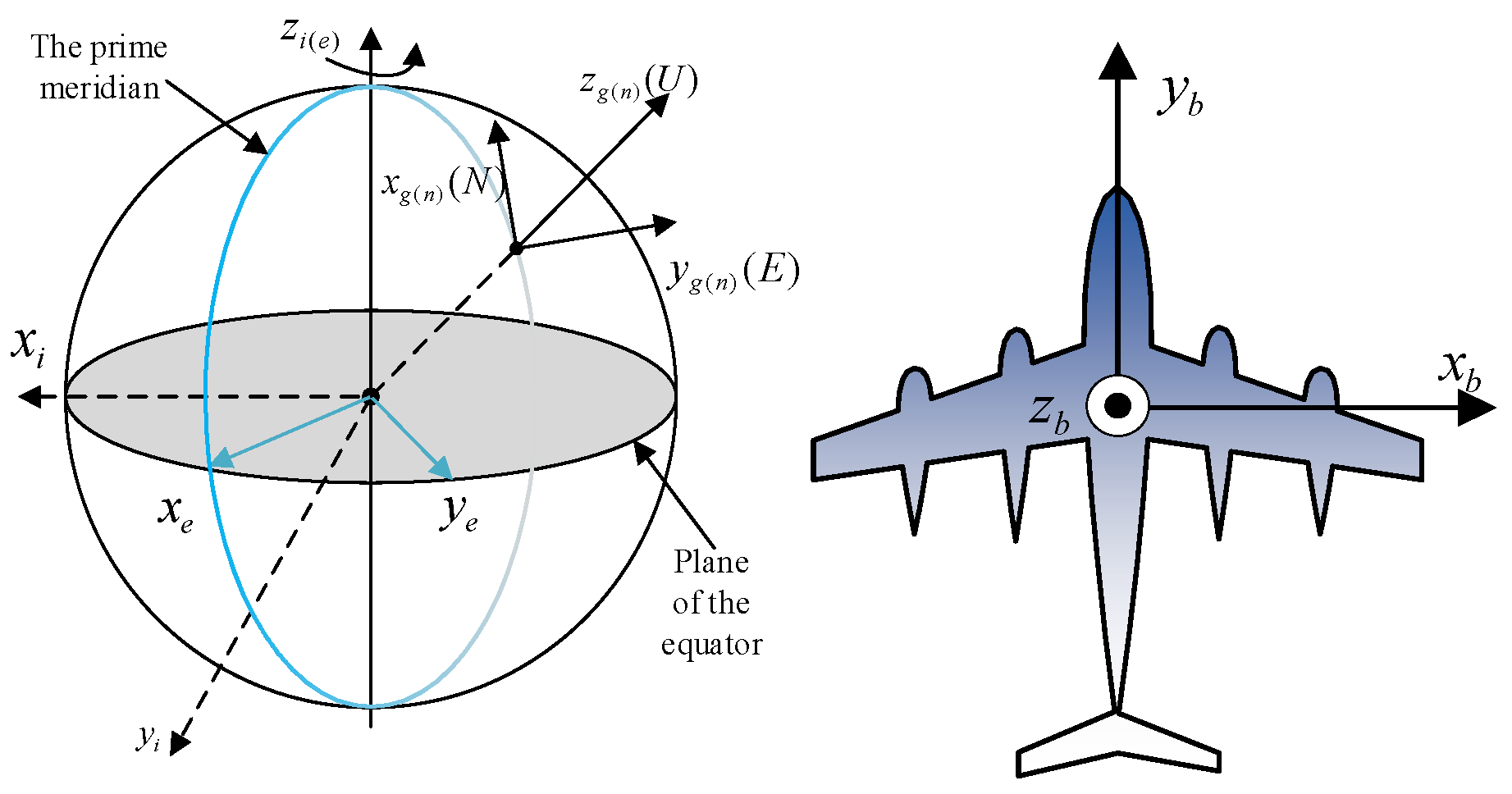
The angular rate
is obtained from the gyro data after the effects of its bias and mounting errors are removed by error compensation. Due to the motion of the carrier, the carrier will generate an angular rate
with respect to the
coordinate system under the
coordinate system, which is given by:
where
is the radius of curvature of the meridian circle,
is the radius of curvature of the prime unitary circle,
is the altitude and
is the local latitude. When the curvature of Earth is neglected as a sphere, it can be approximated as
.
The rotation rate of Earth is . Using Equation , we obtain its projection under the coordinate system. Add and to obtain the rotation angular rate of the coordinate system with respect to the I-system, and then transform the orientation cosine matrix to obtain the angular rate projection of the B-system.
Finally, the angular rate projection of the B-system with respect to the N-system in the B-system is obtained by subtracting from and substituting it into the attitude differential equation to update the equivalent cosine matrix and the attitude angle.
Due to the large noise of the MEMS gyroscope, it is difficult to perceive the angular rate variations of the system with respect to the I-system caused by the rotation of Earth and the motion of the aircraft. To simplify the calculation, the angular rate can be taken to be zero.
Inertial navigation update algorithm includes attitude update algorithm, velocity update algorithm and position update algorithm, among which accuracy of attitude update algorithm has a decisive influence on accuracy of the whole inertial navigation system.
- (1)
Attitude updating algorithm
There are three common ways to represent the attitude, which are Euler angle, direction cosine matrix and Quaternion. Euler angle is the most intuitive representation, which directly reflects the current vehicular attitude through the size of heading angle, pitch angle and roll angle. However, when the pitch angle is close to 90°, the Euler angle will be used to calculate the singular value, resulting in the phenomenon of universal joint deadlock [
19], and it is impossible to measure the full attitude. The direction cosine matrix has 9 differential equations, which requires a large amount of computation and is not conducive to the real-time performance of navigation computer. Quaternion has been widely used because it has only four elements, a small amount of computation and can overcome the influence of singular value on attitude measurement. In this paper, Quaternion will be used for attitude representation, and its expression method is as follows.
Quaternion is used to represent the relative conversion relationship between the vehicular system and the navigation system, and the Quaternion expression of the direction cosine matrix can be obtained in Equation (23).
Using Euler angles to represent the direction cosine matrix is shown below.
Euler’s angle is expressed as a Quaternion.
The Quaternion differential equation is as follows.
where
is the angular velocity of the vehicular around the
,
and
axes of the vehicular coordinate system.
When non-fixed axis rotation occurs, direct Euler angle solution will introduce rotational non-exchangeable error to affect the accuracy of solution. Therefore, an equivalent rotation vector should be introduced to reduce the impact of error on the accuracy. The differential equation of the Equivalent rotation vector is shown in Equation (27).
In order to ensure the accuracy and real-time performance of the solution, this paper adopts the algorithm of “monad sample + previous period” to calculate the equivalent rotation vector, and its formula is shown in Equation (28).
where the angle increment at the previous time is
and the angle increment at the current time is
.
By solving the above formula, the Quaternion recursive calculation formula is obtained.
where
is the updated Quaternion at time
and
is the change value of the Quaternion at time
to
.
- (1)
Velocity update algorithm
To calculate Earth’s rotation velocity
, assume that the cruising velocity of a navigable aircraft is
and its altitude is
; its maximum angular velocity of
series relative to
series is
, both of which will be submerged in the noise of MEMS gyroscope. Therefore, the simplified inertial navigation specific force equation is directly used in this paper.
The velocity renewal equation is as follows.
where
is the velocity of the vehicular under the
system at time
,
is the specific force increment output by the accelerometer during the period
to
,
is the angular velocity increment of the vehicular during the period
to
and
is the sampling period.
- (2)
Location update algorithm
Differential equations with updated positions are as follows.
4.3. Error Analysis of Strapdown Inertial Navigation System and Establishment of Error Equation and Model
The updating equations of the Jet-Link inertial guidance system are defaulted to operate the system without errors under ideal conditions. However, in actual application, measurement and operation of the inertial devices can lead to errors, which are further accumulated by the navigation algorithm, and the overall accuracy of the system will gradually decrease. For this reason, error analysis and modeling of the system are needed to reduce the impact of errors.
- (1)
Attitude error Equation
Under the assumption that there is no error in the system, the ideal direction cosine matrix is
. However, realistic rotation will have errors added to it, resulting in the actual calculated direction cosine matrix being
. That means that there is a deviation between the calculated navigation coordinate system
and the ideal navigation coordinate system
obtained from the calculation, and according to the chain multiplication rule, there is:
The equivalent rotation vector from the
system to the
system is denoted as
and referred to as the misalignment angle error. With short sampling time,
is a very small quantity and can be approximated using the equation for the relationship between equivalent rotation vector and direction cosine [
20], which is obtained as follows:
Without considering its angular rate with respect to the inertial coordinate system caused by the motion of the navigation coordinate system, there is equation
, according to which the differential equation for the direction cosine matrix in the presence of error is obtained as:
where
is the vehicular angular rate containing the error; the equation is as follows:
where
is the first-order Markov process drift of the gyroscope and
is the white noise of the gyroscope.
Differentiating the two sides of Equation (35) yields:
Associating Equations (36) and (37), the following equation can be obtained:
Substituting Equations (35)–(37) into (39), it can be obtained:
By swapping the two sides and neglecting the second-order minima in them, posture Equation (41) is obtained:
- (2)
Velocity error Equation
As with the attitude error, in the actual navigation calculation, the inclusion of various errors due to it will result in error between the velocity
obtained from the navigation calculation and the ideal velocity
. The error calculation equation is as follows:
Differentiating both sides of Equation (42), it is possible to obtain:
For ease, the simplified differential equation for the inertial conductivity ratio Equation (43) is rewritten as follows.
Without considering the error of gravity, the actual calculated differential equation for the inertia ratio force is obtained as follows.
where
where
is the first-order Markov process drift of the accelerometer and
is the white noise of the accelerometer.
The ratio differential equation obtained by using the actual calculation is subtracted from the ideally obtained ratio differential equation. Equation (45) minus (44), the two error differential equations can be obtained as:
Then, bring Equations (35) and (46) into (47), expand and neglect the second-order minima about the error; the velocity error equation is obtained:
- (3)
Position error Equation
By deviating the equations corresponding to the differential equations of latitude, longitude and altitude of Equation (33), the following equation can be obtained.
Neglecting the effect of the second-order minima in it, it is written in matrix form as follows.
- (4)
Mathematical model of gyroscope error
The main error of the gyroscope can be obtained according to Equation (37), which contains the first-order Markov process drift error of the gyroscope and the white noise random drift of the gyroscope, and the MSE of the white noise is [
21].
The mathematical model of the first-order Markov process drift error
is as follows.
where
is the Markov correlation time,
is the Markov correlation white noise with mean squared difference
. The drift error is converted to the navigation coordinate system using equation
.
- (5)
Mathematical model of accelerometer error
According to Equation (46), the main error of the accelerometer can be obtained, which contains the first-order Markov process drift error of the accelerometer, the white noise random drift of the accelerometer and the MSE of the white noise .
The mathematical model of the first-order Markov process drift error
is as follows.
In the same mathematical model as the gyroscope error, in the above equation is the Markov correlation time and is the Markov correlation white noise with mean squared deviation . The drift error is converted to the navigation coordinate system using equation .
4.4. An Initial Alignment Algorithm of Dual-Antenna GNSS and Magnetometer-Assisted MINS
Before normal operation of the Jet-Link inertial guidance system, an initial alignment is first required to determine the initial position, velocity, attitude and other information of the vehicle in the current state. Among them, initial alignment of vehicular heading is particularly important and is the difficult part of the alignment phase [
22]. A high-accuracy inertial guidance system can be sensitive to the rotation of Earth and achieve the heading alignment function without other external auxiliary information. However, the MEMS IMU is noisy and insensitive and cannot measure the angular rate of Earth’s rotation; for this reason, this paper will use magnetometer and dual-antenna GNSS for initial heading angle alignment. In this paper, the initial velocity is defaulted to zero, and the positioning output of GNSS after stable operation is used as the initial position.
- (1)
The initial attitude alignment is based on angular velocity meter and magnetometer
The vector measured by the accelerometer in the vehicular coordinate system is
, and its projection in the navigation coordinate system is
. In the static case, there is the specific force equation
, which is
, expanded into the following component form.
By solving the above equation, it can be obtained:
The equations for the pitch angle
and the cross-roll angle
can be obtained by combining Equation (20) as [
23]:
The magnetometer is solidly connected to the vehicular, and its coordinate system is the vehicular coordinate system
. The output of the magnetometer in the
system is
. When the vehicular coordinate system
coincides with the magnetic geographic coordinate system
, the magnitude of the magnetic field measured by the magnetometer at this time is
. According to the formula and Equation (20), the following can be obtained:
Further, the heading angle can be obtained as:
- (2)
Alignment algorithm of initial heading angle and pitch angle based on dual-antenna GNSS
GNSS has the global positioning function, which can realize the all-weather accurate position navigation function. The positioning data provided by GNSS is also the main basis for the initial position alignment of the system. Dual-antenna GNSS can assist in determining the heading angle and pitch angle. In this paper, dual-antenna GNSS is mainly used to measure the heading angle and pitch angle when the satellite signal is excellent.
Dual-antenna GNSS has two satellite signal receiving antennas, the main antenna ANT1 and the secondary antenna ANT2, which are mounted on the longitudinal axis of the aircraft, and the baseline distance between the two antennas is .
First, obtain the position coordinates
and
of ANT1 and ANT2 antennas, respectively, then subtract them to obtain the difference of position coordinates
of the two antennas, where
is the difference of the distance between the two antennas in the direction of east, north and sky, respectively, then substitute the above values into the following formula to obtain the heading angle
and pitch angle
.
At the time of antenna installation, the distance between the two antennas can be measured exactly, and, at the same time, based on the position coordinates provided by the two antennas, the calculated positioning distance of the antennas can be obtained. By calculating the difference between and , the accuracy of the satellite positioning signal can be judged, and thus its credibility. The coordinates of the midpoint of the line connecting the two antennas are used as the vehicular coordinates of the aircraft so that they are used as the data for the initial alignment of the position.
4.5. Aircraft Flight State Recognition and Attitude Compensation
In different terrain environments, the navigable aircraft will face various environmental disturbances, and there may also be a satellite signal failure; when the integrated navigation system loses the update of the satellite measurement signal, the attitude angle may gradually drift, resulting in a gradual increase in the error angle, affecting the attitude accuracy of the navigation system. For this reason, an aircraft flight state identification and compensation procedure is added to use the IMU raw data for flight state identification in the case of satellite signal failure and to use the transverse roll and pitch obtained by accelerometer and the heading angle obtained by magnetometer for the quantitative update in the low maneuvering flight state to improve the attitude accuracy of the system and ensure the navigation safety of the aircraft [
24].
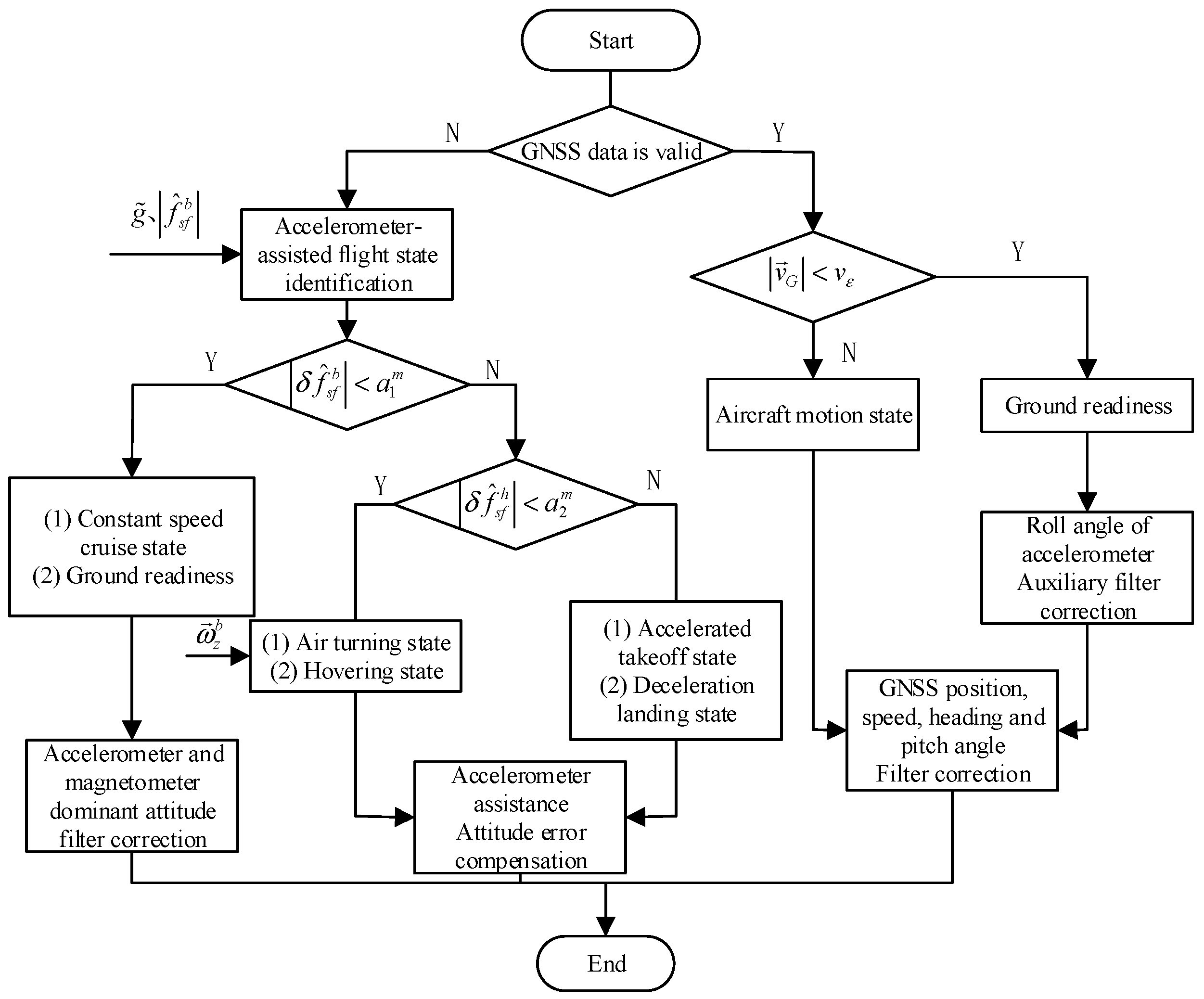
This is shown in
Figure 3 below, which shows a flowchart of the aircraft’s flight state identification and navigation correction data selection method by the navigation system.
In the static alignment phase of the through aircraft, the local reference gravitational acceleration
is found using Equations (59) and (60).
As GNSS system updates at 1 Hz, the data measurement update frequency of the system is 1 Hz. When the data sent by GNSS are received, they are parsed to judge the validity of the content, and, if the GNSS data are valid and available, they are used as the basis for judging the flight status of the aircraft according to the velocity of satellite decoding.
When ( is the velocity threshold parameter, the value is taken based on the velocity measurement noise of GNSS), the aircraft is judged to be in the ground-ready state. At this time, the heading, pitch, velocity and position information provided by GNSS are used for filtering correction, and the accelerometer is used for correction of the cross-roll angle in integration with Equation (36). When , the aircraft is judged to be in the motion state, and, at this time, the filtering correction is made entirely using the heading, pitch, velocity and position information provided by GNSS, and no correction is made for the traverse angle.
When the GNSS data are invalid, the accelerometer is used for flight mode discrimination. According to Equation (60), the accelerometer output
at moment
is obtained. When
(
is the threshold parameter; its value depends on the specific noise level setting of the environment where the navigation system is located), the aircraft is judged to be in steady state; at this time, the aircraft is in uniform cruise state or ground stationary state; this stage can use the accelerometer for attitude measurement correction.
When , the output of the horizontal biaxial accelerometer is calculated to determine the specific flight status, and the determination method is as follows.
- (1)
When ( is another threshold parameter based on the specific value of the horizontal accelerometer noise), integrated with the gyroscope data to determine, the aircraft may be in a turning state or circling state.
- (2)
When , the aircraft has a large maneuvering state and is in the takeoff or landing phase, and the accelerometer can be used to compensate for the error and reduce the error of attitude angle in this phase.


