1. Introduction
With the depletion of coal resources in the eastern mining areas and the intensification of the contradiction between resources and the environment in central mining areas, China’s coal production capacity is gradually being transferred to the western region [
1]. The western mining area has a variety of landforms. Affected by surface gullies, it is a typical gully landform [
2,
3]. Compared to the general shallow buried coal seam [
4], due to the influence of the surface gully, the mining of the working face is generally faced with the problems of mine stress concentration, strong mine pressure manifestation, and support difficulties, which seriously affect the safe and efficient operation of the mine [
5].
At present, experts and scholars have carried out some research on the law of the ground pressure behavior of the working face of shallow coal seams through surface valley mining. Wang et al. [
6] analyzed the characteristics of the first roof fracture and established a mechanical model of the roof structure during the initial and periodic fracture processes. They revealed the mechanism of sliding and rotational instability of the roof structure. Liu et al. [
7] used physical and numerical simulation methods to reveal that the lack of key strata in the process of overlying rock movement during valley terrain is crucial for the mining pressure of fully mechanized mining faces. Yi et al. [
8] elucidated the spatiotemporal evolution law of overburden movement caused by shallow, fully mechanized top coal caving and high-strength mining through similar simulation experiments, revealing the movement mode of overburden. This research shows that in the mining process of the working face in a shallow coal seam, the pressure intensity and pressure step are obviously different due to the influence of the surface gully, but the research on the influence of the stability of the mountain structure on the pressure of the working face is less extensive, meaning that it needs further research.
The similar physical model experiment is one of the most important means of studying the movement of overlying strata and the strata behavior of the working face [
9,
10]. Traditional monitoring [
11,
12,
13] instruments for overburdening deformation include the total station, dial indicator, strain gauge, etc. Most instruments can only monitor the surface deformation of the model, but they cannot monitor the internal deformation of the model. Moreover, the monitoring instruments mostly perform point monitoring, the layout of measuring points is cumbersome, and the sensitivity is low. With the development of optical fiber sensing technology, distributed optical fiber technology based on BOTDA is widely used in similar physical model experiments for the continuous monitoring of overlying rock deformation due to their advantages of high precision, high sensitivity, high reliability, simple layout, and distributed monitoring [
14,
15,
16]. Chai et al. [
17] proposed a new method to monitor the deformation of key layers of the overburden and, thus, characterize the pressure in the extraction zone using BOTDA technology. Piao et al. [
18] used BOTDA technology to study the strain distribution and motion characteristics of the strata under reamer-pillar mining through similarity simulation experiments, analyzed the stability of the remaining coal pillars in the mining area, and obtained the contour map of the strata strain through calculation. Zhang et al. [
19] used a distributed fiber optic sensing technique based on BOTDA to quantitatively access the deformation behavior of overburden rocks from a similar physical model experiment. Many results show that the distributed optical fiber sensing technology based on BOTDA can better characterize the deformation characteristics of overlying rock and the pressure law of the working face.
In this paper, BOTDA technology is applied to the similar physical model experiment, and the DIC technology is combined to monitor the deformation and the motion characteristics of the surface and interior of the model overburden. The motion characteristics of the overburden rock and the law of ground pressure behavior of the working face in a shallow coal seam are comprehensively analyzed when the working face passes through the surface valley. It has referential significance for the mining of working faces under similar conditions.
2. Engineering Geology and Production Conditions
Baijigou coal mine is located in the north of the Rujigou mining area in the middle of the Helan mountains. At present, the coal mine mainly mines a 2
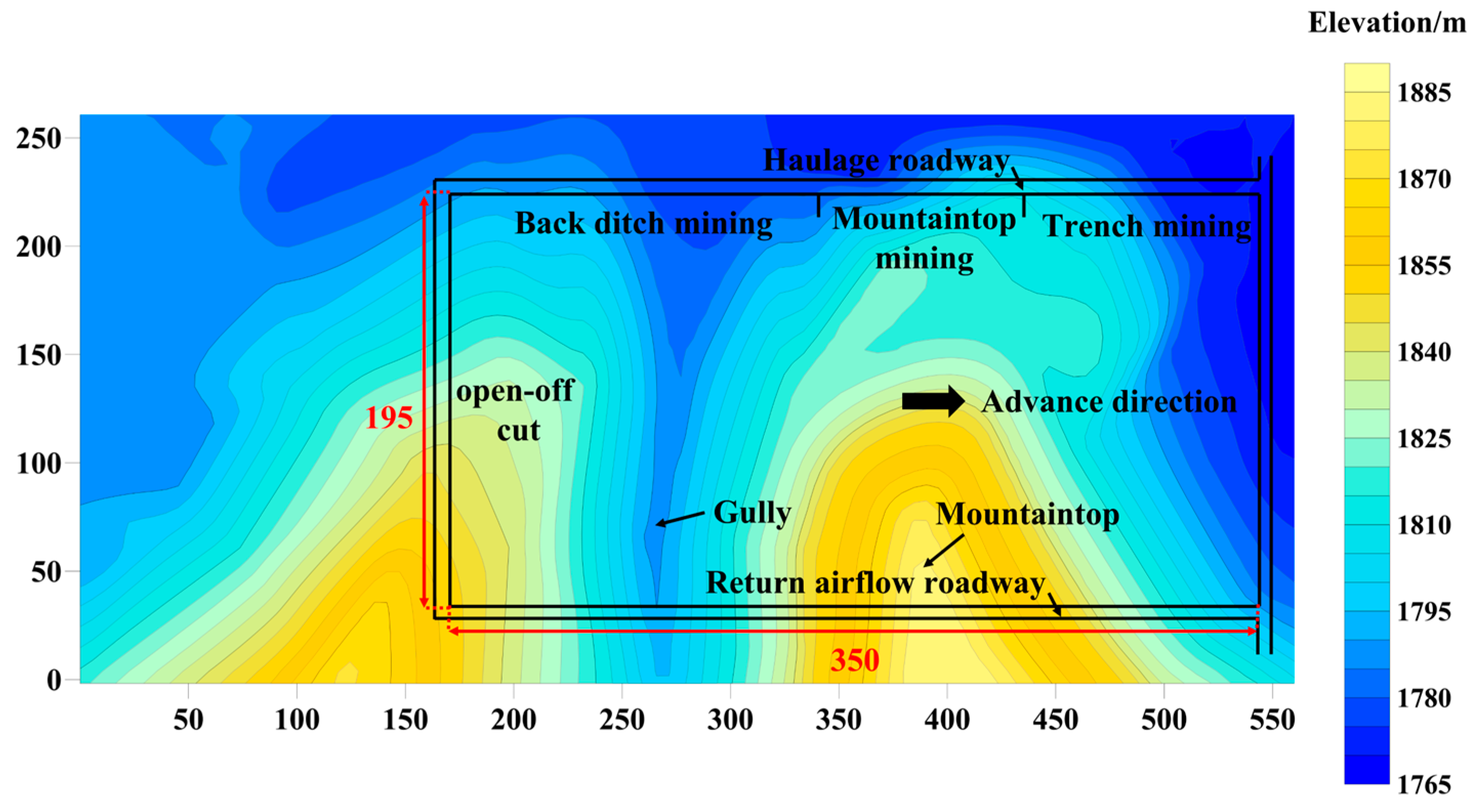
−3 coal seam, with an average thickness of 13.93 m. The mining method is layered mining, and the mining thickness of this layer is 3.0 m. The dip angle of the coal seam is between 4° and 9°, with an average angle of 6°. The relative elevation difference of the surface gullies is about 150.0 m, and the slope of the mountain is between 45° and 75°. The type of coal mining technology is the comprehensive mechanized coal mining technology. The 010204 working face is located in the southern mining area of Baijigou coal mine. The strike length of the working face is 350.0 m, and the dip length is 195.0 m. The characteristics of surface gullies and roadway layout of the 010204 working face are shown in
Figure 1.
The immediate roof of the 010204 working face is a gray–black thin-layer siltstone. The thickness of the rock layer is between 1.6 m and 6.6 m, and the average thickness of the rock layer is 4.1 m. The main roof is gray–white thick bedded coarse sandstone with an average thickness of 30.0 m. The direct bottom is siltstone with an average thickness of 0.7 m. The old bottom is dark gray thin bedded siltstone with an average thickness of 23.1 m.
3. Similar Physical Model Experiment
3.1. Physical Model Design
A similar material model experiment is an effective method for studying the laws of overlying rock failure and working face weighting, which builds a physical model based on the principle of similarity and restores the mining process. The plane model frame with a geometric size of 5.0 × 0.2 × 2.0 m is selected for the similar physical model experiment. Based on the geological conditions of Baijigou coal mine and the size of the experimental model frame, it is determined that when the geometric similarity ratio
(
lp is the prototype size on site,
lm is the model size in the laboratory), the height of the model is appropriate. The average density of the formation is
= 2.5 g/cm
3, and the density of similar materials is
= 1.6 g/cm
3, while the bulk density similarity ratio is
. The stress affinity constant is
, and the time similarity ratio is
. When the thickness of the single rock layer of the similar physical model is less than 1.0 cm, it is adverse to the building of the model. Therefore, the model rock layer is appropriately adjusted without affecting the experiment (see
Table 1 for the laying layer of the model and the ratio of similar materials).
Based on the actual terrain conditions and geometric similarity ratio, the shape of the model is cut during air-drying. In order to better distinguish the different mining stages in the mining process of the working face, the shape of the surface mountain is simplified and designed as an isosceles trapezoid. The length of the upper line of the isosceles trapezoid mountain is 20.0 cm, the length of the lower line is 236.8 cm, and the height is 108.4 cm. The bottom of the slope on the left side of the mountain is 24.6 cm away from the bottom floor of the model and 27.7 cm away from the left boundary of the model, and the angle of the bottom angle is 45°. The physical model is shown in
Figure 2.
3.2. Monitoring System Layout
The monitoring system includes the BOTDA optical fiber monitoring system, the DIC digital speckle monitoring system, and the stress monitoring system of the top and bottom of the working face. The monitoring system achieves the monitoring of the changes in stress, as well as strain and displacement on the surface and inside the model.
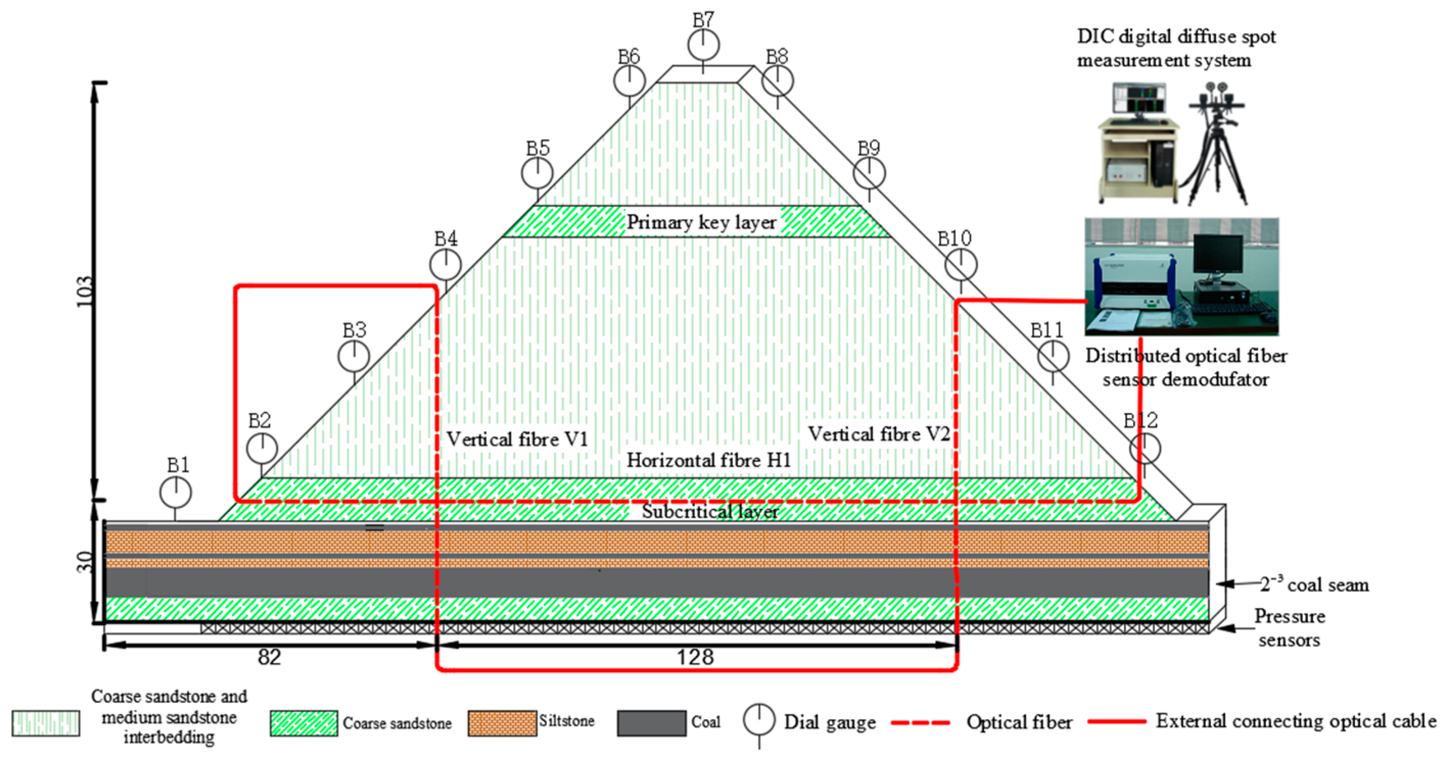
Before laying similar materials on the model, three distributed optical fibers are embedded inside the model, including two vertical optical fibers and one horizontal optical fiber. The vertical optical fibers of V1 and V2 are 82.0 cm and 210.0 cm away from the left boundary of the model, respectively. The horizontal optical fiber H1 is located in the middle of the subcritical layer of the model, and H1 is 30.0 cm away from the bottom of the model. When the BOTDA monitoring system collects the data, the optical fibers need to form a closed loop, meaning that the three optical fibers are fused with each other. The upper side of the vertical optical fiber V2 is connected to the pump light input end of the optical fiber monitoring equipment, and the right side of the horizontal optical fiber H1 is connected to the detection light output end of the optical fiber monitoring equipment. The red dotted line is the optical fiber buried inside the model, and the red solid line is the external connecting line. The experiment monitoring system deployment is shown in
Figure 3.
BOTDA optical fiber sensing technology is based on the principle of Brillouin scattering, using the effect of stimulated Brillouin scattering to obtain the Brillouin frequency shift inside the optical fiber based on the influence of external strain or temperature changes [
20]. The Brillouin frequency shift is related to the external strain and ambient temperature, as shown in Equations (1) and (2).
where
is the Brillouin frequency shift change,
is the Brillouin temperature coefficient,
is the strain calibration parameter,
is the difference in temperature change, and
is the difference in the strain change.
As the model experiment is carried out indoors, the indoor temperature change is small, and the temperature change range is between −2 °C and 2 °C. When the temperature change is less than 5 °C, the Brillouin frequency shift caused by temperature can be ignored. Therefore, the change in Brillouin frequency shift during the experiment is only related to the change in external strain. The BOTDA sensing technology is shown in
Figure 4.
The BOTDA monitoring system used in the experiment is the NBX-6055 Brillouin Time Domain Stress Analyzer produced by Neubrex Company, Kobe, Japan. Its monitoring parameters are set as a 5.0 cm spatial resolution, a 1.0 cm sampling interval, and 216 averaging times. The output probe power is 0 dBm, the output pump power is 30 dBm, and the frequency range is set from 10.60 GHz to 11.00 GHz. The distributed optical fiber used in the experiment is a 2.0 mm diameter single-mode polyurethane tight sleeve optical fiber. The elastic modulus, shear modulus, and density of the optical fiber are 300.0 kPa, 3.3 kPa, and 25.0 g/cm3, respectively. The strain calibration parameter C2 of the optical fiber is 0.05 MHz/10−6.
3.3. Experiment Steps
The width of the boundary coal pillar on both sides of the working face is 8.0 cm, and the mining height of the working face is 3.0 cm. The cut length is 10.0 cm. The working face is excavated from left to right, and the excavation distance is 3.0 cm each time. The working face has been excavated 82 times in total, and the cumulative mining distance is 256.0 cm. During the excavation of the working face, the back ditch mining stage, the peak mining stage, and the trench mining stage are successively passed. The mining distance of back ditch mining is 0.0 cm to 127.0 cm, that of mountaintop mining is 127.0 cm to 148.0 cm, and that of trench mining is 148.0 cm to 256.0 cm. After each excavation of the working face, the experiment personnel first need to wait for the overburden to be fully stable, and then they collect data from each monitoring system and, finally, carry out the next excavation after data collection.
5. Analysis of Results
5.1. Fibre Optic Characterization of Critical Layer Breakage Patterns
- (1)
Back ditch mining stage
As shown in
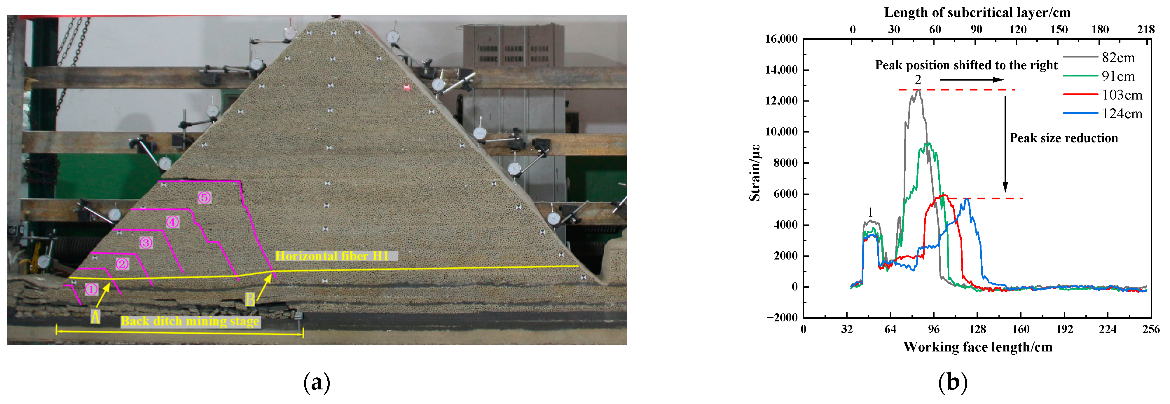
Figure 11, when the working face is advanced to 52.0 cm, the subcritical layer is broken for the first time. Mining fissures developed to the surface, forming an irregular trapezoidal rock block number ①. Due to the lack of horizontal binding force on the free side of the slope, rock block of number ① overturned to the left and sank. The strain curve of the horizontal fiber H1 produces a positive No. 1 peak strain, which reaches 4191 µε. When the working face is advanced to 82.0 cm, the subcritical layer is broken again. The high irregular trapezoidal rock block of number 3 has generated and overturned to the left, and the rock block of number 3 and the low rock block of number ② occluded each other. To a certain extent, it prevented the overturning of rock blocks of numbers ① and ②, as well as the synchronous sinking and compaction of rock blocks of numbers ① and ②. The strain curve of horizontal optical fiber H1 changes from a single peak to a double peak under the influence of the rock block of number ③. The No. 1 peak on the left side of the strain curve slightly increased to 4231 µε, and the No. 2 peak on the right side reached 12,700 µε. The peak value 2 is located 4.7 cm behind the working face, corresponding to the position of the longitudinal crack of the rock block of number ③. The sudden increase in the peak of the strain curve is a manifestation of the breaking of the subcritical layer.
As shown in
Figure 12, the subcritical layer breaks periodically as the working face advances. The mining-induced fractures are continuously developed to a high position, and irregular trapezoidal rock blocks are generated periodically. When the high-level “trapezoid” rock block is generated, the low-level fracture will gradually close, and the overturning degree of the low-level rock block will be weakened and gradually stabilized. The extent and location of the No. 1 peak strain are basically unchanged. The position of the No. 2 peak strain moves forward to the right with the advance of the working face, and the peak value gradually decreases and tends to be stable. While the working face was advancing from 82.0 cm to 124.0 cm, the No. 2 peak strain continuously decreased and remained stable after decreasing from 9294 µε to 5693 µε. The strain curve of the optical fiber in the back ditch mining stage shows that the horizontal optical fiber can monitor the breaking position of the subcritical layer. The peak strain will migrate to the right with the periodic breaking of the subcritical layer. The position of peak strain reflects the breaking position of the subcritical layer.
- (2)
Mountaintop mining stage
As shown in
Figure 13a–c, during the working face advance from 127.0 cm to 139.0 cm, the position of the No. 2 peak of the optical fiber shifts to the left, and the peak strain gradually decreases. The peak strain decreased from 5694 µε to 4083 µε. The strain curve has a wavelet peak at 53.3 cm in front of the working face, and the peak strain is 356 µε. At this time, the mining fissures in the upper part of rock block number ⑤ are gradually closed, and the mountain has a tendency to deflect to the left. The cracks at the bottom of the slope mined toward the trench are generated. Compared to the strain nephogram of DIC, the strain at the mining fracture of back ditch mining gradually decreases. The local strain increases at the bottom of the trench mining slope. The strain of DIC has the same trend as the strain curve of the optical fiber. The correctness of optical fiber sensing is further verified.
As shown in
Figure 13d–f, when the working face advances to 142.0 cm, the strain curve of the optical fiber adds two new peaks on the original basis. The No. 3 peak and No. 4 peak are 25.4 cm and 56.2 cm ahead of the working face, and the corresponding peak strains are 9593 µε and 2140 µε, respectively. The advanced tension crack is generated, and the crack develops on the surface of the trench mining slope. The working face is pressurized for the 8th cycle. The mountain deflected to the left and sank, resulting in the “imbalance” of the mountain. Compared to the strain nephogram of DIC, the strain decreases at the mining fracture of back ditch mining and increases at the advanced tension fracture. The above analysis shows that the horizontal optical fiber can monitor the migration trend of the mountain. The shift and decrease in the peak of the optical fiber strain curve is the precursor of the “imbalance” of the mountain.
- (3)
Trench mining stage
As shown in
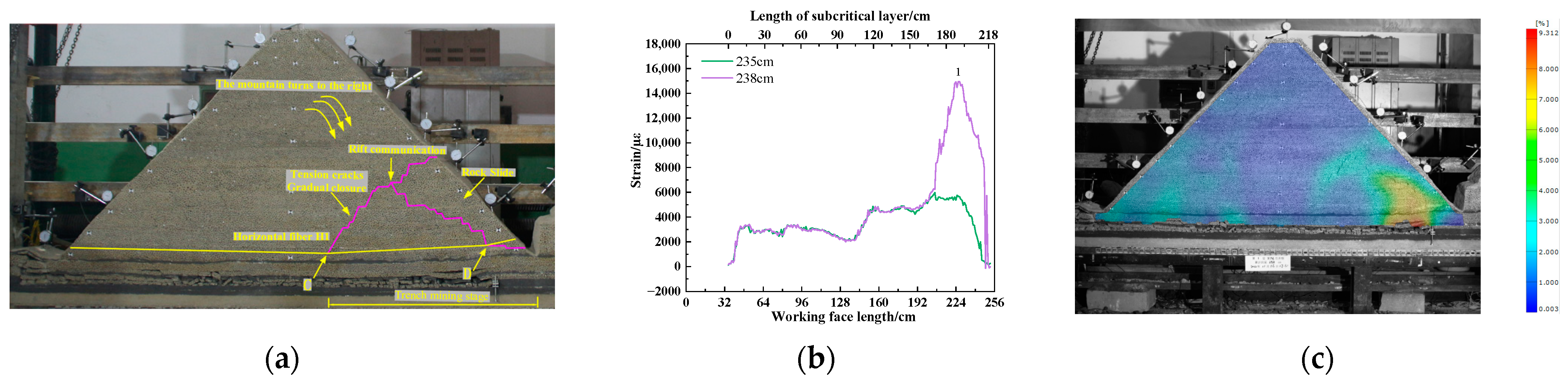
Figure 14, while the working face was advancing from 151.0 cm to 235.0 cm, the mountain began to turn and sink to the right. The tension crack gradually closes, and the overlying rock bends, breaks, and collapses from bottom to top. The overall tension degree of the horizontal optical fiber H1 gradually approaches the same trend, and the strain curve of the optical fiber presents a “saddle” shape. When the working face is pushed to 238.0 cm, the subcritical layer is broken, and the working face is pressurized for the 14th cycle. The longitudinal crack development is connected to the advance tension crack, and the sliding phenomenon occurs at the slope bottom of the trench mining. The horizontal optical fiber H1 is affected by the tensile stress at point D, and there is an obvious No. 1 peak. The peak of the fiber strain curve is 14,897 µε. The peak strain of the fiber increases by 159.2% when the working face advances to 238.0 cm compared to when it advances to 235.0 cm. The strain change corresponding to DIC also has the same phenomenon, and there is a sudden increase in strain at the slope slip.
5.2. Vertical Fiber Optic Frequency Shift Change to Pressure Characterization
When the working face is mined, the original rock stress of the overlying rock is redistributed. According to the definition of optic fiber frequency shift variation in the document [
21], the size of the optic fiber frequency shift variation is used to characterize whether or not incoming pressure is occurring at the working face. The definition of fiber frequency shift variation is
where
n is the total number of sampling points for effective monitoring distance of the optical fiber,
j is the number of working face excavations,
is the absolute value of the frequency shift at a sampling point of the optical fiber, and
is the variation degree of the optical fiber frequency shift of the jth excavation of the working face.
When the fiber frequency shift variation is more than 20 MHz, it is considered that the first pressure or cycle pressure occurs on the roof of the working face. When the fiber frequency shift variation is more than 60 MHz, it is considered that the roof pressure of the working face is intense.
The contrast information between the variation in the optical fiber frequency shift of vertical optical fiber and the working resistance of the support on the roof of the working face is shown in
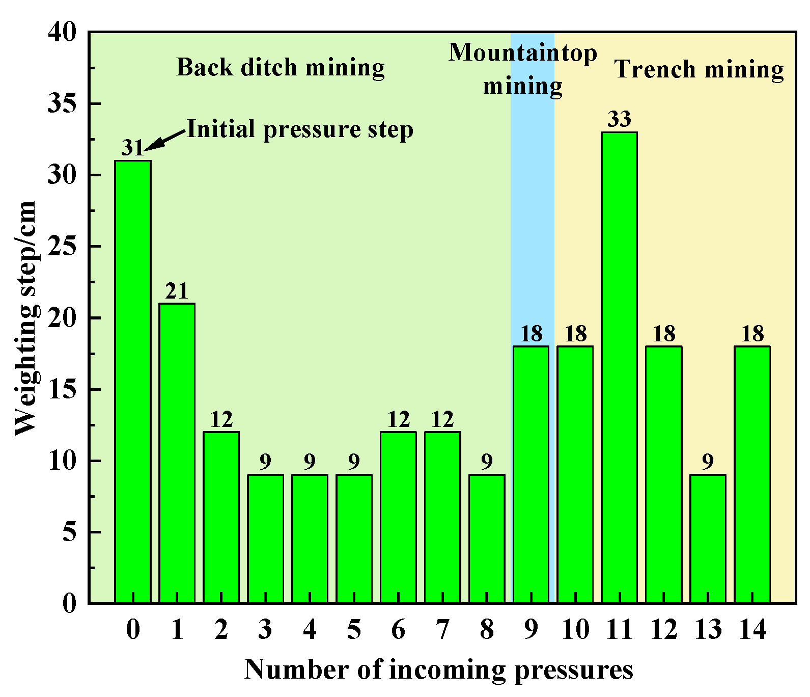
Figure 15. In the mining process of the working face, there are 15 peaks of optical fiber frequency shift, which are 31.0 cm, 52.0 cm, 64.0 cm, 73.0 cm, 82.0 cm, 91.0 cm, 103 cm, 112.0 cm, 124.0 cm, 142.0 cm, 160.0 cm, 193.0 cm, 211.0 cm, 220.0 cm, and 238.0 cm, respectively. The characterization of the pressure on the optical fiber is consistent with the pressure on the working face in the experiment, which further shows that the frequency shift variation in the optical fiber can better reflect the pressure on the working face.
The experiment shows that the initial pressure step of the working face is 31.0 cm. The average periodic weighting step in the back ditch mining stage is 11.6 cm. The average periodic weighting step in the mountaintop mining stage is 18.0 cm. The average periodic weighting step in the trench mining stage is 19.2 cm. The average periodic weighting steps of mountaintop mining and trench mining increased by 55.2% and 65.5%, respectively, compared to the average periodic weighting step of back ditch mining. The periodic weighting step of the working face is characterized by “small periodic weighting step of back ditch mining and large periodic weighting step of other stages”, as shown in
Figure 16.
According to the experiment phenomenon and the pressure situation of the working face, the mine pressure behavior law of the working face passing through the surface valley is obvious in stages. The weighting characteristics are as follows: the weighting is frequent in the back ditch mining stage, and the dynamic mine pressure is obvious. The mine pressure behavior in the mountaintop mining stage and the trench mining stage is relatively mild, but the mine pressure behavior in the working face is strong when mountain deflection and slope slip occur. The phased characteristics of the strata behavior law of the working face show that the stability of the mountain structure has a significant impact on the periodic weighting of the working face.
5.3. Horizontal Optical Fiber Characterization of Mountain Stability
We extract the peak point of the strain curve of the horizontal optical fiber H1 in
Figure 11,
Figure 12,
Figure 13 and
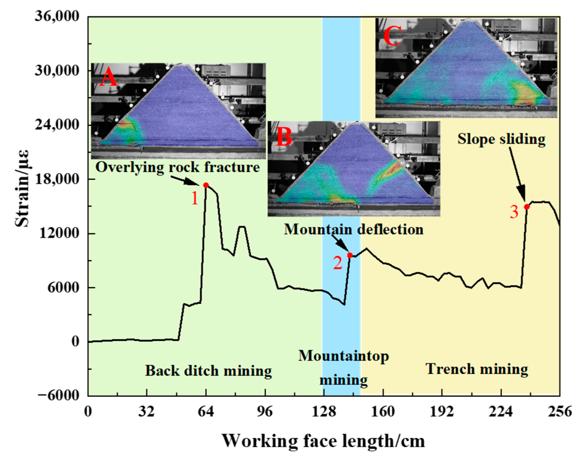
Figure 14 and draw the change curve of the peak point of the horizontal optical fiber H1 during the mining process of the working face, combined with the DIC strain nephogram for joint analysis. As shown in
Figure 17, panel A shows the overburden fracture in the back ditch mining stage. Panel B shows the deflection of the mountain during the mountaintop mining stage. Panel C shows the slope sliding during the trench mining stage.
During the back ditch mining stage, the stability of the mountain structure is good at the initial stage of the working face excavation, and the peak point of strain hardly changes. When the overburden is obviously broken, the peak point of strain of the optical fiber suddenly increases to peak point 1. The strain at the peak point increases from 4304 µε to 17,336 µε, and the growth rate of strain at the peak point is 302.7%. With the advancement of the working face, the strain at the peak point gradually decreases. This process occurs with the periodic fracture of the overlying rock. When the mountain deflects, the peak point of strain of the optical fiber suddenly increases again to peak point 2. The strain at the peak point increases from 4084 µε to 9584 µε, and the growth rate of the strain at the peak point is 134.7%. Then, it enters the trench mining stage, and the strain at the peak point continues to decrease. When the slope slip occurs, the peak point of strain suddenly increases to peak point 3. The strain at the peak point increases from 5980 µε to 14,944 µε, and the growth rate of strain at the peak point is 149.9%. It can be seen that the strain at the peak point of the horizontal optical fiber H1 will increase significantly when the mountain is broken, the mountain deflects, and the slope slides.
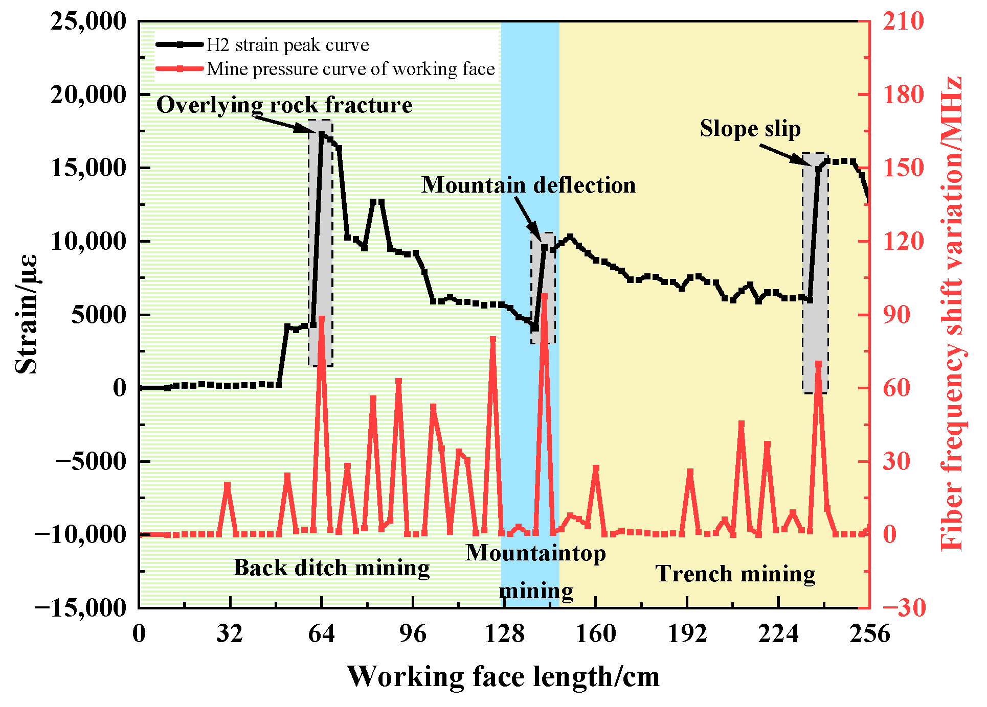
In combination with the above peak point changes, the changes in the peak point of the horizontal optical fiber H1 are compared to the pressure on the working face, as shown in
Figure 18. The peak point of the horizontal optical fiber H1 increases significantly when the overlying rock breaks, the mountain deflects, and the slope slides. The corresponding working face has strong ground pressure behavior. The ground pressure intensities of overburden failure, mountain deflection, and slope sliding are 88.4 MHz, 97.6 MHz, and 69.9 MHz, respectively, and the average periodic weighting intensity is 85.3 MHz. Compared to the average periodic weighting strength during other weighting periods, the average increase rate is 99.9%. The peak point of the sudden increase corresponds to the strong ground pressure behavior position of the working face (as shown in the gray dotted box in the figure).
The comparative analysis results show that the strong ground pressure behavior of the working face can be characterized by the horizontal optical fiber. When the peak point of the horizontal optical fiber has an obvious sudden increase in strain and the growth rate of strain is greater than 100%, the working face will exhibit strong ground pressure behavior.
5.4. Field Measurement of Mine Pressure in the Working Face
The 010204 working face started mining on 3 November 2022. The pressure data of 14 hydraulic supports with support numbers of 2, 10, 20, …, 110, 120, and 129 are selected to analyze the movement and failure of the roof and the stress of the supports. The rated resistance and initial support force of the supports at the working face are 36.5 MPa and 26.5 MPa, respectively. When the resistance of the supports reaches 90% (33.0 MPa) of the rated working resistance, that is, the average coefficient of load increase exceeds 1.25, the supports will give an alarm (see
Table 3 for the average coefficient of load increase and alarm rate at different mining stages).
The average coefficient of load increase in the support in the back ditch mining stage is 1.37, and the alarm rate is 49.0%. The support resistance is significantly higher than that in other mining stages, and the support alarm is frequent. It shows that the periodic weighting in the back ditch mining stage is more severe than that in other mining stages. The average coefficient of load increase in the supports in the mountaintop mining stage and the trench mining stage are both 1.22, making them less than the alarm value of 1.25. The alarm rate is also low, and the mine pressure behavior is relatively mild.
The measured pressure characteristics of the field are basically consistent with the model experiment pressure characteristics, which shows that the distributed optical fiber is correct and feasible to characterize the pressure. It provides a new method for mine pressure monitoring.


