Artificial Neural Network Modeling of a CMOS Differential Low-Noise Amplifier Using the Bayesian Regularization Algorithm
Abstract
1. Introduction
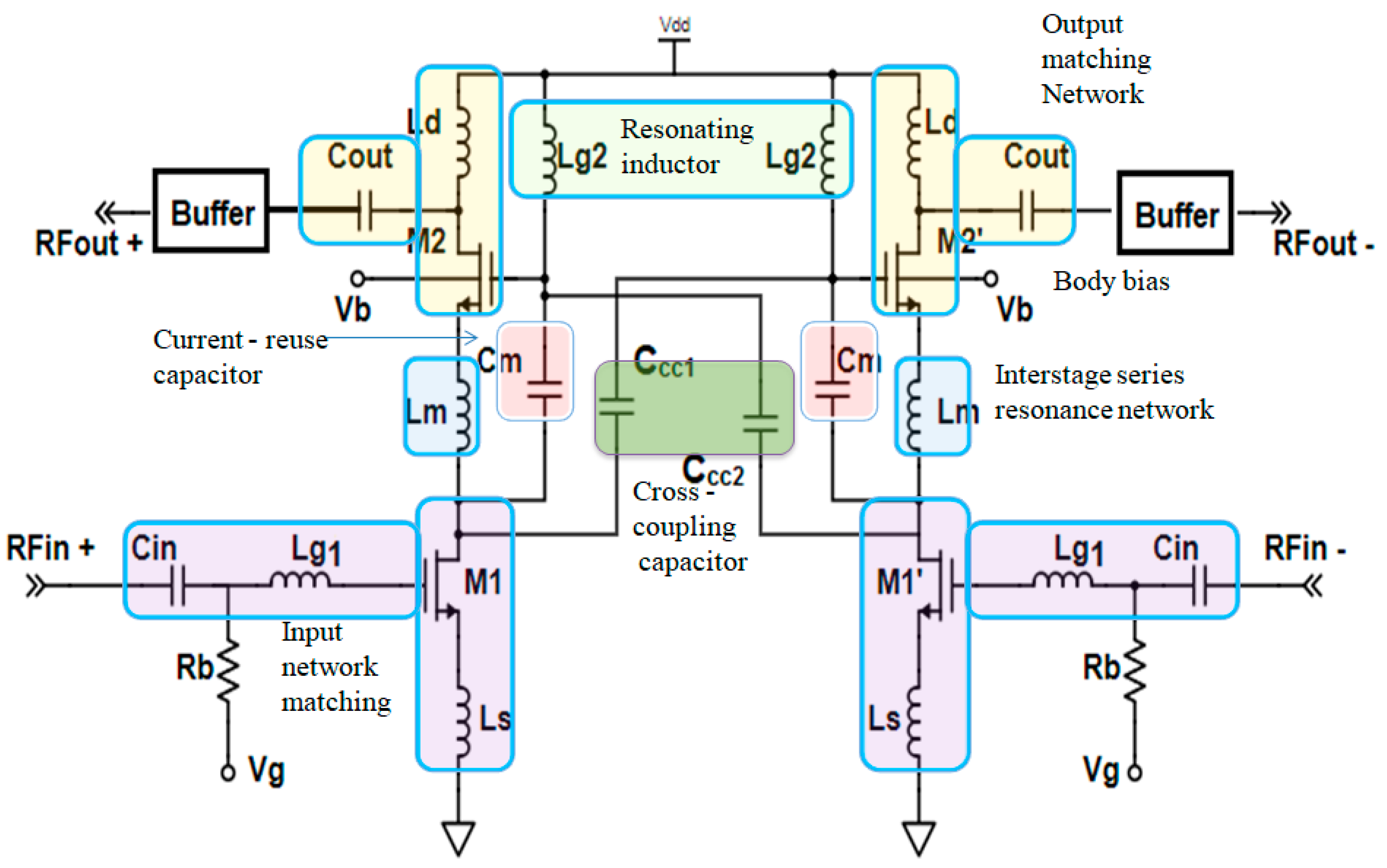
2. CMOS Differential LNA
2.1. Small-Signal Equivalent of the Proposed Differential LNA
2.1.1. Gain Improvement Using Current-Reuse Technique
2.1.2. LNA Linearity Improvement Using Capacitor Cross-Coupling Technique
2.1.3. Transconductance Improvement with Low-Power Body Biasing Technique
2.2. Impedance Calculation at Input and Output
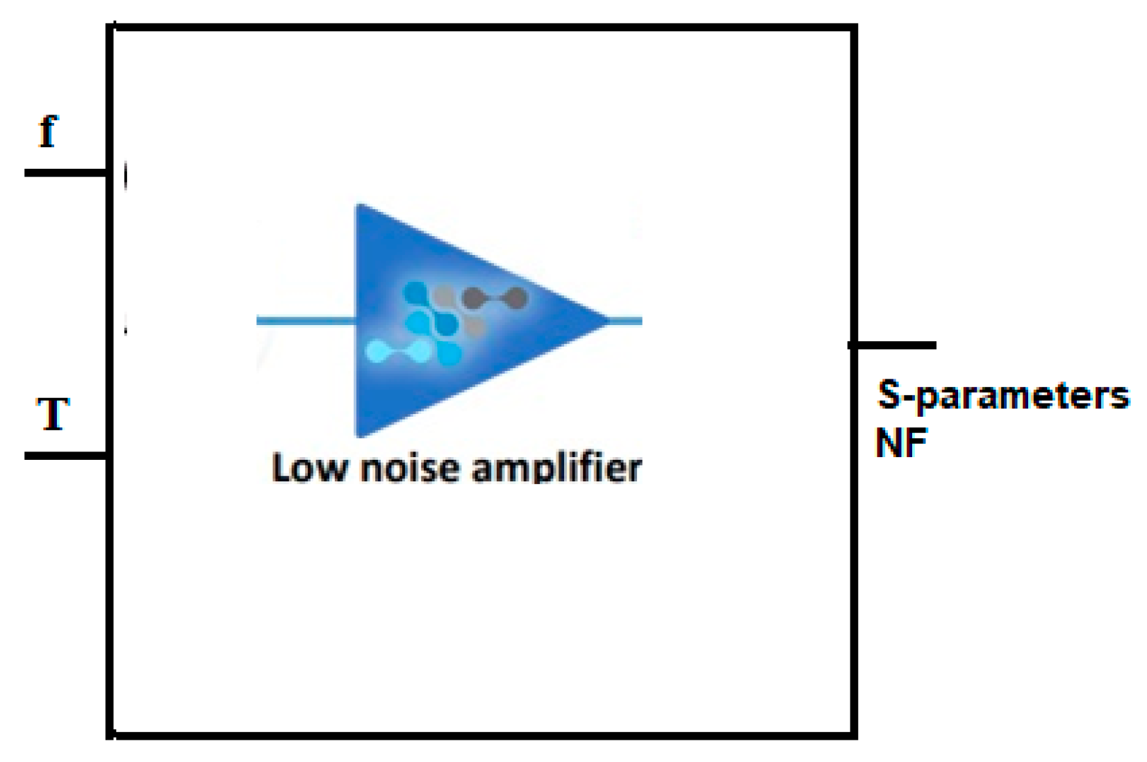
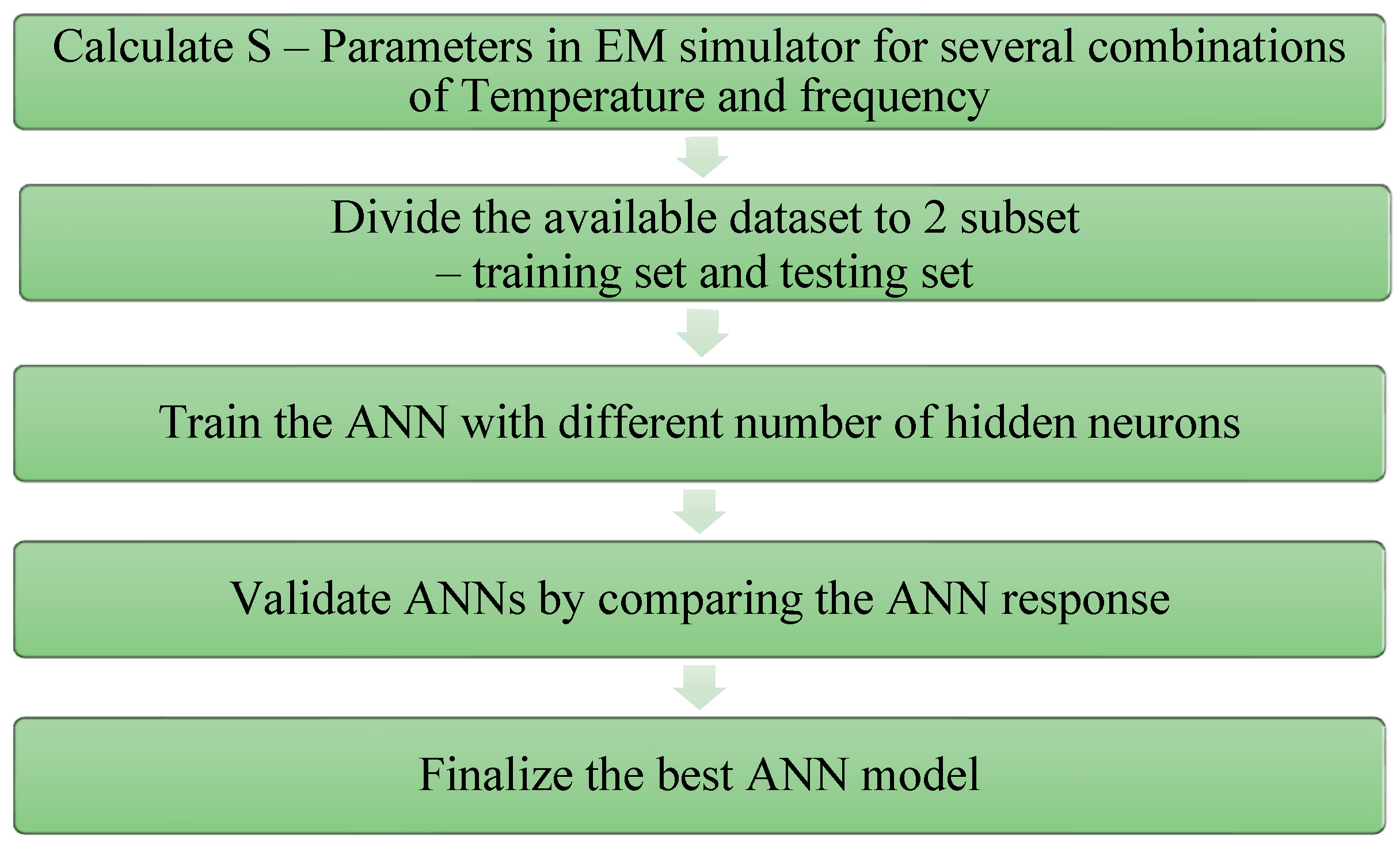
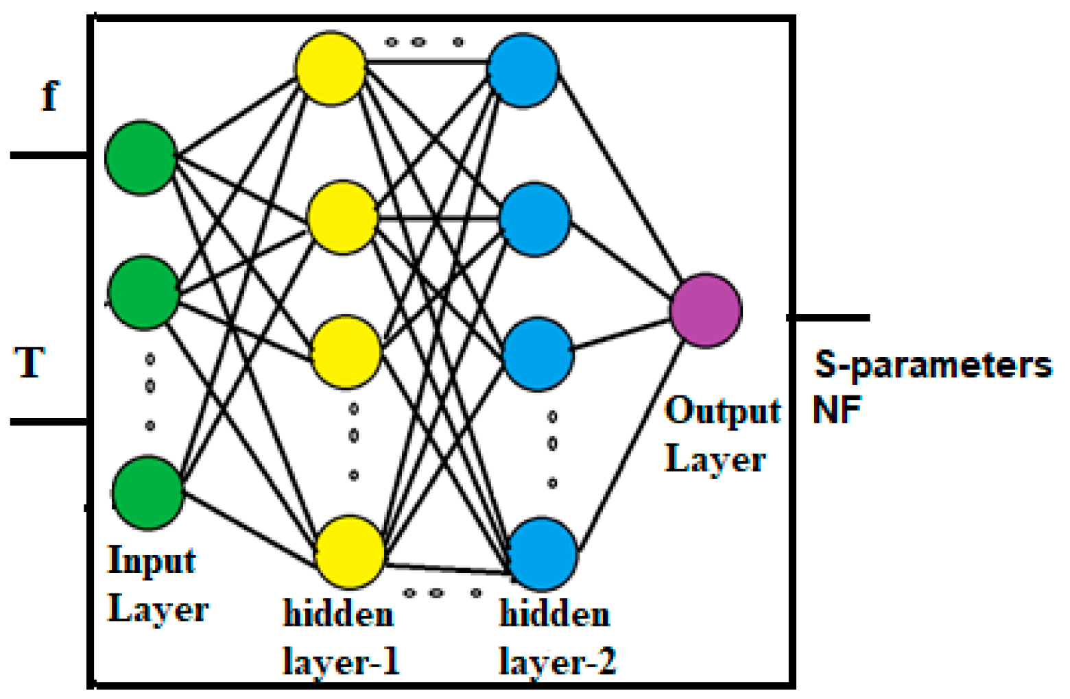
3. Development of ANN Model
Neural Network Model for the Proposed CMOS Differential LNA
4. Results and Discussion
4.1. Effect of Body Biasing and Current-Reuse Technique on LNA Gain
4.2. Effect of Capacitor Cross-Coupling on LNA Linearity
4.3. Simulation Results at Different Process Corners
4.4. Performance Comparison of Proposed LNA with Existing State of Art
4.5. Performance Comparison with Different NN Models
4.6. Performance Comparison between Cadence Simulation and Developed ANN Results
5. Performance Comparison with the Existing State of Art
6. Conclusions
Author Contributions
Funding
Data Availability Statement
Acknowledgments
Conflicts of Interest
References
- Kim, T.-S.; Kim, B.-S. Post-Linearization of Cascode CMOS Low Noise Amplifier Using Folded PMOS IMD Sinker. IEEE Microw. Wirel. Compon. Lett. 2006, 16, 182–184. [Google Scholar]
- Lee, T.H. The Design of CMOS Radio Frequency Integrated Circuits; Cambridge University Press: Cambridge, UK, 2000. [Google Scholar]
- Woo, S.; Kim, W.; Lee, C.H.; Kim, H.; Laskar, J. A Wideband Low-Power CMOS LNA With Positive–Negative Feedback forNoise, Gain, and Linearity Optimization. IEEE Trans. Microw. Theory Tech. 2012, 60, 3169–3178. [Google Scholar] [CrossRef]
- Alam, S.K.; DeGroat, J. A 2 GHz variable gain low noise amplifier in 0.18-μm CMOS. Analog Integr. Circ. Sig. Process. 2008, 56, 37–42. [Google Scholar] [CrossRef]
- Fan, X.; Zhang, H.; Sánchez-Sinencio, E. A Noise Reduction and Linearity Improvement Technique for a Differential Cascode LNA. IEEE J. Solid-State Circuits 2008, 43, 588–599. [Google Scholar] [CrossRef]
- Cen, M.; Song, S. A Differential Cascode Low Noise Amplifier Based on a Positive Feedback Gain Enhancement Technique. J. Mach. Mach. Commun. 2015, 1, 229–244. [Google Scholar] [CrossRef]
- Kalamani, C. Design of Differential LNA and Double Balanced Mixer using 180nm CMOS Technology. Microprocess. Microsyst. 2019, 71, 102850. [Google Scholar] [CrossRef]
- Wang, W.; Wang, C. Capacitor Cross-Coupled Fully differential CMOS Folded Cascode LNAs with Ultra Low Power Consumption. Wirel. Pers. Commun. 2014, 78, 45–55. [Google Scholar] [CrossRef]
- Muhamad, M.; Soin, N.; Ramiah, H.; Noh, N.M.; Chong, W.K. Design of CMOS differential LNA at 2.4 GHz. In Proceedings of the 2013 IEEE International Conference of Electron Devices and Solid-State Circuits, Hong Kong, China, 3–5 June 2013. [Google Scholar]
- Kumar, M.G.L.; Regulagadda, S.S.; Das, J.K.; Dutta, A. Design of Current Reuse based Differential Merged LNA-Mixer (DMLNAM) and Two-stage Dual Band LNA with two Gain modes in 65 nm technology. In Proceedings of the 2015 IEEE Asia Pacific Conference on Postgraduate Research in Microelectronics and Electronics, Hyderabad, India, 27–29 November 2015; pp. 98–103. [Google Scholar]
- Kargaran, E.; Mafinejad, Y.; Mafinezhad, K.; Nabovati, H. A new gm boosting current reuse folded cascode LNA. IEICE Electron. Express 2013, 10, 20130264. [Google Scholar] [CrossRef]
- Shankar, S.U.; Dhas, M.D.K. Design and Performance Measure of 5.4 GHZ CMOS Low Noise Amplifier using Current ReuseTechnique in 0.18μmTechnology. Procedia Comput. Sci. 2015, 47, 135–143. [Google Scholar] [CrossRef][Green Version]
- Dai, R.; Zheng, Y.; He, J.; Liu, G.; Kong, W.; Zou, S. A 0.5-V novel complementary current-reused CMOSLNAfor 2.4 GHz medical application. J. Microelectron. 2016, 55, 64–69. [Google Scholar] [CrossRef]
- Chang, C.-H.; Onabajo, M. Analysis and Demonstration of an IIP3 Improvement Technique for Low-Power RF Low-Noise Amplifiers. IEEE Trans. Circuits Syst. I Regul. Pap. 2018, 65, 859–869. [Google Scholar] [CrossRef]
- Liu, H.J.; Zhang, Z.F. An Ultra-Low Power CMOS LNA for WPAN Applications. IEEE Microw. Wirel. Compon. Lett. 2017, 27, 174–176. [Google Scholar] [CrossRef]
- Fiorelli, R.; Silveira, F.; Peralias, E. MOST moderate weak inversion region as the optimum design zone for CMOS 2.4-GHz CS-LNAs. IEEE Trans. Microw. Theory Tech. 2014, 62, 556–566. [Google Scholar] [CrossRef]
- Li, C.-H.; Liu, Y.-L.; Kuo, C.-N. A 0.6-V 0.33-mW 5.5-GHz receiver front-end using resonator coupling technique. IEEE Trans. Microw. Theory Tech. 2011, 59, 1629–1638. [Google Scholar] [CrossRef]
- Lai, M.-T.; Tsao, H.-W. Ultra-Low Power Cascaded CMOS LNA With Positive Feedback and Bias Optimization. IEEE Trans. Microw. Theory Tech. 2013, 61, 1934–1945. [Google Scholar] [CrossRef]
- Singh, V.; Arya, S.K.; Kumar, M. A 0.7V, Ultra-Wideband Common Gate LNA with Feedback BodyBias Topology for Wireless Applications. J. Low Power Electron. Appl. 2018, 8, 42. [Google Scholar] [CrossRef]
- Wang, T.-P. Minimized Device Junction Leakage Current at Forward-Bias Body and Applications for Low-Voltage Quadruple-Stacked Common-Gate Amplifier. IEEE Trans. Electron Devices 2014, 61, 1231–1236. [Google Scholar] [CrossRef]
- Zhang, H.; Sánchez-Sinencio, E. Linearization Techniques for CMOS Low Noise Amplifiers: A Tutorial. IEEE Trans. Circuits Syst. I Regul. Pap. 2011, 58, 22–36. [Google Scholar] [CrossRef]
- Kargaran, E.; Mafinejad, Y.; Mafinezhad, K.; Nabovati, H. Highly Linear Folded Cascode LNA. IEICE Electron. Express 2013, 10, 20130557. [Google Scholar] [CrossRef]
- Aparin, V.; Larson, L.E. Linearization of monolithic LNAs using low-frequency low-impedance input termination. In Proceedings of the 29th European Solid-State Circuits Conference, Estoril, Portugal, 16–18 September 2003; pp. 137–140. [Google Scholar]
- Aparin, V.; Brown, G.; Larson, L.E. Linearization of CMOS LNAs via optimum gate biasing. In Proceedings of the 2004 IEEE International Symposium on Circuits and Systems, Vancouver, BC, Canada, 23–26 May 2004; pp. 748–751. [Google Scholar]
- Lou, S.; Luong, H.C. AlinearizationtechniqueforRFreceiverfront-endusingsecond-orderintermodulationinjection. IEEE J. Solid-State Circuits 2008, 43, 2404–2412. [Google Scholar] [CrossRef]
- Jin, T.H.; Kim, T.W. A 5.5-mW +9.4-dBm IIP3 1.8dB NF CMOS LNA Employing Multiple Gated Transistors with Capacitance Desensitization. IEEE Trans. Microw. Theory Tech. 2010, 58, 2529–2537. [Google Scholar] [CrossRef]
- Kim, Y.M.; Han, H.; Kim, T.W. A 0.6-V +4dBm IIP3 LC folded cascode CMOS LNA with gm linearization. IEEE Trans. Circuits Syst. II Express Briefs 2013, 60, 122–126. [Google Scholar]
- Salim, Z.Z.M.; Muhamad, M.; Hussin, H.; Ahmad, N. CMOS LNA Linearization Employing Multiple Gated Transistors. In Proceedings of the 2019 IEEE International Conference on Telecommunication Systems, Services, and Applications (TSSA), Bali, Indonesia, 3–4 October 2019. [Google Scholar]
- Ma, L.; Wang, Z.-G.; Xu, J.; Amin, N.M. A High Linearity Wideband Common-Gate LNA with Differential Active Inductor. IEEE Trans. Circuits Syst. II Express Briefs 2017, 64, 402–406. [Google Scholar] [CrossRef]
- Kumaravel, S.; Kukde, A.; Venkataramani, B.; Raja, R. A high linearity and high gain Folded Cascode LNA for narrow band receiver applications. Microelectron. J. 2016, 54, 101–108. [Google Scholar] [CrossRef]
- Tarighat, A.P.; Yargholi, M. A CMOS low noise amplifier with employing noise cancellation and modified derivative superposition technique. Microelectron. J. 2016, 54, 116–125. [Google Scholar] [CrossRef]
- Raja, R.; Venkataramani, B.; Kishore, K.H. A 1-V 2.4 GHz Low-Power CMOS LNA Using Gain-Boosting and Derivative Superposition Techniques for WSN. Wirel. Pers. Commun. 2017, 96, 383–402. [Google Scholar] [CrossRef]
- Rafati, M.; Qasemi, S.R.; Amiri, P. A 0.65V, linearized cascade UWB LNA by application of modified derivative superpositiontechnique in 130nm CMOS technology. Analog Integr. Circuits Signal Process. 2019, 99, 693–706. [Google Scholar] [CrossRef]
- Chang, C.-P.; Chien, W.-C.; Su, C.-C.; Wang, Y.-H.; Chen, J.-H. Linearity improvement of cascode CMOS LNA using a diode connected NMOS transistor with a parallel RC circuit. Prog. Electromagn. Res. C 2010, 17, 29–38. [Google Scholar] [CrossRef]
- Guo, B.; Chen, J.; Jin, H. A linearized common-gate low-noise amplifier using active cross-coupled feedback technique. Analog Integr. Circuits Signal Process. 2016, 89, 239–248. [Google Scholar] [CrossRef]
- Wu, Y.; Kim, H.; Jonsson, F.; Ismail, M.; Olsson, H. Nonlinearity Analysis of a Short Channel CMOS Circuit for RFIC Applications. In VLSI: Systems on a Chip; IFIP International Federation for Information Processing; Silveira, L.M., Devadas, S., Reis, R., Eds.; Springer: Boston, MA, USA, 1999; Volume 34, pp. 61–68. [Google Scholar]
- Sorkhabi, S.E.; Mosavi, M.R.; Rafei, M. Low Noise amplifier synthesis using multidimensional MLP neural network. IETE J. Res. 2018, 64, 374–386. [Google Scholar] [CrossRef]
- Kumar, S.; Kumari, S. Design of low power, high gain LNA for WCDMA range and parameters extraction using Artificial Neural Network (ANN). In Proceedings of the 2015 IEEE Power, Communication and Information Technology Conference (PCITC), Bhubaneswar, India, 15–17 October 2015. [Google Scholar] [CrossRef]
- Güneş, F.; Çağlar, M.F. A Novel Neural Smith Chart for use in Microwave circuitry. Int. J. RF Microw. Comput. Eng. 2008, 19, 218–229. [Google Scholar] [CrossRef]
- Gorissen, D.; De Tommasi, L.; Crombecq, K.; Dhaene, T. Sequential modeling of a low noise amplifier with neural networks and active learning. Neural Comput. Appl. 2009, 18, 485–494. [Google Scholar] [CrossRef]
- Karimi, G.; Sedaghat, S.B.; Banitalebi, R. Designing and modeling of ultra-low voltage and ultra-low power LNA using ANN and ANFIS for Bluetooth applications. Neurocomputing 2013, 120, 504–508. [Google Scholar] [CrossRef]
- Dumesnil, E.; Nabki, F.; Boukadoum, M. RF-LNA circuit synthesis using an array of artificial neural networks with Constrained Inputs. In Proceedings of the 2015 IEEE International Symposiumon Circuits and Systems (ISCAS), Lisbon, Portugal, 24–27 May 2015; pp. 573–576. [Google Scholar] [CrossRef]
- Singh, S.; Chopra, P.K. Artificial Neural Network approach for LNA design of GPS receiver. Opt. Mem. Neural Netw. 2016, 25, 236–242. [Google Scholar] [CrossRef]
- Güneş, F.; Demirel, S.; Nesil, S. Design optimization of LNAs and reflect array antennas using the full-wave simulation-based artificial intelligence models with the novel metaheuristic algorithms. In Simulation-Driven Modeling and Optimization; Springer Proceedings in Mathematics & Statistics; Koziel, S., Leifsson, L., Yang, X.S., Eds.; Springer: Cham, Switzerland, 2016; Volume 153. [Google Scholar] [CrossRef]
- Payala, A.; Anand, R. Modelling of navigation based LNA parameters using neural network technique. Opt. Mem. Neural Netw. 2017, 26, 192–198. [Google Scholar] [CrossRef]
- Xhafa, X.; Yelten, M.B. Design of a tunable LNA and its variability analysis through surrogate modeling. Int. J. Numer. Model. Electron. Netw. Devices Fields 2020, 33, e2724. [Google Scholar] [CrossRef]


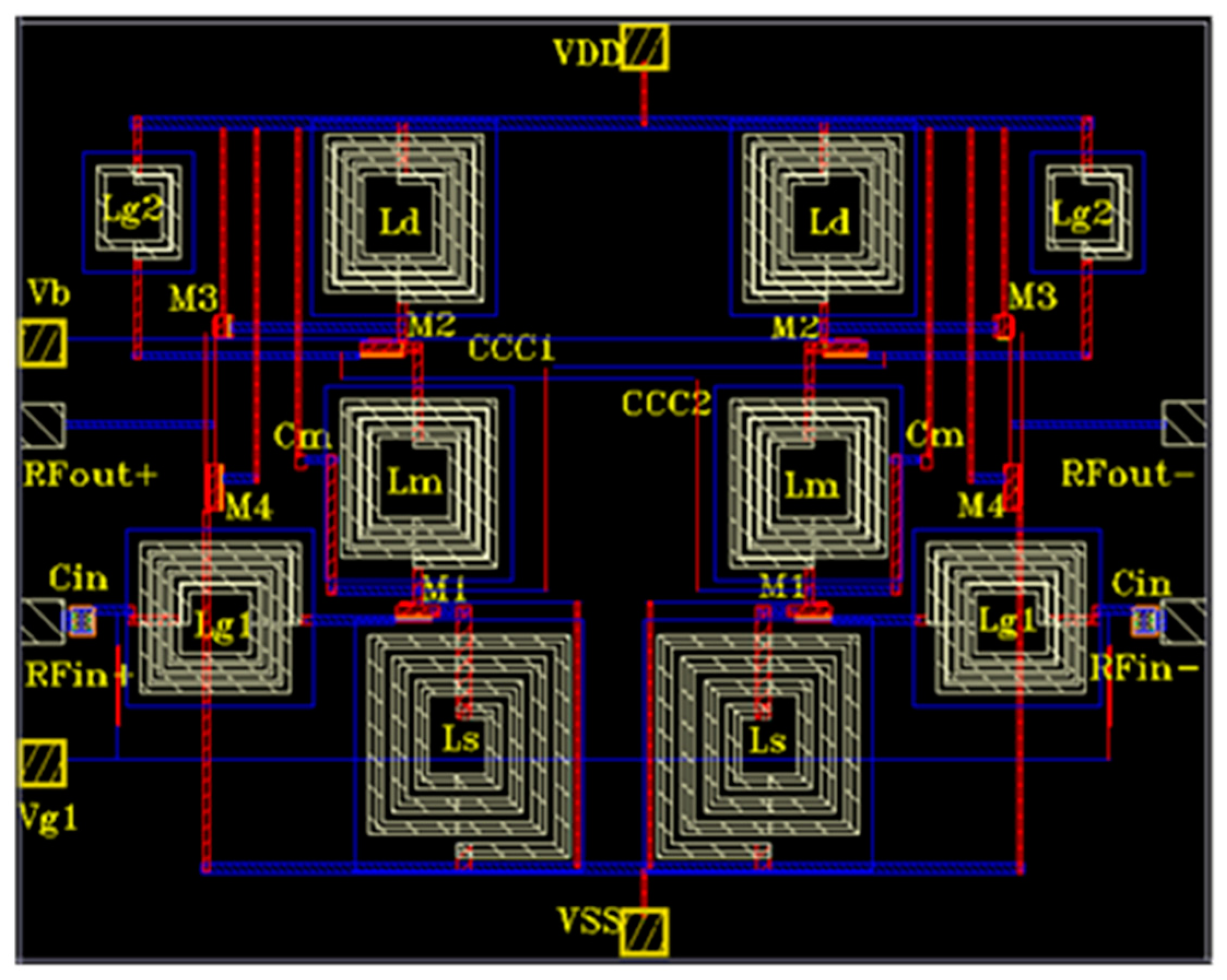

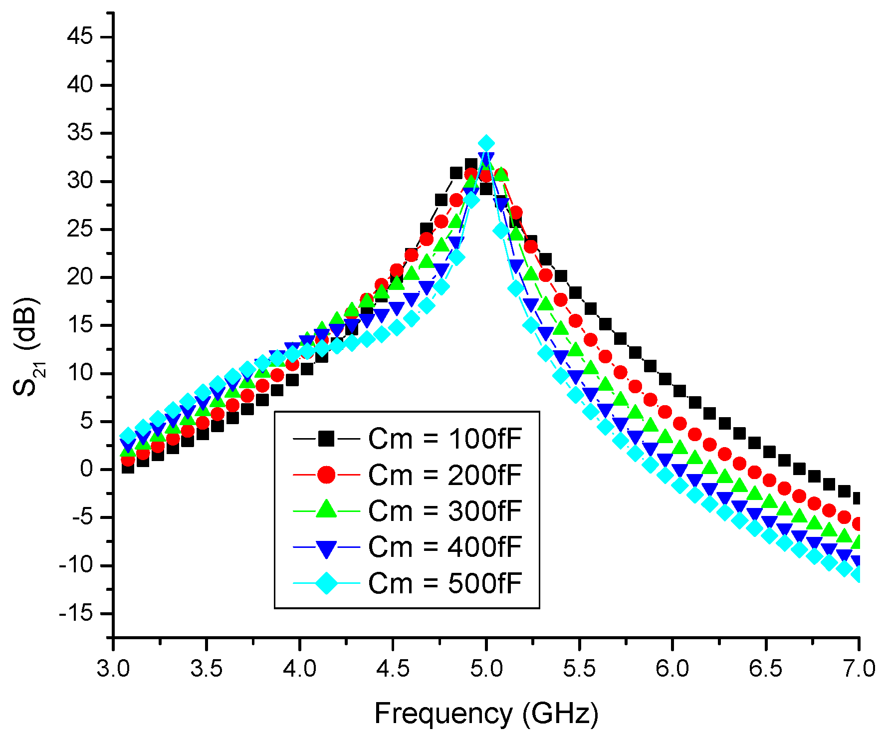

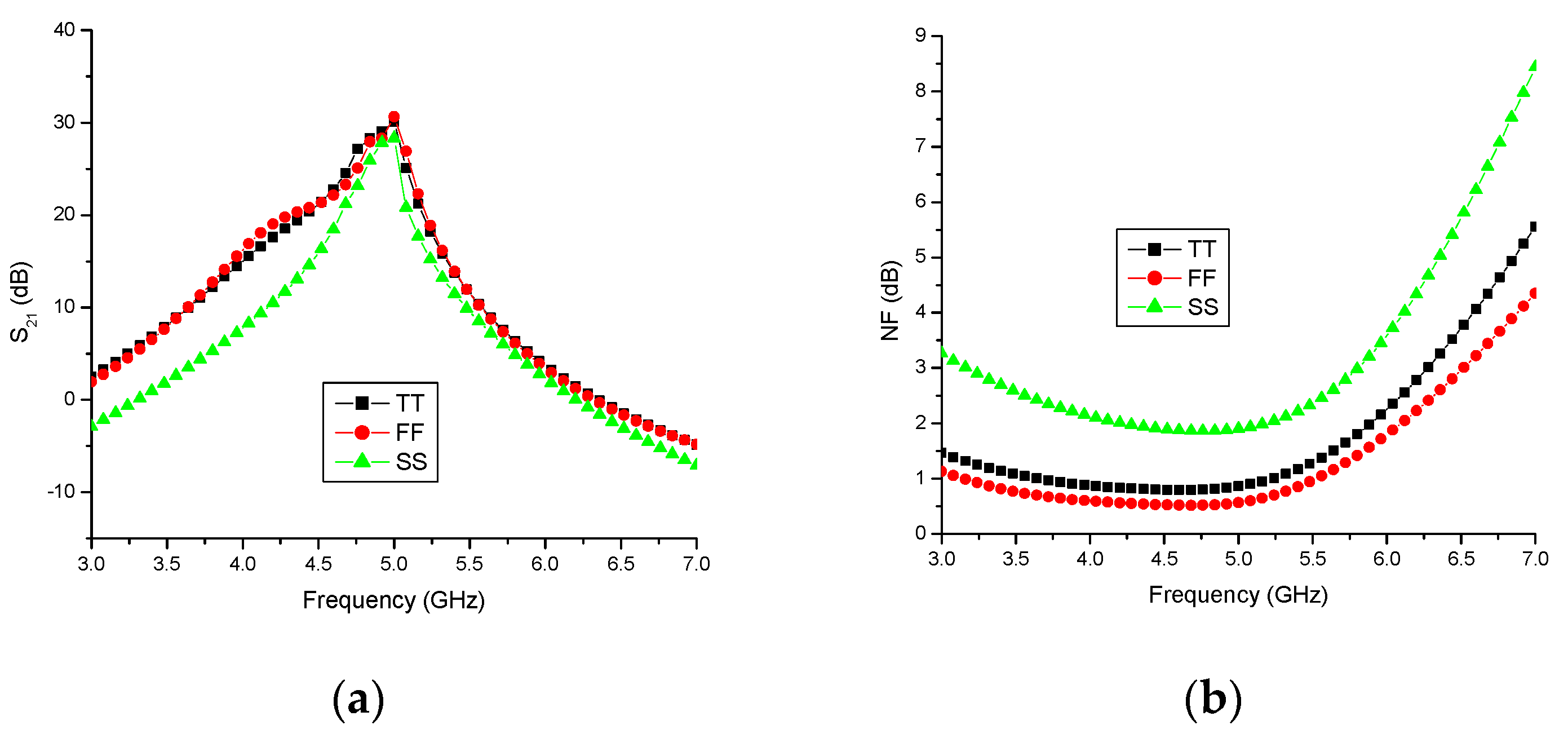

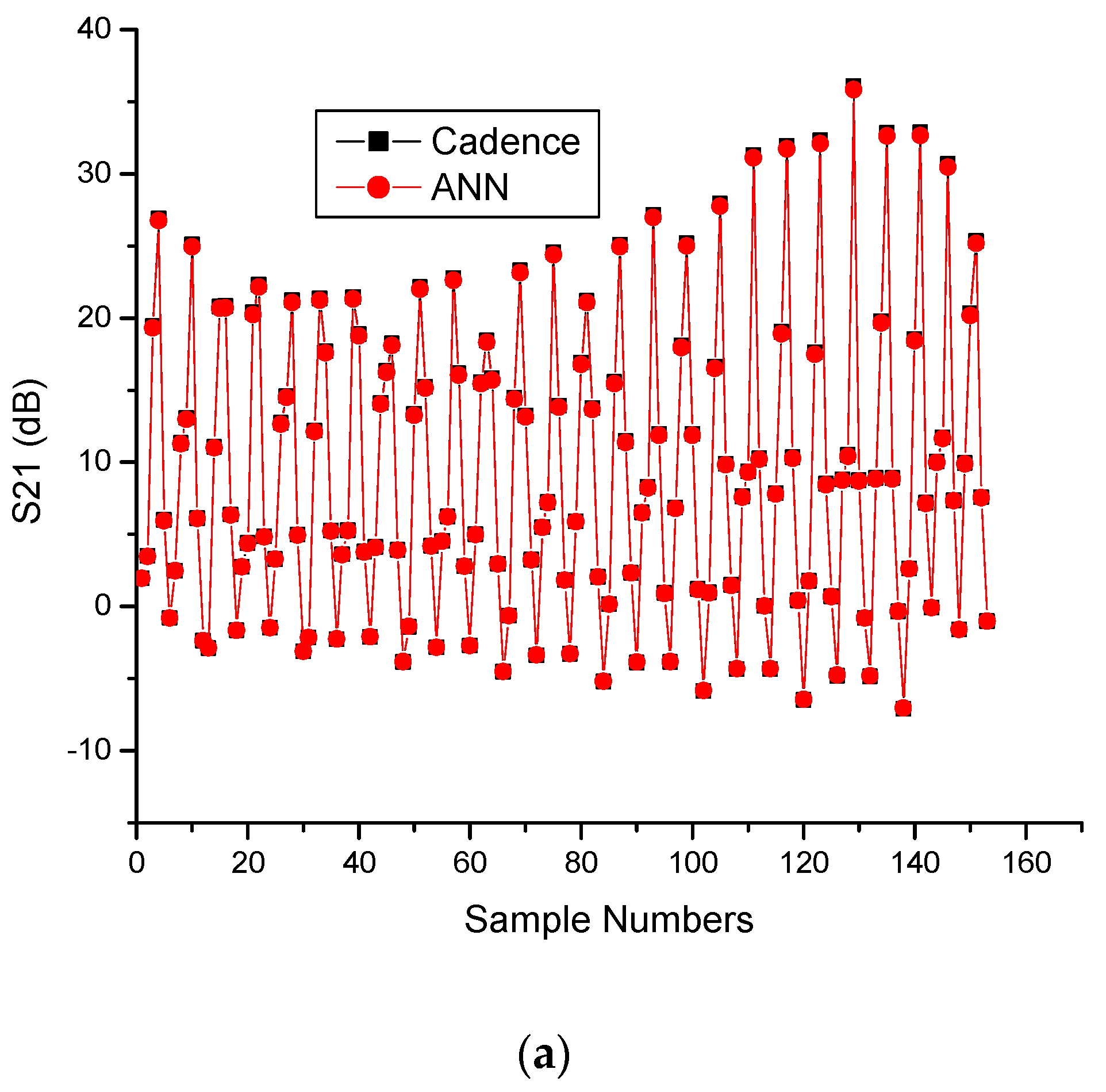

| S. No | Algorithm | Abbreviation |
|---|---|---|
| 1 | scg | Scaled conjugate gradient back propagation |
| 2 | cgb | Conjugate gradient back propagation with Powell/Beale restarts |
| 3 | bfg | BFGS quasi-Newton back propagation |
| 4 | cgp | Conjugate gradient back propagation with Polak–Ribiére updates |
| 5 | gda | Gradient descent with adaptive learning rate back propagation |
| 6 | gd | Gradient descent back propagation |
| 7 | gdm | Gradient descent with momentum back propagation |
| 8 | gdx | Gradient descent with momentum and adaptive learning rate back propagation |
| 9 | lm | Levenberg–Marquardt back propagation |
| 10 | cgf | Conjugate gradient back propagation with Fletcher–Reeves updates |
| 11 | oss | One-step secant back propagation |
| 12 | rp | Resilient back propagation |
| 13 | Br | Bayesian regularization |
| Component | M1 | M2 | Ls | Lg1 | Lg2 | Lm | Cin | Cm | Ccc1 | Ccc2 |
|---|---|---|---|---|---|---|---|---|---|---|
| Values | 138 µm | 216 µm | 1.15 nH | 2 nH | 0.05 nH | 2.29 nH | 1.63 pF | 0.2 pF | 0.1 pF | 0.1 pF |
| Parameter | TT 27 °C | FF 0 °C | SS 80 °C |
|---|---|---|---|
| S11 (dB) | −13.3 | −14.5 | −12.1 |
| S22 (dB) | −13.1 | −14.8 | −11.3 |
| S21 (dB) | 29.5 | 30.6 | 28.4 |
| NF (dB) | 1.2 | 0.7 | 1.9 |
| Pdc (mW) | 19.3 | 17.2 | 21.3 |
| State of the Art | Freq (GHz) | Tech (µm) | S21 (dB) | NF (dB) | Vdd (V) | Pdc (mW) | IIP3 (dBm) | FoM | Remarks |
|---|---|---|---|---|---|---|---|---|---|
| [6] | 5.8 | 0.18 | 18.66 | 2.03 | 1.8 | 7.58 | - | 6.07 | Low gain, high NF |
| [7] | 2.4 | 0.18 | 20.285 | 1 | 1.8 | 167.1 | - | 0.51 | High power consumption |
| [8] | 5.5 | 0.18 | 16.5 | 1.53 | 0.5 | 0.89 | −17.2 | 0.67 | Low gain, low IIP3 |
| This work | 5 | 0.18 | 29.5 * | 1.2 | 0.9 | 19.3 | 0.2 | 24.26 | High gain, low NF, and better linearity |
| Algorithm | PatternNet | FitNet | Cascade ForwardNet |
|---|---|---|---|
| SCG | 97.33 | 98 | 97.33 |
| CGB | 76 | 97 | 98 |
| BFG | 27 | 35 | 40 |
| CGP | 99.1 | 96 | 92.6 |
| GDA | 26.67 | 8.6 | 2 |
| GDA | 2 | 4 | 4 |
| GDM | 5.3 | 4 | 1.3 |
| GDX | 58.6 | 34 | 25.3 |
| LM | 3.3 | 4 | 5 |
| CGF | 82.6 | 86.67 | 93.33 |
| OSS | 29 | 77.3 | 86.67 |
| RP | 66.7 | 69.3 | 77.33 |
| BR | 99.34 | 98 | 99 |
| Algorithm | Accuracy(%) | MRE | RMSE |
|---|---|---|---|
| SCG | 97.33 | 2.67 | 1.63 |
| CGB | 76 | 24 | 4.90 |
| BFG | 27 | 73 | 8.54 |
| CGP | 99.1 | 0.9 | 0.95 |
| GDA | 26.67 | 73.33 | 8.56 |
| GDA | 2 | 98 | 9.90 |
| GDM | 5.3 | 94.7 | 9.73 |
| GDX | 58.6 | 41.4 | 6.43 |
| LM | 3.3 | 96.7 | 9.83 |
| CGF | 82.6 | 17.4 | 4.17 |
| OSS | 29 | 71 | 8.43 |
| RP | 66.7 | 33.3 | 5.77 |
| BR | 99.34 | 0.66 | 0.81 |
| Hidden Neurons | S21 | NF |
|---|---|---|
| 5 | 83.57 | 86.30 |
| 10 | 90.23 | 92.71 |
| 20 | 97.14 | 96.42 |
| 25–30 | 99.97 | 99.79 |
| Sample No. | Cadence—S21 (Real Values) | ANN—S21 (Predicted Values) | MRE | RMSE | Cadence—NF (Real Values) | ANN—NF (Predicted Values) | MRE | RMSE |
|---|---|---|---|---|---|---|---|---|
| 1 | −18.1001 | −17.9806 | −0.1195 | 0.345688 | 3.71105 | 3.68656 | 0.02449 | 0.156493 |
| 2 | −7.32325 | −7.27491 | −0.04834 | 0.219864 | 4.72765 | 4.69645 | 0.0312 | 0.176635 |
| 3 | 13.907 | 13.81521 | 0.09179 | 0.302969 | 0.85553 | 0.84988 | 0.00565 | 0.075166 |
| 4 | 31.16381 | 30.95813 | 0.20568 | 0.45352 | 0.92032 | 0.91425 | 0.00607 | 0.07791 |
| 5 | 10.4285 | 10.35967 | 0.06883 | 0.262355 | 2.97907 | 2.95941 | 0.01966 | 0.140214 |
| 6 | 8.28715 | 8.23246 | 0.05469 | 0.233859 | 4.23488 | 4.20693 | 0.02795 | 0.167183 |
| 7 | −6.22354 | −6.18246 | −0.04108 | 0.202682 | 2.9065 | 2.88731 | 0.01919 | 0.138528 |
| 8 | −7.25494 | −7.20706 | −0.04788 | 0.218815 | 2.0291 | 2.01571 | 0.01339 | 0.115715 |
| 9 | 4.95072 | 4.91804 | 0.03268 | 0.180776 | 2.96014 | 2.94061 | 0.01953 | 0.13975 |
| 10 | 34.69036 | 34.46141 | 0.22895 | 0.478487 | 0.63707 | 0.63287 | 0.0042 | 0.064807 |
| 11 | 8.71366 | 8.65615 | 0.05751 | 0.239812 | 2.17553 | 2.16117 | 0.01436 | 0.119833 |
| 12 | 0.79462 | 0.78938 | 0.00524 | 0.072388 | 6.59107 | 6.54757 | 0.0435 | 0.208567 |
| 13 | −16.9761 | −16.864 | −0.1121 | 0.334813 | 7.08496 | 7.0382 | 0.04676 | 0.216241 |
| 14 | 2.83459 | 2.81588 | 0.01871 | 0.136785 | 1.40329 | 1.39403 | 0.00926 | 0.096229 |
| 15 | 5.60129 | 5.56432 | 0.03697 | 0.192276 | 1.1591 | 1.15145 | 0.00765 | 0.087464 |
| 16 | 31.96165 | 31.7507 | 0.21095 | 0.459293 | 2.06107 | 2.04747 | 0.0136 | 0.116619 |
| 17 | 16.14315 | 16.03661 | 0.10654 | 0.326405 | 1.73748 | 1.72601 | 0.01147 | 0.107098 |
| 18 | −0.88958 | −0.88371 | −0.00587 | 0.076616 | 5.23356 | 5.19902 | 0.03454 | 0.185849 |
| 19 | −16.8985 | −16.787 | −0.1115 | 0.333916 | 3.47562 | 3.45268 | 0.02294 | 0.15146 |
| 20 | −6.08266 | −6.04252 | −0.04014 | 0.20035 | 4.49132 | 4.46167 | 0.02965 | 0.172192 |
| 21 | 15.62884 | 15.52568 | 0.10316 | 0.321185 | 0.81078 | 0.80543 | 0.00535 | 0.073144 |
| 22 | 33.539 | 33.31764 | 0.22136 | 0.470489 | 0.95501 | 0.9487 | 0.00631 | 0.079436 |
| 23 | 9.0474 | 8.98769 | 0.05971 | 0.244356 | 3.26576 | 3.24421 | 0.02155 | 0.146799 |
| 24 | 7.52286 | 7.47321 | 0.04965 | 0.222823 | 4.57863 | 4.54841 | 0.03022 | 0.173839 |
| 25 | −5.25111 | −5.21646 | −0.03465 | 0.186145 | 2.68156 | 2.66386 | 0.0177 | 0.133041 |
| Sample No. | Cadence—S21 (Real Values) | ANN—S21 (Predicted Values) | MRE | RMSE | Cadence—NF (Real Values) | ANN—NF (Predicted Values) | MRE | RMSE |
|---|---|---|---|---|---|---|---|---|
| 1 | −5.99297 | −5.95342 | −0.03955 | 0.198872 | 1.89999 | 1.88745 | 0.01254 | 0.111982 |
| 2 | 6.57258 | 6.5292 | 0.04338 | 0.208279 | 2.80927 | 2.79073 | 0.01854 | 0.136162 |
| 3 | 32.24145 | 32.02865 | 0.2128 | 0.461303 | 0.663 | 0.65862 | 0.00438 | 0.066182 |
| 4 | 7.35635 | 7.30779 | 0.04856 | 0.220363 | 2.45318 | 2.43699 | 0.01619 | 0.12724 |
| 5 | −0.01017 | −0.0101 | 0.0001 | 0.008367 | 7.07881 | 7.03209 | 0.04672 | 0.216148 |
| 6 | −15.7674 | −15.6634 | −0.104 | 0.32249 | 6.74143 | 6.69693 | 0.0445 | 0.21095 |
| 7 | 4.01011 | 3.98364 | 0.02647 | 0.162696 | 1.306 | 1.29738 | 0.00862 | 0.092844 |
| 8 | 7.37583 | 7.32715 | 0.04868 | 0.220635 | 1.09624 | 1.089 | 0.00724 | 0.085088 |
| 9 | 32.12838 | 31.91633 | 0.21205 | 0.460489 | 2.05571 | 2.04214 | 0.01357 | 0.11649 |
| 10 | 14.9347 | 14.83613 | 0.09857 | 0.313959 | 1.99324 | 1.98008 | 0.01316 | 0.114717 |
| State of the Art | Algorithm Used | Frequency | Parameters Considered | Error | |
|---|---|---|---|---|---|
| Input | Output | ||||
| [37] | M-MLPNN | 4 GHz–6 GHz | 12 | 5 | -- |
| [38] | MLPNN | 1 GHz–4 GHz | - | 2 | 0.005 |
| [44] | MLPNN -LM | 100 MHz–8 GHz | 4 | 10 | -- |
| [45] | MLPNN-LM | 300 MHz–18 GHz | 4 | 10 | -- |
| [46] | Surrogate modeling | 2 GHz–3 GHz | 2 | 7 | 0.001 |
| Proposed work | MLPNN-BR | 5 GHz | 2 | 2 | 0.001 |
Disclaimer/Publisher’s Note: The statements, opinions and data contained in all publications are solely those of the individual author(s) and contributor(s) and not of MDPI and/or the editor(s). MDPI and/or the editor(s) disclaim responsibility for any injury to people or property resulting from any ideas, methods, instructions or products referred to in the content. |
© 2023 by the authors. Licensee MDPI, Basel, Switzerland. This article is an open access article distributed under the terms and conditions of the Creative Commons Attribution (CC BY) license (https://creativecommons.org/licenses/by/4.0/).
Share and Cite
Subburaman, B.; Thangaraj, V.; Balu, V.; Pandyan, U.M.; Kulkarni, J. Artificial Neural Network Modeling of a CMOS Differential Low-Noise Amplifier Using the Bayesian Regularization Algorithm. Sensors 2023, 23, 8790. https://doi.org/10.3390/s23218790
Subburaman B, Thangaraj V, Balu V, Pandyan UM, Kulkarni J. Artificial Neural Network Modeling of a CMOS Differential Low-Noise Amplifier Using the Bayesian Regularization Algorithm. Sensors. 2023; 23(21):8790. https://doi.org/10.3390/s23218790
Chicago/Turabian StyleSubburaman, Bhuvaneshwari, Vignesh Thangaraj, Vadivel Balu, Uma Maheswari Pandyan, and Jayshri Kulkarni. 2023. "Artificial Neural Network Modeling of a CMOS Differential Low-Noise Amplifier Using the Bayesian Regularization Algorithm" Sensors 23, no. 21: 8790. https://doi.org/10.3390/s23218790
APA StyleSubburaman, B., Thangaraj, V., Balu, V., Pandyan, U. M., & Kulkarni, J. (2023). Artificial Neural Network Modeling of a CMOS Differential Low-Noise Amplifier Using the Bayesian Regularization Algorithm. Sensors, 23(21), 8790. https://doi.org/10.3390/s23218790


