
Full-Perception Robotic Surgery Environment with Anti-Occlusion Global–Local Joint Positioning

 , and
, and
Abstract
:1. Introduction
2. Related Works
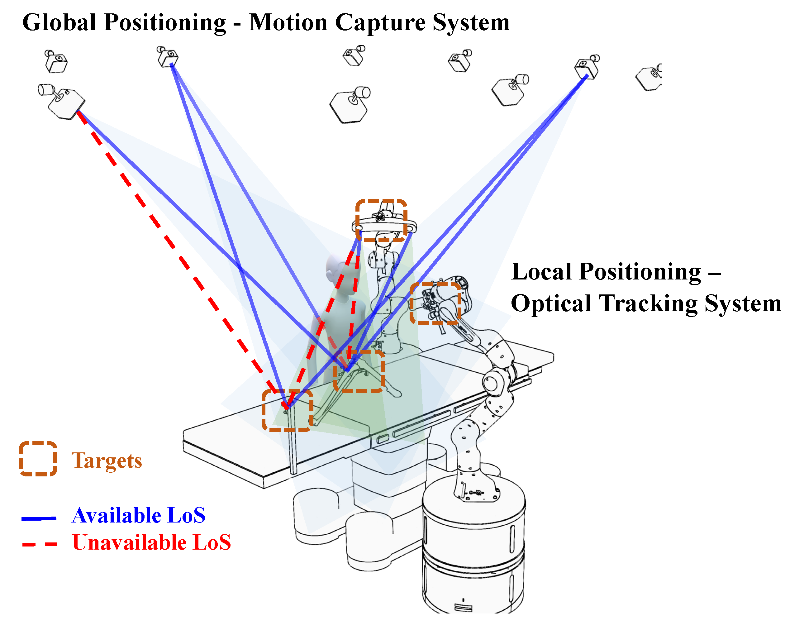
- We innovatively introduced the concept of a full-perception robotic surgery environment and established a global–local joint positioning framework;
- We enhanced positioning accuracy by integrating the biased Kalman filter algorithm with data characteristics;
- We devised an evaluation method based on the view margin model for assessing dynamic positioning accuracy, thereby demonstrating the superiority of our method.
3. Global-Local Positioning Method
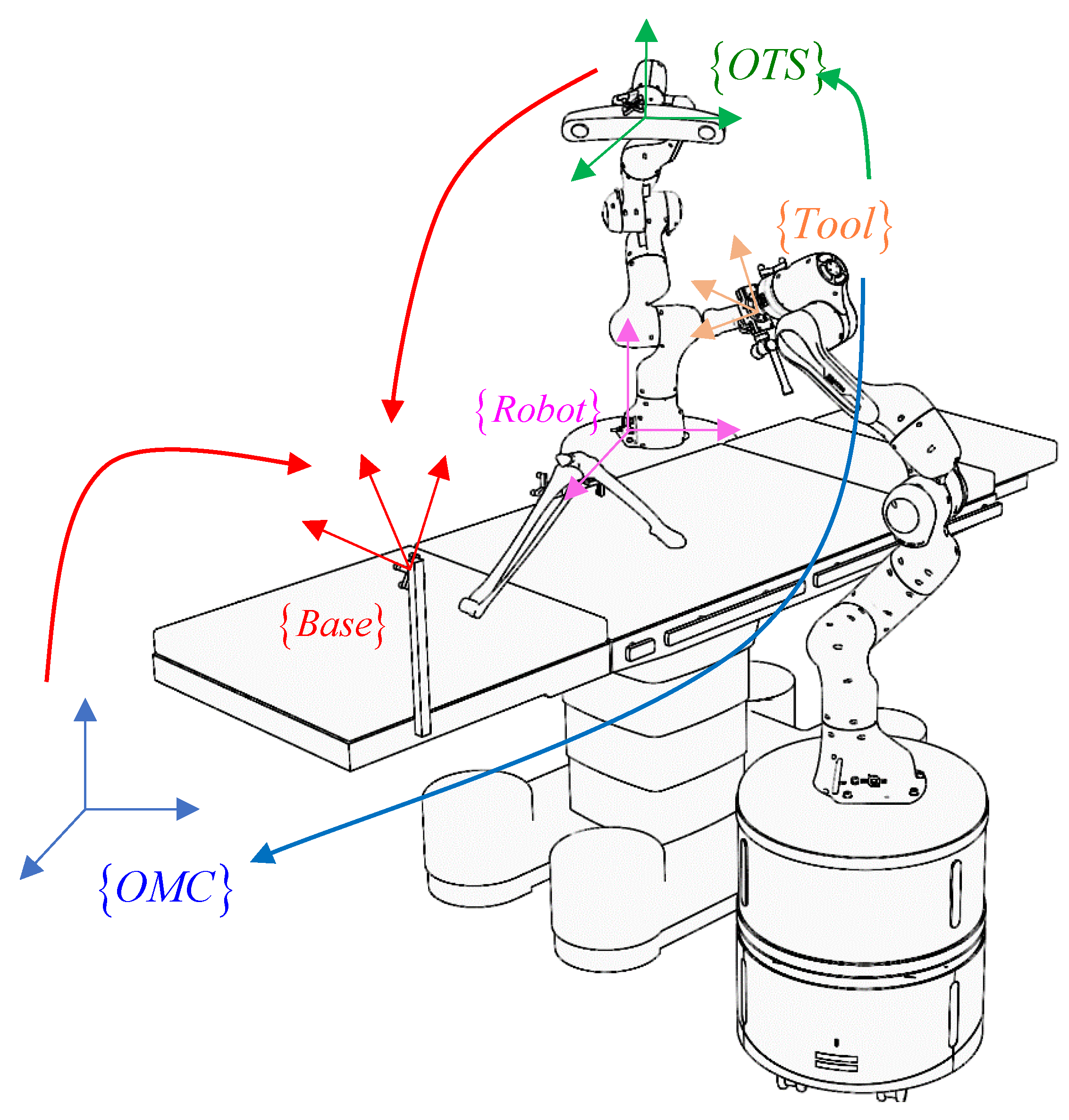
3.1. Unified Coordinate Expression
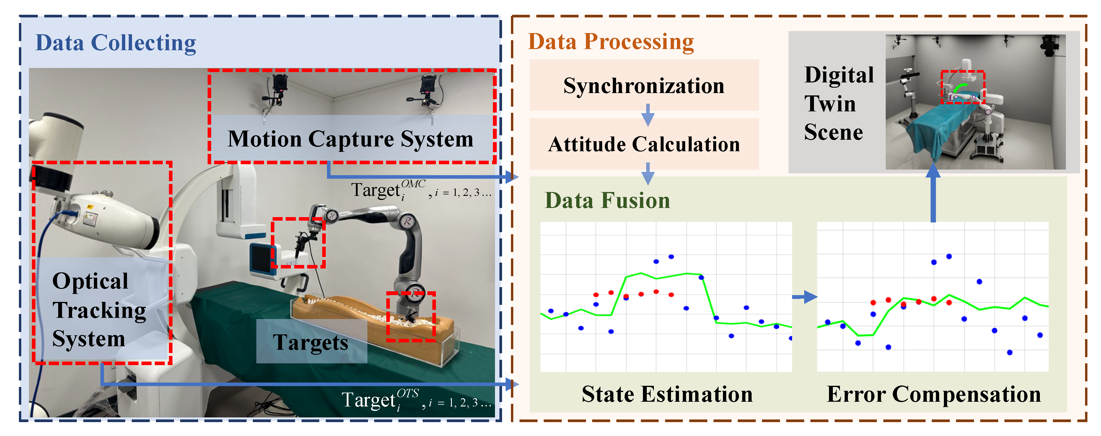
3.2. Data Fusion Method
4. Dynamic Positioning Evaluation Method for Full-Perception Surgery Scene
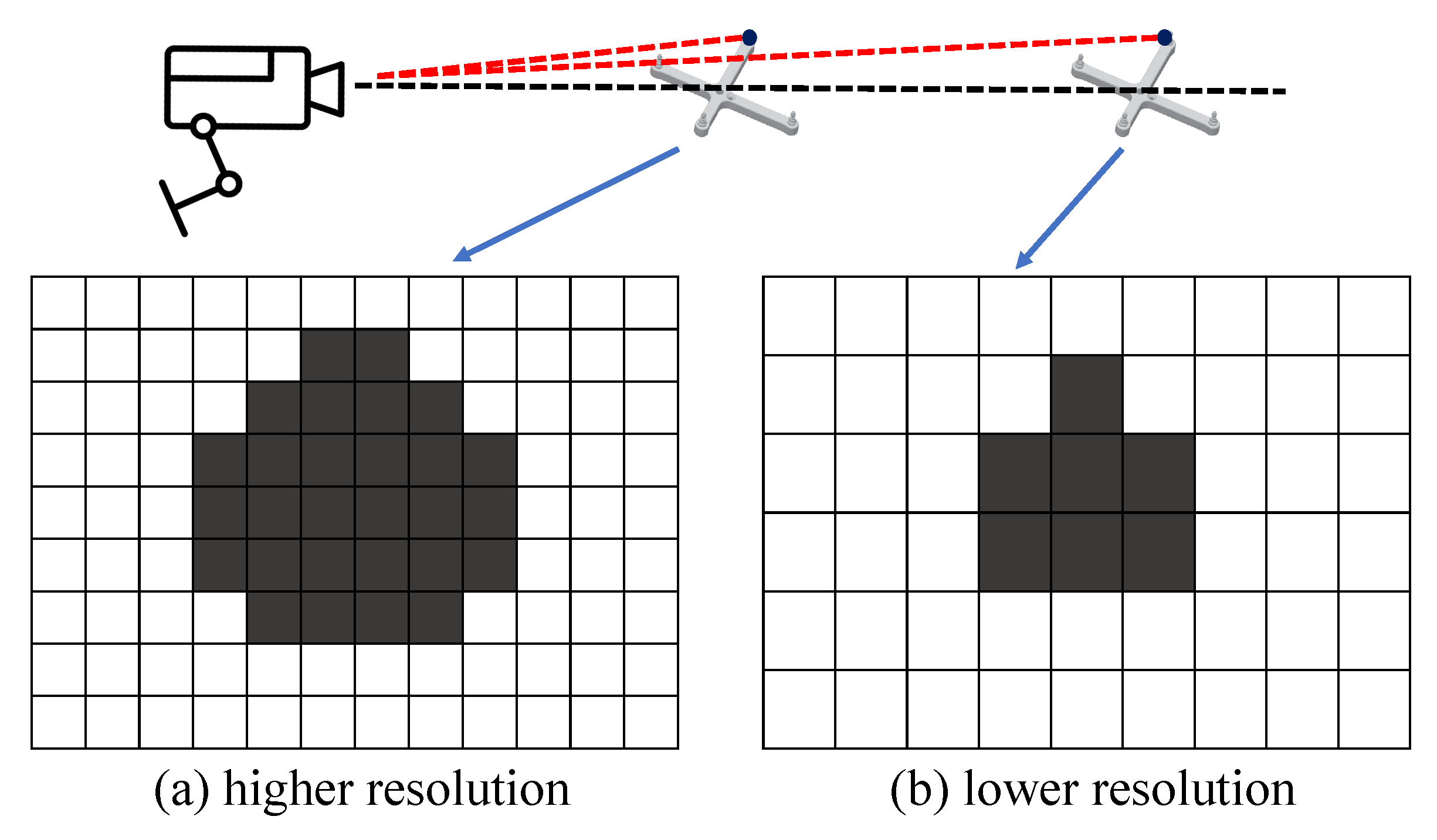
4.1. Static Factor Analysis
4.2. Dynamic Evaluation Method Based on View Margin Model
| Algorithm 1: View margin computation for a point in the region of interest |
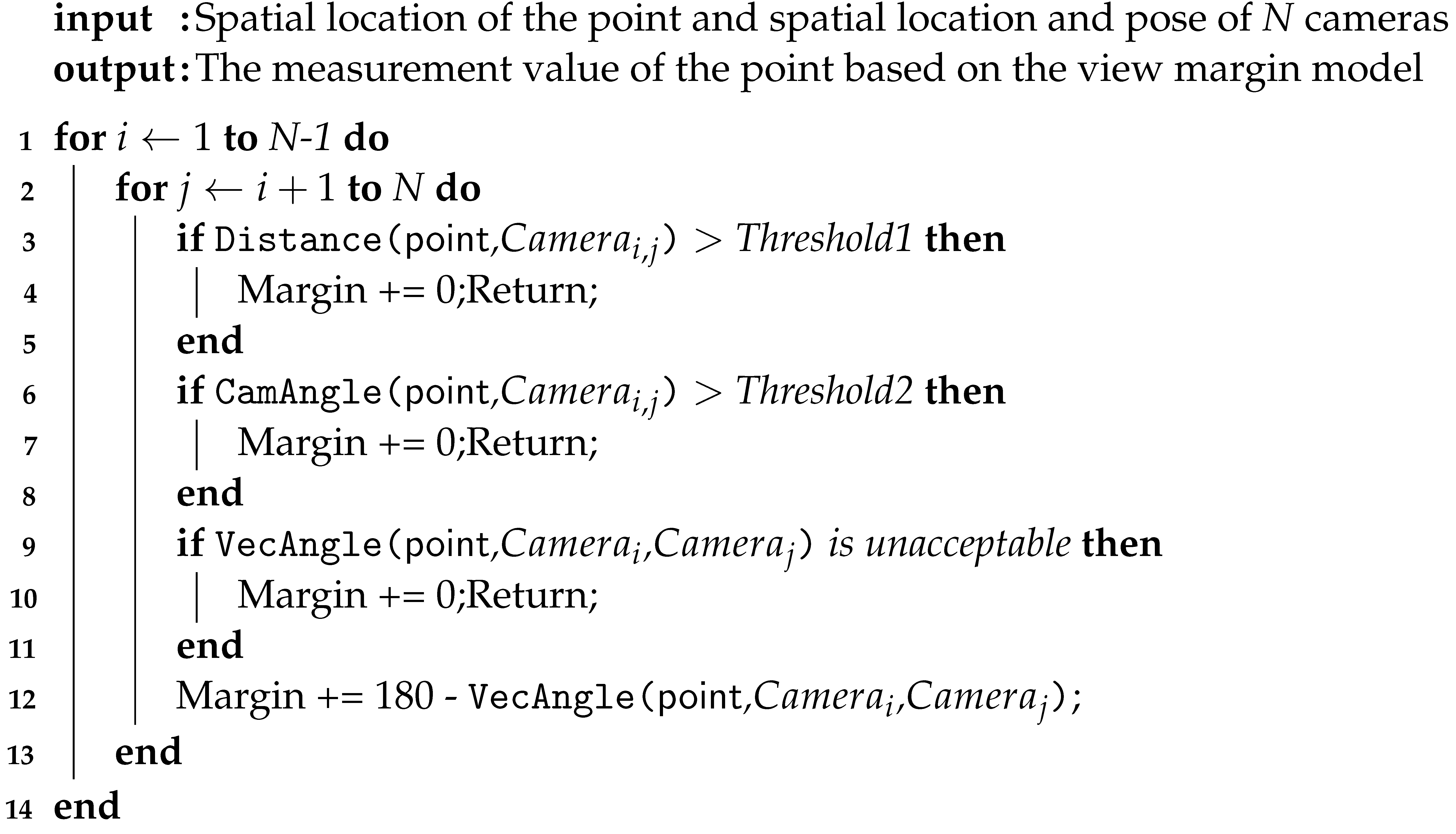 |
- Trajectory needs to complete the crossing of BVV, GVV, and PVV areas, and the output data of the positioning method are continuous during the crossing process;
- The location method should deal with the system deviation of the global positioning itself and the data hop caused by the movement in the PVV during the region switching process.
5. Experiments
5.1. System Setup
5.2. Dynamic Task Evaluation Methods and Results
6. Conclusions
Author Contributions
Funding
Institutional Review Board Statement
Informed Consent Statement
Data Availability Statement
Conflicts of Interest
Abbreviations
| OTS | Optical Tracking System |
| OMC | Optical Motion Capture |
References
- Maciunas, R.J.; Galloway, R.L., Jr.; Fitzpatrick, J.M.; Mandava, V.R.; Edwards, C.A.; Allen, G.S. A universal system for interactive image-directed neurosurgery. Ster. Funct Neurosurg. 1992, 58, 108–113. [Google Scholar] [CrossRef]
- Song, S.; Qiao, W.; Li, B.; Hu, C.; Ren, H.; Meng, M.Q.H. An Efficient Magnetic Tracking Method Using Uniaxial Sensing Coil. IEEE Trans. Magn. 2014, 50, 1–7. [Google Scholar] [CrossRef]
- Morris, A.; Dickinson, M.; Zalzala, A. An enhanced ultrasonic system for robot end effector tracking. In Proceedings of the International Conference on Control 1991, Control’91, Edinburgh, UK, 25–28 March 1991; pp. 352–357. [Google Scholar]
- He, Q.; Wei, N.; Li, B.; Hu, C.; Meng, M.H. Marker-based quadri-ocular tracking system for surgery. Proc. IET Comput. Vis. 2012, 6, 435–441. [Google Scholar] [CrossRef]
- Ren, H.; Liu, W.; Lim, A. Marker-based surgical instrument tracking using dual kinect sensors. IEEE Trans. Autom. Sci. Eng. 2013, 11, 921–924. [Google Scholar] [CrossRef]
- Wang, J.; Ren, H.; Meng, M.Q.H. A preliminary study on surgical instrument tracking based on multiple modules of monocular pose estimation. In Proceedings of the 4th Annual IEEE International Conference on Cyber Technology in Automation, Control and Intelligent, Hong Kong, China, 4–7 June 2014; pp. 146–151. [Google Scholar]
- Wiles, A.D.; Thompson, D.G.; Frantz, D.D. Accuracy assessment and interpretation for optical tracking systems. In Proceedings of the Medical Imaging 2004: Visualization, Image-Guided Procedures, and Display, San Diego, CA, USA, 14–19 February 2004; Volume 5367, pp. 421–432. [Google Scholar]
- Bauwens, K.; Matthes, G.; Wich, M.; Gebhard, F.; Hanson, B.; Ekkernkamp, A.; Stengel, D. Navigated total knee replacement: A meta-analysis. JBJS 2007, 89, 261–269. [Google Scholar] [CrossRef]
- Shamir, R.R.; Joskowicz, L.; Spektor, S.; Shoshan, Y. Localization and registration accuracy in image guided neurosurgery: A clinical study. Int. J. Comput. Assist. Radiol. Surg. 2009, 4, 45–52. [Google Scholar] [CrossRef] [PubMed]
- García-Vázquez, V.; Marinetto, E.; Santos-Miranda, J.; Calvo, F.; Desco, M.; Pascau, J. Feasibility of integrating a multi-camera optical tracking system in intra-operative electron radiation therapy scenarios. Phys. Med. Biol. 2013, 58, 8769. [Google Scholar] [CrossRef]
- Tran, D.T.; Sakurai, R.; Yamazoe, H.; Lee, J.H. PCA-based surgical phases estimation with a multi-camera system. In Proceedings of the 2017 14th International Conference on Ubiquitous Robots and Ambient Intelligence (URAI), Jeju, Republic of Korea, 28 June–1 July 2017; pp. 136–141. [Google Scholar]
- Murugesan, Y.P.; Alsadoon, A.; Manoranjan, P.; Prasad, P. A novel rotational matrix and translation vector algorithm: Geometric accuracy for augmented reality in oral and maxillofacial surgeries. Int. J. Med. Robot. Comput. Assist. Surg. 2018, 14, e1889. [Google Scholar] [CrossRef] [PubMed]
- Pfeiffer, J.H.; Borbáth, Á.; Dietz, C.; Lueth, T.C. A new module combining two tracking cameras to expand the workspace of surgical navigation systems. In Proceedings of the 2016 IEEE/SICE International Symposium on System Integration (SII), Sapporo, Japan, 13–15 December 2016; pp. 477–482. [Google Scholar]
- Wang, J.; Qi, L.; Meng, M.Q.H. Robot-assisted occlusion avoidance for surgical instrument optical tracking system. In Proceedings of the 2015 IEEE International Conference on Information and Automation, Lijiang, China, 8–10 August 2015; pp. 375–380. [Google Scholar]
- Tobergte, A.; Pomarlan, M.; Hirzinger, G. Robust multi sensor pose estimation for medical applications. In Proceedings of the 2009 IEEE/RSJ International Conference on Intelligent Robots and Systems, St. Louis, MO, USA, 10–15 October 2009; pp. 492–497. [Google Scholar]
- Kennedy-Metz, L.R.; Mascagni, P.; Torralba, A.; Dias, R.D.; Perona, P.; Shah, J.A.; Padoy, N.; Zenati, M.A. Computer vision in the operating room: Opportunities and caveats. IEEE Trans. Med. Rob. Bionics 2020, 3, 2–10. [Google Scholar] [CrossRef] [PubMed]
- Zenati, M.A.; Kennedy-Metz, L.; Dias, R.D. Cognitive engineering to improve patient safety and outcomes in cardiothoracic surgery. Semin. Thorac. Cardiovasc. Surg. 2020, 32, 1–7. [Google Scholar] [CrossRef]
- Gao, C.; Phalen, H.; Margalit, A.; Ma, J.H.; Ku, P.C.; Unberath, M.; Taylor, R.H.; Jain, A.; Armand, M. Fluoroscopy-Guided Robotic System for Transforaminal Lumbar Epidural Injections. IEEE Trans. Med. Robot. Bionics 2022, 4, 901–909. [Google Scholar] [CrossRef]
- Wang, H.; Wang, P. Clinical Study of Cervical Spine Motion Trajectory Based on Computer Motion Capture Technology. In Proceedings of the 2022 World Automation Congress (WAC), San Antonio, TX, USA, 11–15 October 2022; pp. 197–201. [Google Scholar]
- Carse, B.; Meadows, B.; Bowers, R.; Rowe, P. Affordable clinical gait analysis: An assessment of the marker tracking accuracy of a new low-cost optical 3D motion analysis system. Physiotherapy 2013, 99, 347–351. [Google Scholar] [CrossRef] [PubMed]
- Eichelberger, P.; Ferraro, M.; Minder, U.; Denton, T.; Blasimann, A.; Krause, F.; Baur, H. Analysis of accuracy in optical motion capture–A protocol for laboratory setup evaluation. J. Biomech. 2016, 49, 2085–2088. [Google Scholar] [CrossRef] [PubMed]
- Marinetto, E.; García-Mato, D.; GarcíA, A.; Martínez, S.; Desco, M.; Pascau, J. Multicamera optical tracker assessment for computer aided surgery applications. IEEE Access 2018, 6, 64359–64370. [Google Scholar] [CrossRef]
- Min, Z.; Zhu, D.; Meng, M.Q.H. Accuracy assessment of an N-ocular motion capture system for surgical tool tip tracking using pivot calibration. In Proceedings of the 2016 IEEE International Conference on Information and Automation (ICIA), Ningbo, China, 1–3 August 2016; pp. 1630–1634. [Google Scholar]
- Aurand, A.M.; Dufour, J.S.; Marras, W.S. Accuracy map of an optical motion capture system with 42 or 21 cameras in a large measurement volume. J. Biomech. 2017, 58, 237–240. [Google Scholar] [CrossRef]
- Meng, Y.; You, Y.; Geng, P.; Song, Z.; Wang, H.; Qin, Y. Development of an intra-operative active navigation system for robot-assisted surgery. In Proceedings of the 2021 IEEE International Conference on Robotics and Biomimetics (ROBIO), Sanya, China, 27–31 December 2021; pp. 1755–1760. [Google Scholar]
- Skurowski, P.; Pawlyta, M. On the noise complexity in an optical motion capture facility. Sensors 2019, 19, 4435. [Google Scholar] [CrossRef] [PubMed]
- Olague, G.; Mohr, R. Optimal camera placement for accurate reconstruction. Pattern Recognit. 2002, 35, 927–944. [Google Scholar] [CrossRef]
- Rahimian, P.; Kearney, J.K. Optimal camera placement for motion capture systems. IEEE Trans. Vis. Comput. Graph. 2016, 23, 1209–1221. [Google Scholar] [CrossRef]
- Tan, J.; Li, D.; Zhang, J.Q.; Hu, B.; Lu, Q. Biased Kalman filter. In Proceedings of the 2011 Fifth International Conference on Sensing Technology, Palmerston North, New Zealand, 28 November–1 December 2011; pp. 581–584. [Google Scholar]
- Wu, J.J.; Sharma, R.; Huang, T.S. Analysis of uncertainty bounds due to quantization for three-dimensional position estimation using multiple cameras. Opt. Eng. 1998, 37, 280–292. [Google Scholar]
- Chen, X.; Davis, J. An occlusion metric for selecting robust camera configurations. Mach. Vis. Appl. 2008, 19, 217–222. [Google Scholar] [CrossRef]
- Liu, Z.; Yang, D.; Wang, Y. EGNN: Graph structure learning based on evolutionary computation helps more in graph neural networks. Appl. Soft Comput. 2023, 135, 110040. [Google Scholar] [CrossRef]
- Jun, Z.; Lv, Y. Output-feedback Robust Tracking Control of Uncertain Systems via Adaptive Learning. Int. J. Control Autom. Syst. 2023, 21, 1108–1118. [Google Scholar]


| ID | Task | OMC | KF | BKF | CKF | CBKF (Ours) |
|---|---|---|---|---|---|---|
| 1 | G-B-P | 3.39 | 1.84 | 1.82 | 1.64 | 1.63 |
| 2 | P-G-B | 3.00 | 1.99 | 1.98 | 1.99 | 1.98 |
| 3 | P-G-B-P | 3.94 | 2.61 | 2.59 | 1.85 | 1.85 |
| 4 | P-B-G | 3.79 | 2.02 | 2.02 | 2.02 | 2.02 |
| 5 | B-G-P | 3.79 | 2.14 | 2.13 | 1.82 | 1.82 |
| 6 | P-B-G-P | 3.81 | 2.21 | 2.20 | 1.77 | 1.76 |
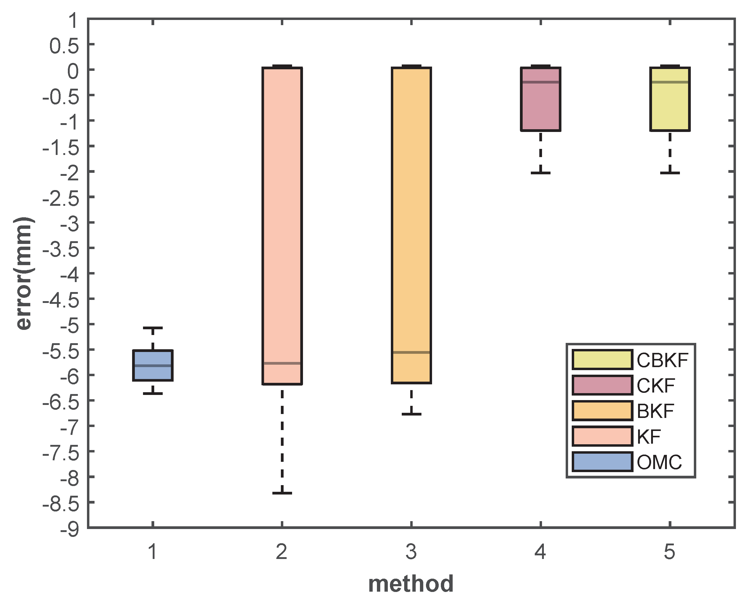
| Value | OMC | KF | BKF | CKF | CBKF (Ours) |
|---|---|---|---|---|---|
| max | 6.36 | 8.32 | 6.76 | 2.02 | 2.02 |
| median | 5.81 | 5.77 | 5.56 | 0.25 | 0.25 |
Disclaimer/Publisher’s Note: The statements, opinions and data contained in all publications are solely those of the individual author(s) and contributor(s) and not of MDPI and/or the editor(s). MDPI and/or the editor(s) disclaim responsibility for any injury to people or property resulting from any ideas, methods, instructions or products referred to in the content. |
© 2023 by the authors. Licensee MDPI, Basel, Switzerland. This article is an open access article distributed under the terms and conditions of the Creative Commons Attribution (CC BY) license (https://creativecommons.org/licenses/by/4.0/).
Share and Cite
Wang, H.; Liu, T.; Chen, J.; Fan, C.; Qin, Y.; Han, J. Full-Perception Robotic Surgery Environment with Anti-Occlusion Global–Local Joint Positioning. Sensors 2023, 23, 8637. https://doi.org/10.3390/s23208637
Wang H, Liu T, Chen J, Fan C, Qin Y, Han J. Full-Perception Robotic Surgery Environment with Anti-Occlusion Global–Local Joint Positioning. Sensors. 2023; 23(20):8637. https://doi.org/10.3390/s23208637
Chicago/Turabian StyleWang, Hongpeng, Tianzuo Liu, Jianren Chen, Chongshan Fan, Yanding Qin, and Jianda Han. 2023. "Full-Perception Robotic Surgery Environment with Anti-Occlusion Global–Local Joint Positioning" Sensors 23, no. 20: 8637. https://doi.org/10.3390/s23208637
APA StyleWang, H., Liu, T., Chen, J., Fan, C., Qin, Y., & Han, J. (2023). Full-Perception Robotic Surgery Environment with Anti-Occlusion Global–Local Joint Positioning. Sensors, 23(20), 8637. https://doi.org/10.3390/s23208637