
Split Ring Antennas and Their Application for Antenna Miniaturization


Abstract
1. Introduction
2. Antenna Configuration
2.1. 3-Dimensional Split Ring Array
2.2. Arrays with Modified Split Ring Geometries
3. Fabrication and Measurement
4. Conclusions
Author Contributions
Funding
Data Availability Statement
Acknowledgments
Conflicts of Interest
References
- Chu, L.J. Physical Limitations of Omni-Directional Antennas. J. Appl. Phys. 1948, 19, 1163–1175. [Google Scholar] [CrossRef]
- Wheeler, H. Small antennas. IEEE Trans. Antennas Propag. 1975, 23, 462–469. [Google Scholar] [CrossRef]
- Chen, L.; Ma, Q.; Luo, S.S.; Ye, F.J.; Cui, H.Y.; Cui, T.J. Touch-Programmable Metasurface for Various Electromagnetic Manipulations and Encryptions. Small 2022, 18, e2203871. [Google Scholar] [CrossRef] [PubMed]
- Ma, Q.; Bai, G.D.; Jing, H.B.; Yang, C.; Li, L.; Cui, T.J. Smart metasurface with self-adaptively reprogrammable functions. Light-Sci. Appl. 2019, 8, 98. [Google Scholar] [CrossRef] [PubMed]
- Ma, Q.; Gao, W.; Xiao, Q.; Ding, L.; Gao, T.; Zhou, Y.; Gao, X.; Yan, T.; Liu, C.; Gu, Z.; et al. Directly wireless communication of human minds via non-invasive brain-computer-metasurface platform. arXiv 2022, arXiv:2205.00280. [Google Scholar] [CrossRef]
- Mongia, R.K.; Ittibipoon, A.; Cuhaci, M. Low profile dielectric resonator antennas using a very high permittivity material. Electron. Lett. 1994, 30, 1362–1363. [Google Scholar] [CrossRef]
- Aligodarz, M.T.; Klymyshyn, D.M.; Rashidian, A.; Borner, M.; Shafai, L.; Mohr, J. Investigations on Photoresist-Based Artificial Dielectrics with Tall-Embedded Metal Grids and Their Resonator Antenna Application. IEEE Trans. Antennas Propag. 2015, 63, 3826–3838. [Google Scholar] [CrossRef]
- Mongia, R.K. Reduced size metallized dielectric resonator antennas. In Proceedings of the IEEE Antennas and Propagation Society International Symposium 1997 Digest, Montreal, QC, Canada, 13–18 July 1997. [Google Scholar]
- Lee, M.T.; Luk, K.M.; Leung, K.W.; Leung, M.K. A small dielectric resonator antenna. IEEE Trans. Antennas Propag. 2002, 50, 1485–1487. [Google Scholar] [CrossRef]
- O’Keefe, S.G.; Kingsley, S.P.; Saario, S. FDTD simulation of radiation characteristics of half-volume HEM-and TE-mode dielectric resonator antennas. IEEE Trans. Antennas Propag. 2002, 50, 175–179. [Google Scholar] [CrossRef]
- Rashidian, A.; Klymyshyn, D.M. On the Two Segmented and High Aspect Ratio Rectangular Dielectric Resonator Antennas for Bandwidth Enhancement and Miniaturization. IEEE Trans. Antennas Propag. 2009, 57, 2775–2780. [Google Scholar] [CrossRef]
- Rashidian, A.; Shafai, L.; Shafai, C. Miniaturized Transparent Metallodielectric Resonator Antennas Integrated with Amorphous Silicon Solar Cells. IEEE Trans. Antennas Propag. 2017, 65, 2265–2275. [Google Scholar] [CrossRef]
- Gotra, S.; Varshney, G.; Yaduvanshi, R.; Pandey, V. Dual-band circular polarisation generation technique with the miniaturisation of a rectangular dielectric resonator antenna. IET Microw. Antennas Propag. 2019, 13, 1742–1748. [Google Scholar] [CrossRef]
- Hansen, R.C.; Burke, M. Antennas with magneto-dielectrics. Microw. Opt. Technol. Lett. 2000, 26, 75–78. [Google Scholar] [CrossRef]
- Ikonen, P.; Tretyakov, S. On the advantages of magnetic materials in microstrip antenna miniaturization. Microw. Opt. Technol. Lett. 2008, 50, 3131–3134. [Google Scholar] [CrossRef]
- Buell, K.; Mosallaei, H.; Sarabandi, K. A substrate for small patch antennas providing tunable miniaturization factors. IEEE Trans. Microw. Theory Tech. 2006, 54, 135–146. [Google Scholar] [CrossRef]
- Liu, Y.; Raju, R.; Shafai, L.; Shafai, C. A miniaturized artificial magneto-dielectric resonator antenna with split ring resonators. In Proceedings of the 2016 17th International Symposium on Antenna Technology and Applied Electromagnetics (ANTEM), Montreal, QC, Canada, 10–13 July 2016. [Google Scholar]
- Kao, K.C. Dielectric Phenomena in Solids; Elsevier Academic Press: San Diego, CA, USA, 2004. [Google Scholar] [CrossRef]
- Smith, D.R. Novel Electromagnetic Media. Available online: http://people.ee.duke.edu/~drsmith/metamaterials/metamaterial_elements.htm (accessed on 1 July 2017).
- Lewin, W. Lec 21: Magnetic Materials|8.02 Electricity and Magnetism. Spring 2002. Available online: https://www.youtube.com/watch?v=TJGRatHJgEI (accessed on 1 July 2017).
- Pendry, J.B.; Holden, A.J.; Robbins, D.J.; Stewart, W.J. Magnetism from conductors and enhanced nonlinear phenomena. IEEE Trans. Microw. Theory Tech. 1999, 47, 2075–2084. [Google Scholar] [CrossRef]
- Bilotti, F.; Toscano, A.; Vegni, L. Design of Spiral and Multiple Split-Ring Resonators for the Realization of Miniaturized Metamaterial Samples. IEEE Trans. Antennas Propag. 2007, 55, 2258–2267. [Google Scholar] [CrossRef]
- Mongia, R.K.; Ittipiboon, A. Theoretical and experimental investigations on rectangular dielectric resonator antennas. IEEE Trans. Antennas Propag. 1997, 45, 1348–1356. [Google Scholar] [CrossRef]
- Liu, Y.; Shafai, L.; Shafai, C. Effects of Split Ring Arrangement and Slit location on the Miniaturization Performance of Split Ring Loaded Dielectric Resonator Antennas. In Proceedings of the 2017 XXXIInd General Assembly and Scientific Symposium of the International Union of Radio Science (URSI GASS), Montreal, QC, Canada, 19–26 August 2017. [Google Scholar]
- Hsu, W.H.; Wong, K.L. Broadband probe-fed patch antenna with a U-shaped ground plane for cross-polarization reduction. IEEE Trans. Antennas Propag. 2002, 50, 352–355. [Google Scholar] [CrossRef]
- Liu, Y. Gain and Efficiency Enhancement of the Miniaturized Split Ring Based Antennas. M.Sc. Thesis, University of Manitoba, Winnipeg, MB, Canada, 2017. [Google Scholar]
- Liu, Y.; Shafai, L.; Shafai, C. Probe-fed Rectangular Flat-wire Open Loop Antennas. In Proceedings of the 2018 18th International Symposium on Antenna Technology and Applied Electromagnetics (ANTEM), Waterloo, ON, Canada, 19–22 August 2018. [Google Scholar]
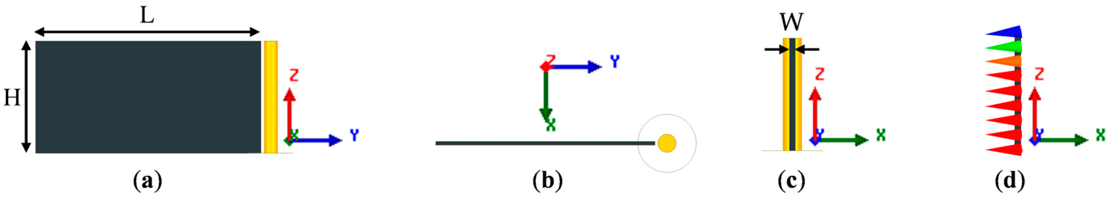
 Host substrate,
  Probe); (b) Top view; (c) Left side view; (d) Excitation magnetic field in the substrate. (Ground plane not shown in all four sub-figures, and probe not shown in (d)).
Host substrate, Probe); (b) Top view; (c) Left side view; (d) Excitation magnetic field in the substrate. (Ground plane not shown in all four sub-figures, and probe not shown in (d)).
Probe); (b) Top view; (c) Left side view; (d) Excitation magnetic field in the substrate. (Ground plane not shown in all four sub-figures, and probe not shown in (d)).
Host substrate, Probe); (b) Top view; (c) Left side view; (d) Excitation magnetic field in the substrate. (Ground plane not shown in all four sub-figures, and probe not shown in (d)).
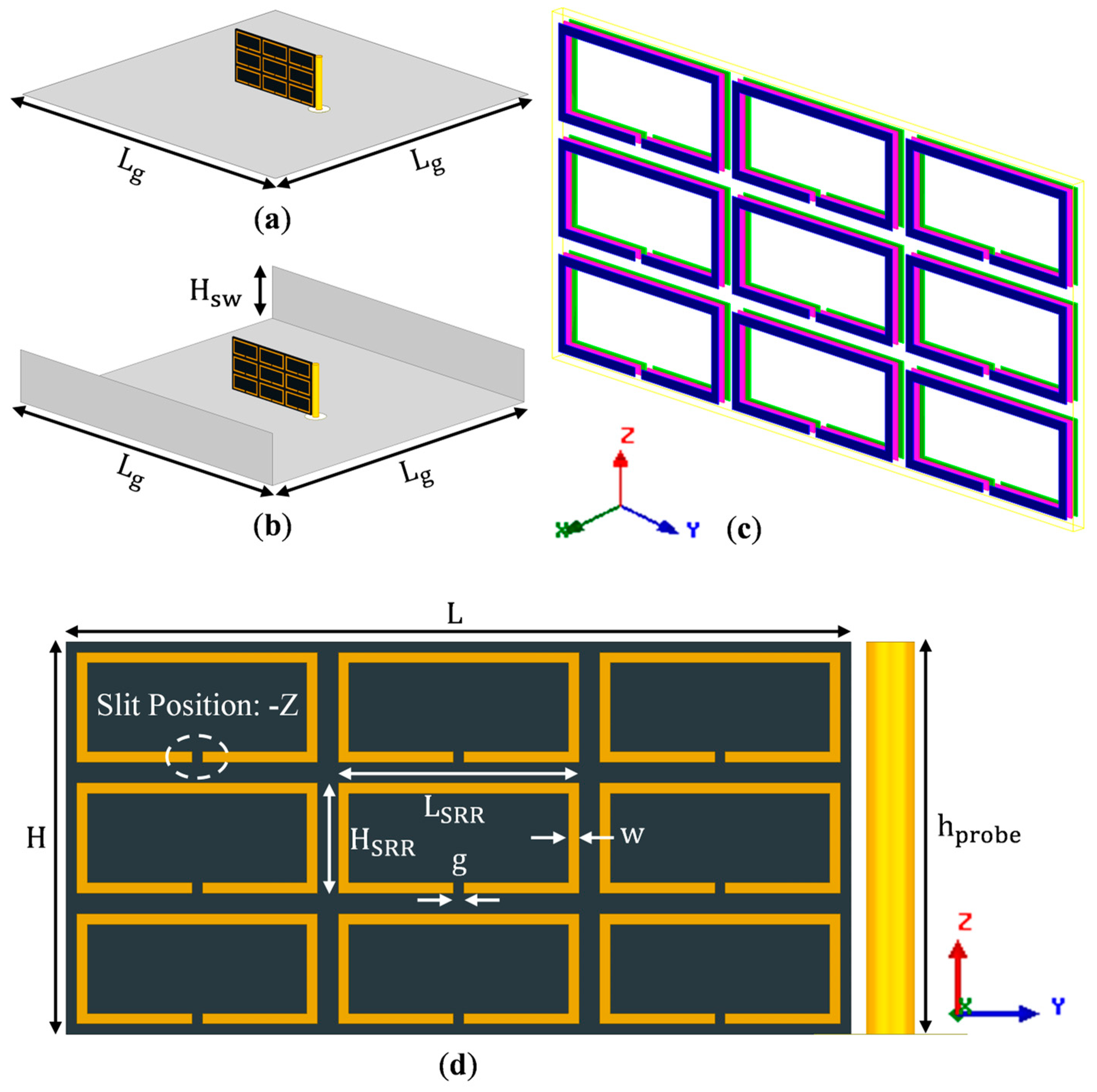
 Host substrate;
  SRRs and probe;
  Ground plane). (b) Oblique view of the same antenna on a U-shaped ground plane. (c) Zoomed-in view of the ring arrangements on the substrate (different colors are used to demonstrate different layers of SRRs). The three identical layers of SRRs are placed on the front (
 blue), center (
 pink), and back (
 green) surfaces. (d) Zoomed-in front view of the SRR array with dimensions as marked.
Host substrate; SRRs and probe; Ground plane). (b) Oblique view of the same antenna on a U-shaped ground plane. (c) Zoomed-in view of the ring arrangements on the substrate (different colors are used to demonstrate different layers of SRRs). The three identical layers of SRRs are placed on the front ( blue), center ( pink), and back ( green) surfaces. (d) Zoomed-in front view of the SRR array with dimensions as marked.
green) surfaces. (d) Zoomed-in front view of the SRR array with dimensions as marked.
Host substrate; SRRs and probe; Ground plane). (b) Oblique view of the same antenna on a U-shaped ground plane. (c) Zoomed-in view of the ring arrangements on the substrate (different colors are used to demonstrate different layers of SRRs). The three identical layers of SRRs are placed on the front ( blue), center ( pink), and back ( green) surfaces. (d) Zoomed-in front view of the SRR array with dimensions as marked.
 ,
,  ,
,  ,
,  ,
,  ,
,  .
, , , , , .
.
, , , , , . Host substrate (L = 15 mm, H = 7.5 mm);
  Modified SRRs. Ground plane and probe are not shown.
Host substrate (L = 15 mm, H = 7.5 mm); Modified SRRs. Ground plane and probe are not shown.
Modified SRRs. Ground plane and probe are not shown.
Host substrate (L = 15 mm, H = 7.5 mm); Modified SRRs. Ground plane and probe are not shown.

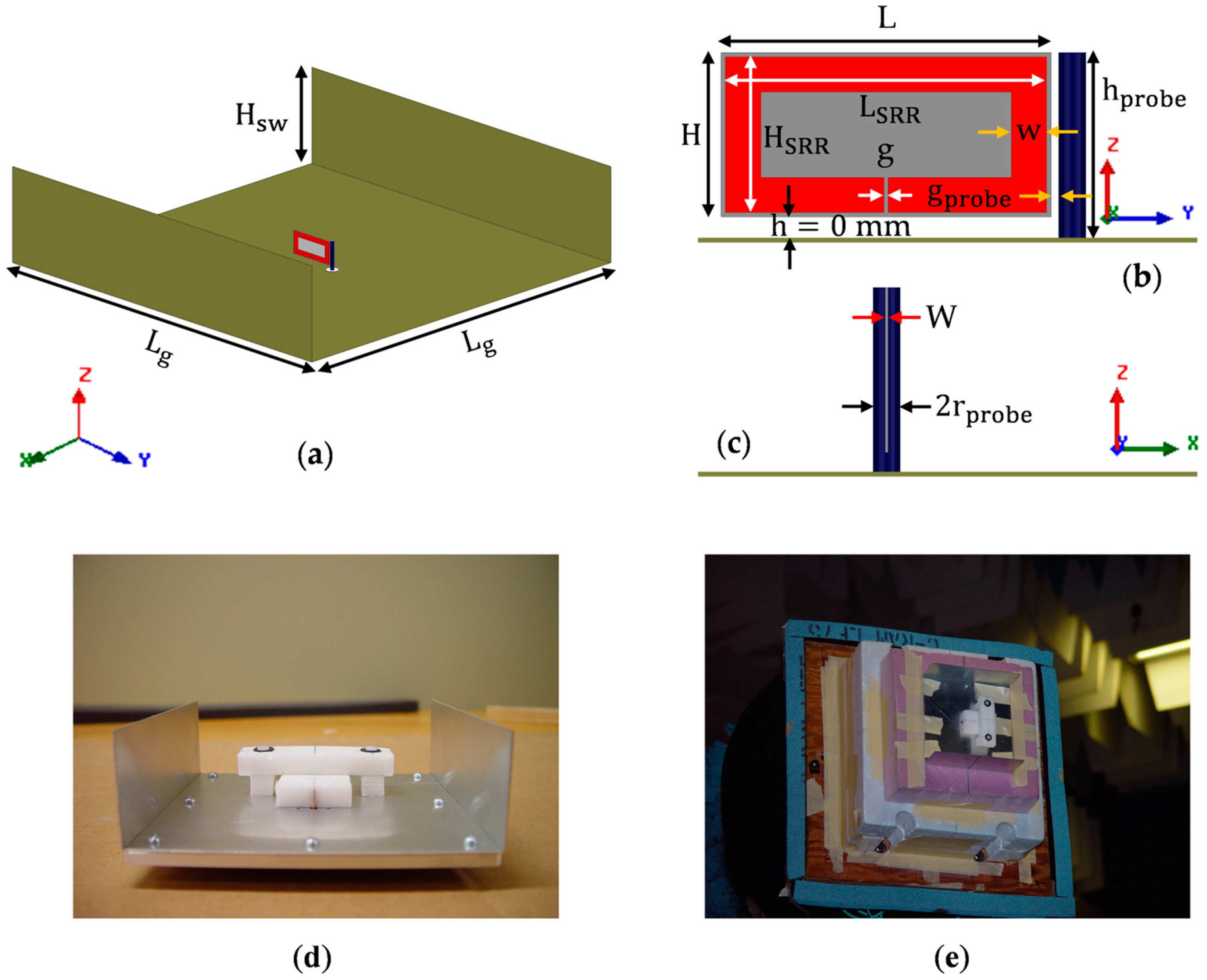
 Host substrate;
  SRR;
SRR;  Probe;
  Ground plane. (a) Oblique, (b) front and (c) side views of the simulated antenna. (d) Oblique view of the fabricated antenna and (e) the fabricated antenna under test, mounted on the tower.
Host substrate; SRR; Probe; Ground plane. (a) Oblique, (b) front and (c) side views of the simulated antenna. (d) Oblique view of the fabricated antenna and (e) the fabricated antenna under test, mounted on the tower.
Ground plane. (a) Oblique, (b) front and (c) side views of the simulated antenna. (d) Oblique view of the fabricated antenna and (e) the fabricated antenna under test, mounted on the tower.
Host substrate; SRR; Probe; Ground plane. (a) Oblique, (b) front and (c) side views of the simulated antenna. (d) Oblique view of the fabricated antenna and (e) the fabricated antenna under test, mounted on the tower.


| Host Substrate Dimensions (mm) | Excitation Dimensions (mm) | Host Substrate Properties | ||||||
|---|---|---|---|---|---|---|---|---|
| L | H | W | tan | |||||
| 15 | 7.5 | 0.254 | 7.5 | 0.625 | 2 | 2.2 | 1 | 0.0009 |
| Arrangement | Geometry (Front View) |  | (mm) | (mm) | (mm) | (mm) | (mm2) | (mm) |
|---|---|---|---|---|---|---|---|---|
 | 5 | 2.5 | 4.6 | 2.1 | 225.72 | 12.4 | ||
 | 5 | 3.75 | 4.6 | 3.35 | 249.48 | 14.9 | ||
 | 5 | 7.5 | 4.6 | 7.1 | 273.24 | 22.4 | ||
 | 7.5 | 3.75 | 7.1 | 3.35 | 260.82 | 19.9 | ||
 | 7.5 | 7.5 | 7.1 | 7.1 | 285.66 | 27.4 | ||
 | 15 | 7.5 | 14.6 | 7.1 | 298.08 | 42.4 | ||
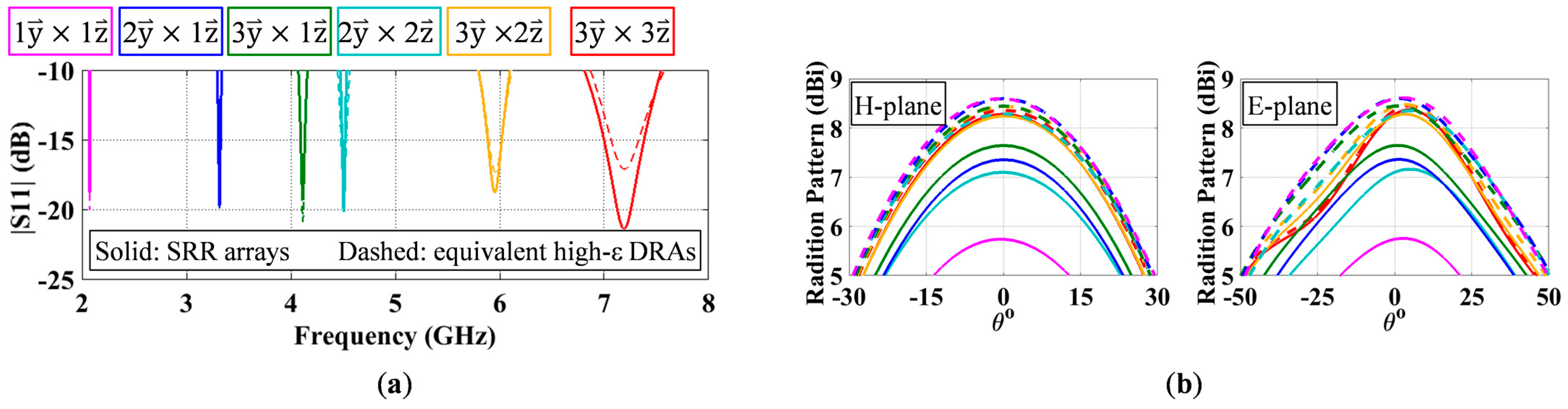
| Arrangement | (GHz) | BW (%) | (%) | (dBi) | X-Pol (dB) | Dir (dBi) | MC | ||
|---|---|---|---|---|---|---|---|---|---|
| Cal. 1 | Sim. 2 | ||||||||
| 7.1902 | 10.26 | 98.17 | 8.37 | −18.36 | 8.45 | 91.5 | 90.0 | 6.40 | |
| 5.9528 | 5.09 | 95.57 | 8.28 | −21.14 | 8.48 | 140.2 | 143.7 | 8.08 | |
| 4.1136 | 2.11 | 83.15 | 7.65 | −26.83 | 8.45 | 308.9 | 335.5 | 12.35 | |
| 4.5063 | 1.38 | 76.04 | 7.26 | −21.84 | 8.45 | 255.1 | 273.8 | 11.16 | |
| 3.3161 | 1.34 | 75.14 | 7.36 | −28.12 | 8.60 | 482.5 | 536.5 | 15.62 | |
| 2.0729 | 0.69 | 51.77 | 5.74 | −27.25 | 8.60 | 1255.5 | 1435.0 | 25.54 | |
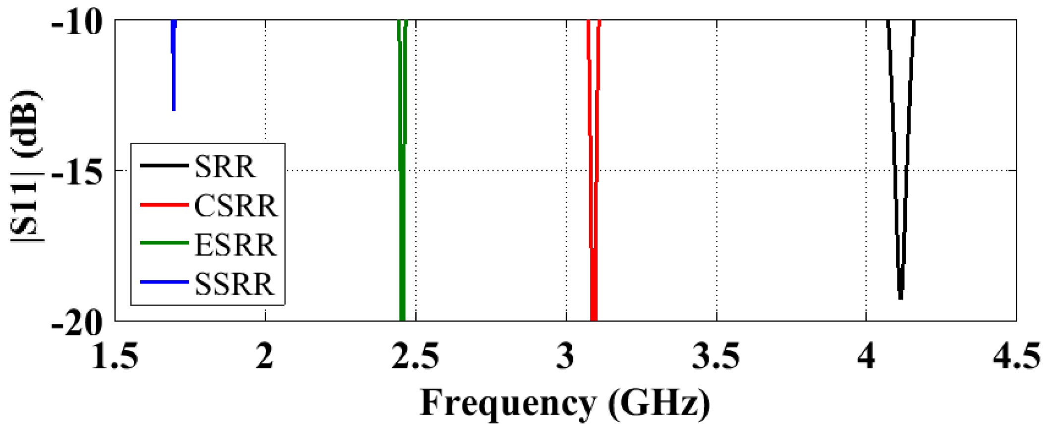
| Inclusions | w (mm) | g (mm) | (GHz) | BW (%) | (%) | (dBi) | X-Pol (dB) | (dBi) |
|---|---|---|---|---|---|---|---|---|
| SRR | 0.2 | 0.2 | 4.1136 | 2.11 | 83.15 | 7.65 | −26.83 | 8.45 |
| CSRR | 0.2 | 0.2 | 3.0925 | 1.16 | 69.25 | 6.60 | −26.55 | 8.20 |
| 0.5 | 0.2 | 3.5235 | 0.70 | 70.53 | 6.58 | −28.22 | 8.10 | |
| 0.5 | 0.8 | 3.6612 | 0.66 | 69.51 | 6.34 | −27.34 | 7.92 | |
| ESRR | 0.2 | 0.2 | 2.4570 | 0.88 | 41.01 | 4.25 | −26.81 | 8.12 |
| 0.5 | 0.2 | 2.6924 | 0.65 | 55.61 | 5.63 | −28.67 | 8.18 | |
| 0.5 | 0.8 | 3.6730 | 0.67 | 62.90 | 5.98 | −26.63 | 7.99 | |
| SSRR | 0.2 | 0.2 | 1.6959 | 0.38 | 17.42 | 0.86 | −32.19 | 8.45 |
| 0.5 | 0.2 | 2.0710 | 0.42 | 25.50 | 2.53 | −32.70 | 8.47 | |
| 0.5 | 0.8 | 2.2059 | 0.49 | 40.50 | 4.44 | −32.29 | 8.40 |
| Host Substrate (mm) | SRR (mm) | Probe (mm) | Air Gap (mm) | Ground Plane (mm) | ||||||||
|---|---|---|---|---|---|---|---|---|---|---|---|---|
| L | H | W | w | g | ||||||||
| 15 | 7.5 | 0.127 | 14.6 | 7.1 | 1.6 | 0.2 | 0.625 | 7.5 | 0.35 | 0 | 124 | 40 |
Disclaimer/Publisher’s Note: The statements, opinions and data contained in all publications are solely those of the individual author(s) and contributor(s) and not of MDPI and/or the editor(s). MDPI and/or the editor(s) disclaim responsibility for any injury to people or property resulting from any ideas, methods, instructions or products referred to in the content. |
© 2023 by the authors. Licensee MDPI, Basel, Switzerland. This article is an open access article distributed under the terms and conditions of the Creative Commons Attribution (CC BY) license (https://creativecommons.org/licenses/by/4.0/).
Share and Cite
Liu, Y.; Shafai, L.; Isleifson, D.; Shafai, C. Split Ring Antennas and Their Application for Antenna Miniaturization. Sensors 2023, 23, 846. https://doi.org/10.3390/s23020846
Liu Y, Shafai L, Isleifson D, Shafai C. Split Ring Antennas and Their Application for Antenna Miniaturization. Sensors. 2023; 23(2):846. https://doi.org/10.3390/s23020846
Chicago/Turabian StyleLiu, Yanxia, Lotfollah Shafai, Dustin Isleifson, and Cyrus Shafai. 2023. "Split Ring Antennas and Their Application for Antenna Miniaturization" Sensors 23, no. 2: 846. https://doi.org/10.3390/s23020846
APA StyleLiu, Y., Shafai, L., Isleifson, D., & Shafai, C. (2023). Split Ring Antennas and Their Application for Antenna Miniaturization. Sensors, 23(2), 846. https://doi.org/10.3390/s23020846