
TAKEN: A Traffic Knowledge-Based Navigation System for Connected and Autonomous Vehicles

 ,
,  ,
,  and
and 
Abstract
1. Introduction
2. Related Work
3. TAKEN-Traffic Knowledge-Based Navigation for CAVs
3.1. Traffic Knowledge Generation-Analysis Module
3.1.1. Waypoints and Velocity Generator
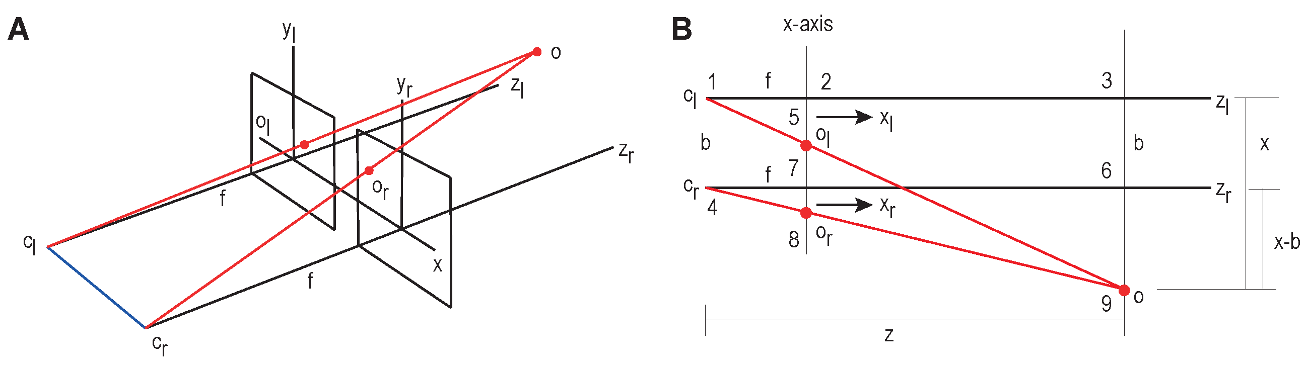
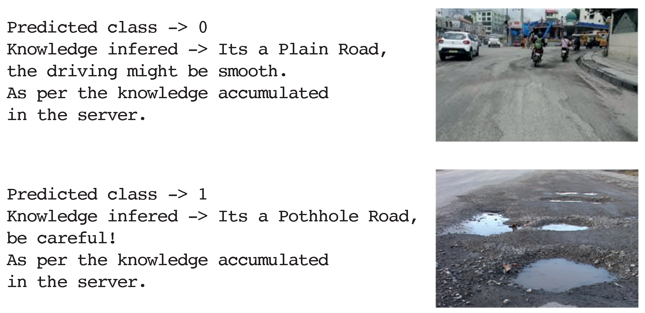
3.1.2. Visual Perception
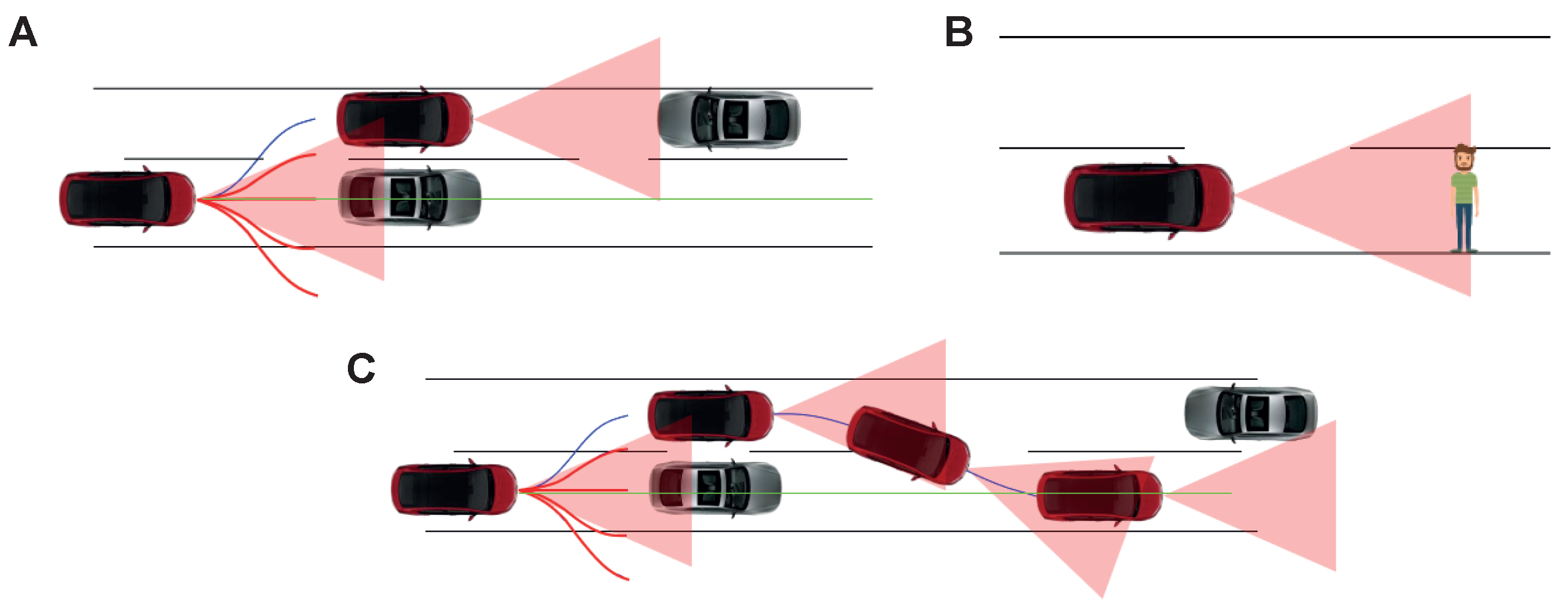
3.1.3. Low-Level Decision Making
3.2. Knowledge Sharing
3.3. CAV Controllers
4. Experiments
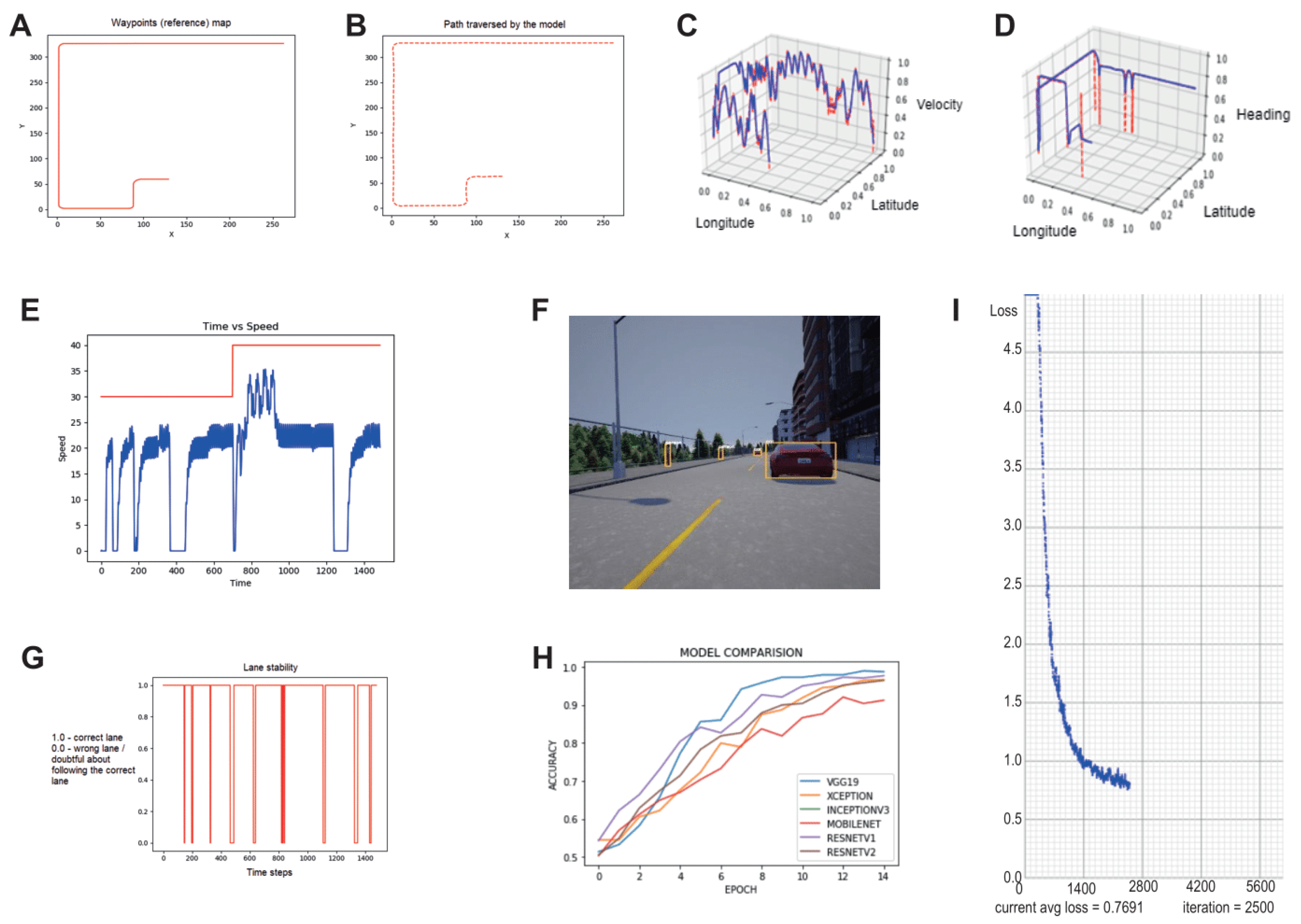
5. Results
6. Conclusions
Author Contributions
Funding
Institutional Review Board Statement
Informed Consent Statement
Data Availability Statement
Acknowledgments
Conflicts of Interest
Abbreviations
| CAV | Connected and Autonomous Vehicle |
| TAKEN | A Traffic Knowledge-based Navigation System for Connected and Autonomous Vehicles |
| SDC | Self Driving Car |
References
- Tan, Z.; Dai, N.; Su, Y.; Zhang, R.; Li, Y.; Wu, D.; Li, S. Human-machine interaction in intelligent and connected vehicles: A review of status quo, issues and opportunities. IEEE Trans. Intell. Transp. Syst. 2021, 23, 1–22. [Google Scholar] [CrossRef]
- Dhawankar, P.; Agrawal, P.; Abderezzak, B.; Kaiwartya, O.; Busawon, K.; Raboaca, M.S. Design and numerical implementation of v2x control architecture for autonomous driving vehicles. Mathematics 2021, 9, 1696. [Google Scholar] [CrossRef]
- Kaiwartya, O.; Abdullah, A.H.; Cao, Y.; Altameem, A.; Prasad, M.; Lin, C.-T.; Liu, X. Internet of vehicles: Motivation, layered architecture, network model, challenges, and future aspects. IEEE Access 2016, 4, 5356–5373. [Google Scholar] [CrossRef]
- Gao, Y.; Jing, H.; Dianati, M.; Hancock, C.M.; Meng, X. Performance analysis of robust cooperative positioning based on gps/uwb integration for connected autonomous vehicles. IEEE Trans. Intell. Veh. 2022, 1. [Google Scholar] [CrossRef]
- Kaiwartya, O.; Cao, Y.; Lloret, J.; Kumar, S.; Aslam, N.; Kharel, R.; Abdullah, A.H.; Shah, R.R. Geometry-based localization for gps outage in vehicular cyber physical systems. IEEE Trans. Veh. Technol. 2018, 67, 3800–3812. [Google Scholar] [CrossRef]
- Kumar, N.; Chaudhry, R.; Kaiwartya, O.; Kumar, N.; Ahmed, S.H. Green computing in software defined social internet of vehicles. IEEE Trans. Intell. Transp. Syst. 2020, 22, 3644–3653. [Google Scholar] [CrossRef]
- Mushtaq, A.; Haq, I.U.; Imtiaz, M.U.; Khan, A.; Shafiq, O. Traffic flow management of autonomous vehicles using deep reinforcement learning and smart rerouting. IEEE Access 2021, 9, 51005–51019. [Google Scholar] [CrossRef]
- Menelaou, C.; Timotheou, S.; Kolios, P.; Panayiotou, C.G.; Polycarpou, M.M. Minimizing traffic congestion through continuous-time route reservations with travel time predictions. IEEE Trans. Intell. Veh. 2018, 4, 141–153. [Google Scholar] [CrossRef]
- GOV.UK. Connected and Automated Vehicles: Market Forecast 2020. January 2021. Available online: https://www.gov.uk/government/publications/connected-and-automated-vehicles-market-forecast-2020 (accessed on 20 May 2022).
- Makarfi, A.U.; Rabie, K.M.; Kaiwartya, O.; Adhikari, K.; Nauryzbayev, G.; Li, X.; Kharel, R. Toward physical-layer security for internet of vehicles: Interference-aware modeling. IEEE Internet Things J. 2020, 8, 443–457. [Google Scholar] [CrossRef]
- Kaiser, M.S.; Lwin, K.T.; Mahmud, M.; Hajializadeh, D.; Chaipimonplin, T.; Sarhan, A.; Hossain, M.A. Advances in crowd analysis for urban applications through urban event detection. IEEE Trans. Intell. Transp. Syst. 2017, 19, 3092–3112. [Google Scholar] [CrossRef]
- Piazzi, A.; Bianco, C.L.; Bertozzi, M.; Fascioli, A.; Broggi, A. Quintic g/sup 2/-splines for the iterative steering of vision-based autonomous vehicles. IEEE Trans. Intell. Transp. Syst. 2002, 3, 27–36. [Google Scholar] [CrossRef]
- Glaser, S.; Vanholme, B.; Mammar, S.; Gruyer, D.; Nouveliere, L. Maneuver-based trajectory planning for highly autonomous vehicles on real road with traffic and driver interaction. IEEE Trans. Intell. Transp. Syst. 2010, 11, 589–606. [Google Scholar] [CrossRef]
- Arogeti, S.A.; Berman, N. Path following of autonomous vehicles in the presence of sliding effects. IEEE Trans. Veh. Technol. 2012, 61, 1481–1492. [Google Scholar] [CrossRef]
- Mahmud, M.; Kaiser, M.S.; Hussain, A.; Vassanelli, S. Applications of deep learning and reinforcement learning to biological data. IEEE Trans. Neural Netw. Learn. Syst. 2018, 29, 2063–2079. [Google Scholar] [CrossRef]
- Mahmud, M.; Kaiser, M.S.; McGinnity, T.M.; Hussain, A. Deep learning in mining biological data. Cogn. Comput. 2021, 13, 1–33. [Google Scholar] [CrossRef] [PubMed]
- Wu, S.; Hadachi, A.; Vivet, D.; Prabhakar, Y. This is the way: Sensors auto-calibration approach based on deep learning for self-driving cars. IEEE Sens. J. 2021, 21, 27779–27788. [Google Scholar] [CrossRef]
- Masmoudi, M.; Friji, H.; Ghazzai, H.; Massoud, Y. A reinforcement learning framework for video frame-based autonomous car-following. IEEE Open J. Intell. Transp. Syst. 2021, 2, 111–127. [Google Scholar] [CrossRef]
- Ndikumana, A.; Tran, N.H.; Kim, K.T.; Hong, C.S. Deep learning based caching for self-driving cars in multi-access edge computing. IEEE Trans. Intell. Transp. Syst. 2020, 22, 2862–2877. [Google Scholar] [CrossRef]
- Muhammad, K.; Ullah, A.; Lloret, J.; Ser, J.D.; de Albuquerque, V.H.C. Deep learning for safe autonomous driving: Current challenges and future directions. IEEE Trans. Intell. Transp. Syst. 2020, 22, 4316–4336. [Google Scholar] [CrossRef]
- Qureshi, K.N.; Idrees, M.M.; Lloret, J.; Bosch, I. Self-assessment based clustering data dissemination for sparse and dense traffic conditions for internet of vehicles. IEEE Access 2020, 8, 10363–10372. [Google Scholar] [CrossRef]
- Liu, W.; Liu, Y.; Bucknall, R. Filtering based multi-sensor data fusion algorithm for a reliable unmanned surface vehicle navigation. J. Mar. Eng. Technol. 2022, 1–17. [Google Scholar] [CrossRef]
- Lakhekar, G.V.; Waghmare, L.M. Robust self-organising fuzzy sliding mode-based path-following control for autonomous underwater vehicles. J. Mar. Eng. Technol. 2022, 1–22. [Google Scholar] [CrossRef]
- Rego, A.; Garcia, L.; Sendra, S.; Lloret, J. Software defined network-based control system for an efficient traffic management for emergency situations in smart cities. Future Gener. Comput. Syst. 2018, 88, 243–253. [Google Scholar] [CrossRef]
- Shah, P.; Kasbe, T. A review on specification evaluation of broadcasting routing protocols in vanet. Comput. Sci. Rev. 2021, 41, 100418. [Google Scholar] [CrossRef]
- Hakak, S.; Gadekallu, T.R.; Maddikunta, P.K.R.; Ramu, S.P.; Parimala, M.; De Alwis, C.; Liyanage, M. Autonomous Vehicles in 5G and beyond: A Survey. Veh. Commun. 2022, 100551. [Google Scholar] [CrossRef]
- Arikumar, K.S.; Deepak Kumar, A.; Gadekallu, T.R.; Prathiba, S.B.; Tamilarasi, K. Real-Time 3D Object Detection and Classification in Autonomous Driving Environment Using 3D LiDAR and Camera Sensors. Electronics 2022, 11, 4203. [Google Scholar] [CrossRef]
- Han, Z.; Yang, Y.; Wang, W.; Zhou, L.; Gadekallu, T.R.; Alazab, M.; Su, C. RSSI Map-Based Trajectory Design for UGV Against Malicious Radio Source: A Reinforcement Learning Approach. IEEE Trans. Intell. Transp. Syst. 2022. [Google Scholar] [CrossRef]
- Dev, K.; Xiao, Y.; Gadekallu, T.R.; Corchado, J.M.; Han, G.; Magarini, M. Guest Editorial Special Issue on Green Communication and Networking for Connected and Autonomous Vehicles. IEEE Trans. Green Commun. Netw. 2022, 6, 1260–1266. [Google Scholar] [CrossRef]
- Victor, N.; Alazab, M.; Bhattacharya, S.; Magnusson, S.; Maddikunta, P.K.R.; Ramana, K.; Gadekallu, T.R. Federated Learning for IoUT: Concepts, Applications, Challenges and Opportunities. arXiv 2022, arXiv:2207.13976. [Google Scholar]
- Hoffmann, G.M.; Tomlin, C.J.; Montemerlo, M.; Thrun, S. Autonomous automobile trajectory tracking for off-road driving: Controller design, experimental validation and racing. In Proceedings of the 2007 American Control Conference, New York, NY, USA, 9–13 July 2007; pp. 2296–2301. [Google Scholar]
- Simon, D. Optimal State Estimation: Kalman, H Infinity, and Nonlinear Approaches; John Wiley & Sons: Hoboken, NJ, USA, 2006. [Google Scholar]
- Preiss, J.A.; Honig, W.; Sukhatme, G.S.; Ayanian, N. Crazyswarm: A large nano-quadcopter swarm. In Proceedings of the 2017 IEEE International Conference on Robotics and Automation (ICRA), Singapore, 29 May–3 June 2017. [Google Scholar]


| Key Concepts | Existing Works | Uniqueness of the TAKEN System |
|---|---|---|
| AI State Estimator | It was observed that methods such as RLS and Kalman filters were used to handle erroneous sensors but not their failures. The main advantage of these methods is that they compute the true value of any quantitative entity on the fly. | Usage of neural networks to define paths between any two points and using heading and velocity predictor to estimate its current state in the cases of sensor failure or erroneous sensors. This method enables a system to move between two points without a navigation system. |
| Visual Perception | Most of the existing works used pretrained models trained on Coco/ImageNet dataset to detect objects in the scene. | The TAKEN system uses a custom dataset containing annotations for pedestrians, vehicles, traffic lights and signals and other static objects, defined in the synthetic environment of the Carla simulator. |
| Knowledge Sharing Module | This ideology is absent in most of the existing work. | The work proposes a centralised–decentralised architecture for communicating among other agents and cloud services in the environment to enhance the process of decision making and reduce computation requirements. |
Disclaimer/Publisher’s Note: The statements, opinions and data contained in all publications are solely those of the individual author(s) and contributor(s) and not of MDPI and/or the editor(s). MDPI and/or the editor(s) disclaim responsibility for any injury to people or property resulting from any ideas, methods, instructions or products referred to in the content. |
© 2023 by the authors. Licensee MDPI, Basel, Switzerland. This article is an open access article distributed under the terms and conditions of the Creative Commons Attribution (CC BY) license (https://creativecommons.org/licenses/by/4.0/).
Share and Cite
Kamath B, N.; Fernandes, R.; Rodrigues, A.P.; Mahmud, M.; Vijaya, P.; Gadekallu, T.R.; Kaiser, M.S. TAKEN: A Traffic Knowledge-Based Navigation System for Connected and Autonomous Vehicles. Sensors 2023, 23, 653. https://doi.org/10.3390/s23020653
Kamath B N, Fernandes R, Rodrigues AP, Mahmud M, Vijaya P, Gadekallu TR, Kaiser MS. TAKEN: A Traffic Knowledge-Based Navigation System for Connected and Autonomous Vehicles. Sensors. 2023; 23(2):653. https://doi.org/10.3390/s23020653
Chicago/Turabian StyleKamath B, Nikhil, Roshan Fernandes, Anisha P. Rodrigues, Mufti Mahmud, P. Vijaya, Thippa Reddy Gadekallu, and M. Shamim Kaiser. 2023. "TAKEN: A Traffic Knowledge-Based Navigation System for Connected and Autonomous Vehicles" Sensors 23, no. 2: 653. https://doi.org/10.3390/s23020653
APA StyleKamath B, N., Fernandes, R., Rodrigues, A. P., Mahmud, M., Vijaya, P., Gadekallu, T. R., & Kaiser, M. S. (2023). TAKEN: A Traffic Knowledge-Based Navigation System for Connected and Autonomous Vehicles. Sensors, 23(2), 653. https://doi.org/10.3390/s23020653