
Automatic Multiview Alignment of RGB-D Range Maps of Upper Limb Anatomy

 , ,
, ,  ,
,  ,
,  and
and 
Abstract
1. Introduction
2. Related Works
- Optimization-based methods;
- Learning-based methods.
2.1. Optimization-Based Registration Methods
- Estimating correspondences between the two point clouds to achieve a coarse-registration solution;
- Estimating the rigid body transformation by solving a least-squares problem to obtain the final solution.
2.2. Learning-Based Registration Methods
3. The Proposed Methodology
- -
- Acquisition of raw 3D point clouds;
- -
- Detection of anatomical features:
- Hand key-point detection;
- Forearm key-point detection;
- -
- Coarse registration of the point clouds;
- -
- Fine registration of the point clouds.
3.1. Acquisition of Raw 3D Point Clouds
3.2. Anatomical Features Detection
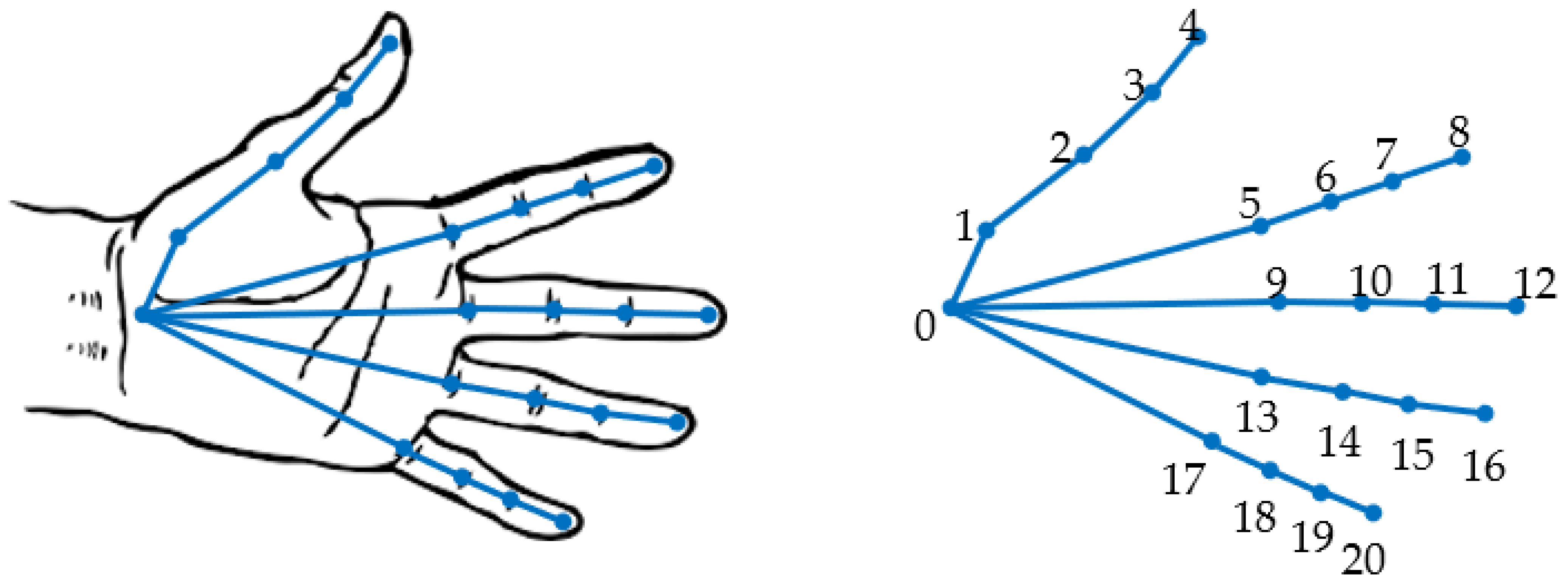
3.2.1. Hand Key-Point Detection by a Neural Network
3.2.2. Forearm Key-Point Detection
- -
- Initial evaluation of the approximate skeleton line of the forearm;
- -
- Final evaluation of the approximate skeleton line of the forearm;
- -
- Detection of forearm key points.
- -
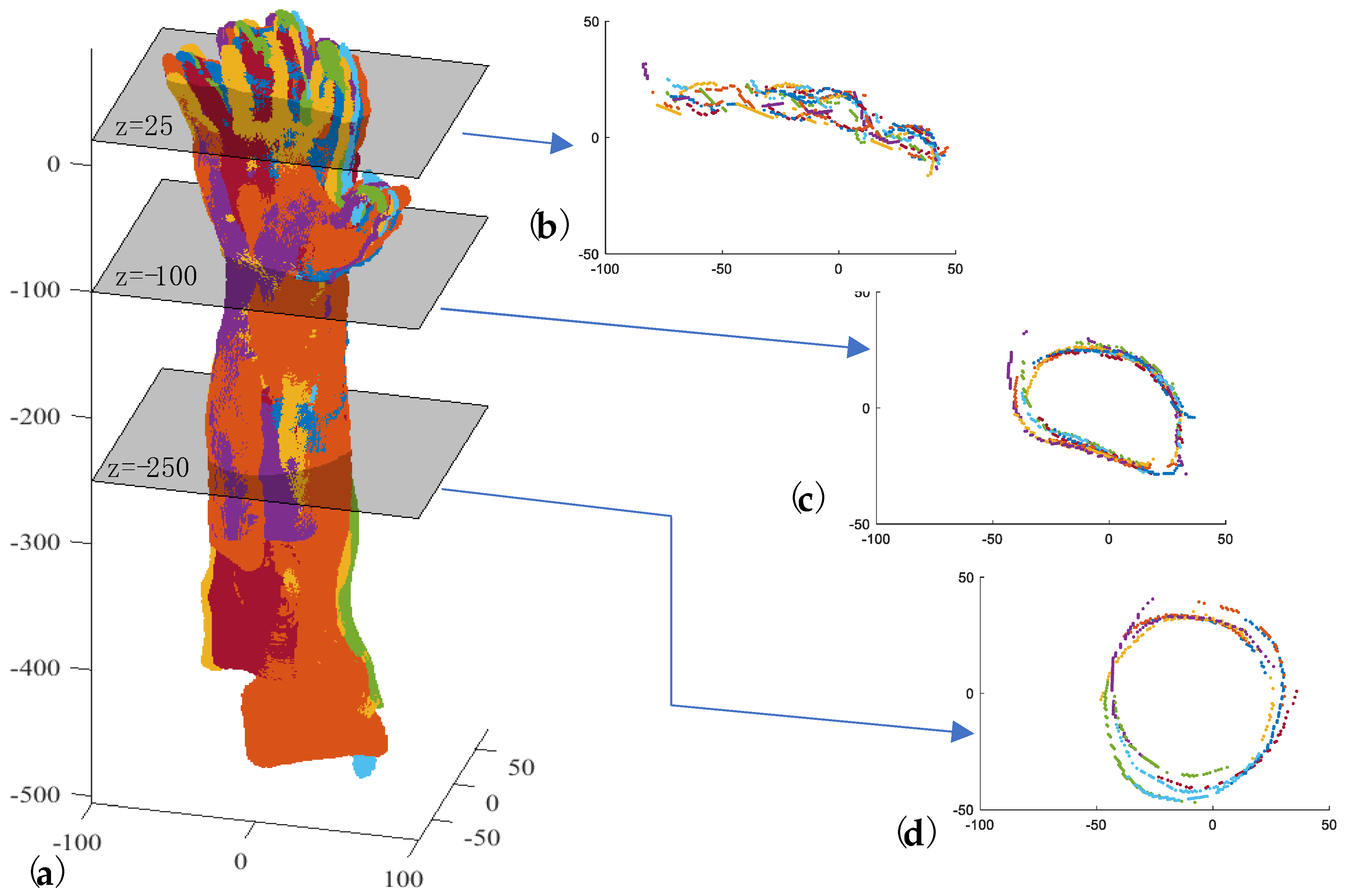
- Introducing a set of planes (Π) perpendicular to the z-axis with a defined pitch and intersecting Ti from a fixed height below the barycenter (Figure 6c);
- -
- Clustering the points (Γk) obtained for each plane intersection Πk (Figure 6c);
- -
- Approximating each Γk with an ellipse whose center is Ck (Figure 6d);
- -
- Approximating the centers Ck with a line by the RANSAC algorithm, thus obtaining ξf (Figure 6e).
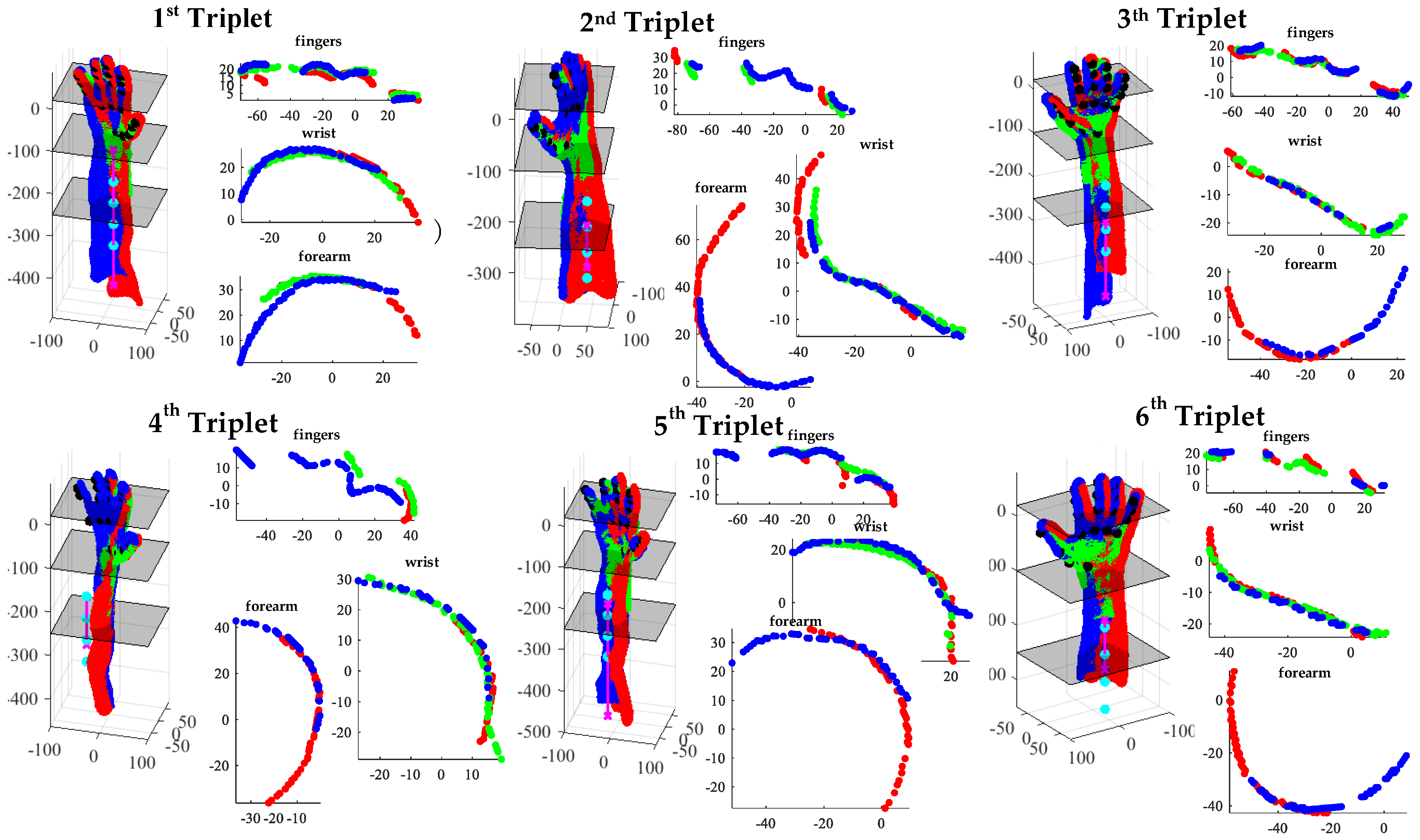
3.3. Coarse Registration of Point Cloud
3.4. Fine Registration of Point Clouds
| Algorithm 1. Developed algorithm for the fine global registration of np point clouds. |
| Require:}, Niter_ex |
Labeling of point clouds from 1 to np in a clockwise direction: |
| for h = 1 to Niter_ex do Select randomly the index of the fixed point cloud: Index_fixed_point_cloud = random(1,np) Reassign the labels to point clouds such that:
 for k = 2 to np do = fine_registration(℘fixed,) Update the ℘k alligment: Update the ℘fixed: end for end for |
4. Results and Discussion
4.1. Assessment of the Performance of the Proposed Methodology
| Algorithm 2. Algorithm for the fine global registration of np point clouds using the standard semi-automatic alignment pipeline. |
| Require:} |
Labeling of point clouds from 1 to np in a clockwise direction for h = 1 to np−1 do Fix and leave floating. Manual selection of at least three corresponding points (i.e., fingertips, elbow, wrist bones, natural skin marks) on common areas of and Rough alignment between the two adjacent point clouds using the 3-2-1 pairwise registration process. Fine registration between the two adjacent point clouds by ICP algorithm. end for Global registration by ICP algorithm |
4.2. Improvements to the State of the Art
- -
- The proposed algorithm for coarse registration is compared with the following:
- -
- The proposed algorithm for fine registration is compared with the following:
5. Conclusions
Author Contributions
Funding
Institutional Review Board Statement
Informed Consent Statement
Data Availability Statement
Conflicts of Interest
References
- Perry, J.C.; Brower, J.R.; Carne, R.H.R.; Bogert, M.A. 3D Scanning of the Forearm for Orthosis and HMI Applications. Front. Robot. Ai 2021, 8, 576783. [Google Scholar] [CrossRef]
- Leong, S.C.; Tang, Y.M.; Toh, F.M.; Fong, K.N.K. Examining the effectiveness of virtual, augmented, and mixed reality (VAMR) therapy for upper limb recovery and activities of daily living in stroke patients: A systematic review and meta-analysis. J. Neuroeng. Rehabil. 2022, 19, 93. [Google Scholar] [CrossRef]
- Urquhart, L.; Petrakis, K.; Hansen, J.P.; Wodehouse, A.; Mariani, M.E.; Lauer-Schmaltz, M.W.; Loudon, B. Prototyping Approaches for Rehabilitation Devices: From Product Embodiment to Data Management. Comput. Aided Des. Appl. 2023, 20, 145–157. [Google Scholar] [CrossRef]
- Bartol, K.; Bojanic, D.; Petkovic, T.; Pribanic, T. A Review of Body Measurement Using 3D Scanning. IEEE Access 2021, 9, 67281–67301. [Google Scholar] [CrossRef]
- Haleem, A.; Javaid, M. 3D scanning applications in medical field: A literature-based review. Clin. Epidemiol. Glob. 2019, 7, 199–210. [Google Scholar] [CrossRef]
- Grazioso, S.; Selvaggio, M.; Di Gironimo, G. Design and development of a novel body scanning system for healthcare applications. Int. J. Interact. Des. M 2018, 12, 611–620. [Google Scholar] [CrossRef]
- Zeraatkar, M.; Khalili, K. A Fast and Low-Cost Human Body 3D Scanner Using 100 Cameras. J. Imaging 2020, 6, 21. [Google Scholar] [CrossRef] [PubMed]
- Straub, J.; Kerlin, S. A Very Low-Cost 3D Scanning System for Whole-Body Imaging. In Smart Biomedical and Physiological Sensor Technology XII; SPIE: Bellingham, WA, USA, 2015; Volume 9487, pp. 122–131. [Google Scholar]
- Kersten, T.P.; Lindstaedt, M.; Starosta, D. Comparative Geometrical Accuracy Investigations of Hand-Held 3d Scanning Systems—AN Update. ISPRS—Int. Arch. Photogramm. Remote Sens. Spat. Inf. Sci. 2018, 422, 487–494. [Google Scholar] [CrossRef]
- Kalinowski, P.; Hindmarch, J.; Luhmann, T. Accuracy Investigations of Hand-Held Scanning Systems Using Different Dumbbell Artefacts. Int. Arch. Photogramm. Remote Sens. Spat. Inf. Sci. 2022, 43, 401–407. [Google Scholar] [CrossRef]
- Dessery, Y.; Pallari, J. Measurements agreement between low-cost and high-level handheld 3D scanners to scan the knee for designing a 3D printed knee brace. PLoS ONE 2018, 13, e0190585. [Google Scholar]
- Redaelli, D.F.; Barsanti, S.G.; Biffi, E.; Storm, F.A.; Colombo, G. Comparison of geometrical accuracy of active devices for 3D orthopaedic reconstructions. Int. J. Adv. Manuf. Tech. 2021, 114, 319–342. [Google Scholar] [CrossRef]
- Vitali, A.; Togni, G.; Regazzoni, D.; Rizzi, C.; Molinero, G. A virtual environment to evaluate the arm volume for lymphedema affected patients. Comput. Meth Prog. Bio 2021, 198, 105795. [Google Scholar] [CrossRef] [PubMed]
- Buonamici, F.; Carfagni, M.; Puggelli, L.; Servi, M.; Volpe, Y. A Fast and Reliable Optical 3D Scanning System for Human Arm. In Advances on Mechanics, Design Engineering and Manufacturing III; Roucoules, L., Paredes, M., Eynard, B., Morer Camo, P., Rizzi, C., Eds.; Springer International Publishing: Cham, Switzerland, 2021; pp. 268–273. [Google Scholar]
- Neri, P.; Barone, S.; Paoli, A.; Razionale, A.V.; Tamburrino, F. A Depth-Camera Based System for the Real-Time Scanning of Upper Limb Anatomy. In Proceedings of the International Conference on Design, Simulation, Manufacturing: The Innovation Exchange, Rome, Italy, 9–10 September 2021; Springer: Cham, Switzerland, 2022; pp. 245–255. [Google Scholar]
- Bernardini, F.; Rushmeier, H. The 3D model acquisition pipeline. Comput. Graph. Forum 2002, 21, 149–172. [Google Scholar] [CrossRef]
- Bonarrigo, F.; Signoroni, A. Global registration of large collections of range images with an improved Optimization-on-a-Manifold approach. Image Vis. Comput. 2014, 32, 437–451. [Google Scholar] [CrossRef][Green Version]
- Li, L.H.; Wang, R.W.; Zhang, X.P. A Tutorial Review on Point Cloud Registrations: Principle, Classification, Comparison, and Technology Challenges. Math. Probl. Eng. 2021, 2021, 9953910. [Google Scholar] [CrossRef]
- Pickup, D.; Sun, X.; Rosin, P.L.; Martin, R.R.; Cheng, Z.; Lian, Z.; Aono, M.; Ben Hamza, A.; Bronstein, A.; Bronstein, M.; et al. Shape Retrieval of Non-rigid 3D Human Models. Int. J. Comput. Vis. 2016, 120, 169–193. [Google Scholar] [CrossRef]
- Berretti, S.; Daoudi, M.; Turaga, P.; Basu, A. Representation, Analysis, and Recognition of 3D Humans: A Survey. Acm T Multim Comput. 2018, 14, 1–36. [Google Scholar] [CrossRef]
- Yan, Y.J.; An, J.Y.; Zhao, J.; Shen, F.R. Hybrid optimization with unconstrained variables on partial point cloud registration. Pattern Recogn. 2023, 136, 109267. [Google Scholar] [CrossRef]
- Han, X.-F.; Feng, Z.-A.; Sun, S.-J.; Xiao, G.-Q. 3D point cloud descriptors: State-of-the-art. Artif. Intell. Rev. 2023, 56, 12033–12083. [Google Scholar] [CrossRef]
- Cheng, L.; Chen, S.; Liu, X.Q.; Xu, H.; Wu, Y.; Li, M.C.; Chen, Y.M. Registration of Laser Scanning Point Clouds: A Review. Sensors 2018, 18, 1641. [Google Scholar] [CrossRef]
- Aiger, D.; Mitra, N.J.; Cohen-Or, D. 4-points congruent sets for robust pairwise surface registration. ACM Trans. Graph. 2008, 27, 1–10. [Google Scholar] [CrossRef]
- Mellado, N.; Aiger, D.; Mitra, N.J. SUPER 4PCS Fast Global Pointcloud Registration via Smart Indexing. Comput. Graph. Forum 2014, 33, 205–215. [Google Scholar] [CrossRef]
- Besl, P.J.; McKay, N.D. A method for registration of 3-D shapes. Ieee T Pattern Anal. 1992, 14, 239–256. [Google Scholar] [CrossRef]
- Chetverikov, D.; Svirko, D.; Stepanov, D.; Krsek, P. The Trimmed Iterative Closest Point Algorithm. In Proceedings of the 2002 International Conference on Pattern Recognition, Quebec City, QC, Canada, 11–15 August 2002; pp. 545–548. [Google Scholar]
- Wang, X.; Zhu, X.H.; Ying, S.H.; Shen, C.M. An Accelerated and Robust Partial Registration Algorithm for Point Clouds. IEEE Access 2020, 8, 156504–156518. [Google Scholar] [CrossRef]
- Du, S.Y.; Zhu, J.H.; Zheng, N.N.; Liu, Y.H.; Li, C. Robust iterative closest point algorithm for registration of point sets with outliers. Opt. Eng. 2011, 50, 087001. [Google Scholar] [CrossRef]
- Dong, J.M.; Peng, Y.X.; Ying, S.H.; Hu, Z.Y. LieTrICP: An improvement of trimmed iterative closest point algorithm. Neurocomputing 2014, 140, 67–76. [Google Scholar] [CrossRef]
- Dong, Z.; Liang, F.X.; Yang, B.S.; Xu, Y.S.; Zang, Y.F.; Li, J.P.; Wang, Y.; Dai, W.X.; Fan, H.C.; Hyyppa, J.; et al. Registration of large-scale terrestrial laser scanner point clouds: A review and benchmark. ISPRS J. Photogramm. 2020, 163, 327–342. [Google Scholar] [CrossRef]
- Wang, Y.J.; Yan, C.G.; Feng, Y.T.; Du, S.Y.; Dai, Q.H.; Gao, Y. STORM: Structure-Based Overlap Matching for Partial Point Cloud Registration. IEEE Trans. Pattern Anal. Mach. Intell. 2023, 45, 1135–1149. [Google Scholar] [CrossRef]
- Aoki, Y.; Goforth, H.; Srivatsan, R.A.; Lucey, S. PointNetLK: Robust & Efficient Point Cloud Registration using PointNet. In Proceedings of the 2019 IEEE/Cvf Conference on Computer Vision and Pattern Recognition (Cvpr 2019), Long Beach, CA, USA, 16–20 June 2019; pp. 7156–7165. [Google Scholar]
- Qi, C.R.; Su, H.; Mo, K.C.; Guibas, L.J. PointNet: Deep Learning on Point Sets for 3D Classification and Segmentation. In Proceedings of the 30th IEEE Conference on Computer Vision and Pattern Recognition (Cvpr 2017), Honolulu, HI, USA, 21–26 July 2017; pp. 77–85. [Google Scholar]
- Lucas, B.D.; Kanade, T. An Iterative Image Registration Technique with an Application to Stereo Vision. In Proceedings of the 7th International Joint Conference on Artificial Intelligence—Volume 2, Vancouver, BC, Canada, 24–28 August 1981; Morgan Kaufmann Publishers Inc.: San Francisco, CA, USA, 1981; pp. 674–679. [Google Scholar]
- Sarode, V.C.; Li, X.; Goforth, H.; Aoki, Y.; Rangaprasad, A.S.; Lucey, S.; Choset, H. PCRNet: Point Cloud Registration Network using PointNet Encoding. arXiv 2019, arXiv:1908.07906. [Google Scholar]
- Zhou, R.Q.; Li, X.X.; Jiang, W.S. SCANet: A Spatial and Channel Attention based Network for Partial-to-Partial Point Cloud Registration. Pattern Recogn. Lett. 2021, 151, 120–126. [Google Scholar] [CrossRef]
- Xu, H.; Liu, S.C.; Wang, G.F.; Liu, G.H.; Zeng, B. OMNet: Learning Overlapping Mask for Partial-to-Partial Point Cloud Registration. In Proceedings of the 2021 IEEE/Cvf International Conference on Computer Vision (Iccv 2021), Virtual, 11–17 October 2021; pp. 3112–3121. [Google Scholar]
- Zhang, W.H.; Zhang, Y.; Li, J.L. A Two-Stage Correspondence-Free Algorithm for Partially Overlapping Point Cloud Registration. Sensors 2022, 22, 4697. [Google Scholar] [CrossRef] [PubMed]
- Wang, Y.; Sun, Y.B.; Liu, Z.W.; Sarma, S.E.; Bronstein, M.M.; Solomon, J.M. Dynamic Graph CNN for Learning on Point Clouds. ACM Trans. Graph. 2019, 38, 1–12. [Google Scholar] [CrossRef]
- Zhang, K.G.; Hao, M.; Wang, J.; Chen, X.X.; Leng, Y.Q.; de Silva, C.W.; Fu, C.L. Linked Dynamic Graph CNN: Learning through Point Cloud by Linking Hierarchical Features. In Proceedings of the 2021 27th International Conference on Mechatronics and Machine Vision in Practice (M2VIP), Shanghai, China, 26–28 November 2021. [Google Scholar]
- Shen, Y.R.; Feng, C.; Yang, Y.; Tian, D. Mining Point Cloud Local Structures by Kernel Correlation and Graph Pooling. In Proceedings of the 2018 IEEE Conference on Computer Vision and Pattern Recognition, Salt Lake, UT, USA, 21–26 July 2018; pp. 4548–4557. [Google Scholar]
- Dominguez, M.; Dhamdhere, R.; Petkar, A.; Jain, S.; Sah, S.; Ptucha, R. General-Purpose Deep Point Cloud Feature Extractor. In Proceedings of the 2018 IEEE Winter Conference on Applications of Computer Vision (Wacv 2018), Lake Tahoe, NV, USA, 12–15 March 2018; pp. 1972–1981. [Google Scholar]
- Wang, L.; Huang, Y.C.; Hou, Y.L.; Zhang, S.M.; Shan, J. Graph Attention Convolution for Point Cloud Semantic Segmentation. In Proceedings of the 2019 IEEE/Cvf Conference on Computer Vision and Pattern Recognition (Cvpr 2019), Long Beach, CA, USA, 16–20 June 2019; pp. 10288–10297. [Google Scholar]
- Simonovsky, M.; Komodakis, N. Dynamic Edge-Conditioned Filters in Convolutional Neural Networks on Graphs. In Proceedings of the 30th IEEE Conference on Computer Vision and Pattern Recognition (Cvpr 2017), Honolulu, HI, USA, 21–26 July 2017; pp. 29–38. [Google Scholar]
- Xu, Q.G.; Sun, X.D.; Wu, C.Y.; Wang, P.Q.; Neumann, U. Grid-GCN for Fast and Scalable Point Cloud Learning. In Proceedings of the 2020 Proceedings of the IEEE/CVF Conference on Computer Vision and Pattern Recognition, Seattle, WA, USA, 14–19 June 2020; pp. 5660–5669. [Google Scholar]
- Shi, W.J.; Rajkumar, R. Point-GNN: Graph Neural Network for 3D Object Detection in a Point Cloud. In Proceedings of the 2020 IEEE/CVF Conference on Computer Vision and Pattern Recognition, Seattle, WA, USA, 14–19 June 2020; pp. 1708–1716. [Google Scholar]
- Carfagni, M.; Furferi, R.; Governi, L.; Santarelli, C.; Servi, M.; Uccheddu, F.; Volpe, Y. Metrological and Critical Characterization of the Intel D415 Stereo Depth Camera. Sensors 2019, 19, 489. [Google Scholar] [CrossRef] [PubMed]
- Chen, C.; Yang, B.S.; Song, S.; Tian, M.; Li, J.P.; Dai, W.X.; Fang, L.N. Calibrate Multiple Consumer RGB-D Cameras for Low-Cost and Efficient 3D Indoor Mapping. Remote Sens. 2018, 10, 328. [Google Scholar] [CrossRef]
- Neri, P.; Paoli, A.; Aruanno, B.; Barone, S.; Tamburrino, F.; Razionale, A.V. 3D scanning of Upper Limb anatomy by a depth-camera-based system. Int. J. Interact. Des. Manuf. (IJIDeM) 2023, 1–12. [Google Scholar] [CrossRef]
- Liu, Y.; Jiang, J.; Sun, J.H. Hand Pose Estimation from RGB Images Based on Deep Learning: A Survey. In Proceedings of the 2021 IEEE 7th International Conference on Virtual Reality (Icvr 2021), Foshan, China, 20–22 May 2021; pp. 82–89. [Google Scholar]
- Cao, Z.; Hidalgo, G.; Simon, T.; Wei, S.E.; Sheikh, Y. OpenPose: Realtime Multi-Person 2D Pose Estimation Using Part Affinity Fields. Ieee Trams. Pattern Anal. 2021, 43, 172–186. [Google Scholar] [CrossRef]
- MediaPipe Hand Landmarker. Available online: https://developers.google.com/mediapipe/solutions/vision/hand_landmarker (accessed on 9 September 2023).
- Horn, B.K.P.; Hilden, H.M.; Negahdaripour, S. Closed-form solution of absolute orientation using orthonormal matrices. J. Opt. Soc. Am. A 1988, 5, 1127–1135. [Google Scholar] [CrossRef]
- Kraft, D. A Software Package for Sequential Quadratic Programming; Tech. Rep. DFVLR-FB 88-28; DLR German Aerospace Center, Institute for Flight Mechanics: Koln, Germany; p. 1988.
- Tipping, M.E.; Bishop, C.M. Mixtures of Probabilistic Principal Component Analyzers. Neural Comput. 1999, 11, 443–482. [Google Scholar] [CrossRef]
- Rusu, R.B.; Blodow, N.; Beetz, M. Fast Point Feature Histograms (FPFH) for 3D Registration. In Proceedings of the 2009 IEEE International Conference on Robotics and Automation, Kobe, Japan, 12–17 May 2009; pp. 3212–3217. [Google Scholar]
- Chen, Y.; Medioni, G. Object modelling by registration of multiple range images. Image Vis. Comput. 1992, 10, 145–155. [Google Scholar] [CrossRef]
- Babin, P.; Giguère, P.; Pomerleau, F. Analysis of Robust Functions for Registration Algorithms. arXiv 2018, arXiv:cs.RO/1810.01474. [Google Scholar]


| Step | Parameter | Values |
|---|---|---|
| Hand key-point detection | Detection score threshold | 0.5 |
| Forearm key-point detection | HFKP: heights below the barycenter to define forearm key points | −200 mm:−50 mm:−350 mm |
| Coarse registration of point clouds | wH: Horn’s quaternion-based method weights [54] | 1 |
| Fine registration of point clouds | SLSQP Voxel grid | 0.75 mm |
| Toll: distance threshold value (Equations (3) and (5)) | 1.5 mm | |
| SLSQP Stopping criteria | ||
| Niter_ex (Algorithm 1) | 9 |
| Parameter | Hand | Arm | Total | |
|---|---|---|---|---|
| % points dist < 3 mm | mean | 0.884 | 0.859 | 0.870 |
| std | 0.088 | 0.073 | 0.014 | |
| % points dist < 6 mm | mean | 0.979 | 0.975 | 0.976 |
| std | 0.021 | 0.018 | 0.010 | |
| Dist, mm | mean | 1.429 | 1.634 | 1.522 |
| std | 0.572 | 0.363 | 0.026 | |
| Method | Parameters | Distances [mm] | |||||
|---|---|---|---|---|---|---|---|
| Total | Hand | Arm | |||||
| Mean | Std | Mean | Std | Mean | Std | ||
| Proposed method | See Table 1 | 2.440 | 0.742 | 2.871 | 1.011 | 2.175 | 0.725 |
| 4PCS [24] | d = 5, n = 200, t = 1000 | -- | -- | -- | -- | -- | -- |
| Super4PCS [25] | d = 5, n = 200, t = 1000 | -- | -- | -- | -- | -- | -- |
| PCA | n = 3 | 9.616 | 0.446 | 6.233 | 1.162 | 11.638 | 0.160 |
| FPFH | n = 3 | 5.137 | 1.012 | 4.154 | 0.911 | 5.722 | 1.031 |
| Method | Parameters | Distances [mm] | |||||
|---|---|---|---|---|---|---|---|
| Total | Hand | Arm | |||||
| Mean | Std | Mean | Std | Mean | Std | ||
| Proposed method | See Table 1 | 1.429 | 0.572 | 1.634 | 0.363 | 1.522 | 0.026 |
| ICP point-to-plane | d = 0.75, knn = 30 | 4.425 | 3.733 | 4.619 | 4.027 | 4.315 | 3.575 |
| ICP trimmed (Tukeyloss) point-to-plane | d = 0.75, knn = 30, sigma = 1.5 | 2.964 | 1.079 | 3.095 | 1.274 | 2.891 | 0.972 |
Disclaimer/Publisher’s Note: The statements, opinions and data contained in all publications are solely those of the individual author(s) and contributor(s) and not of MDPI and/or the editor(s). MDPI and/or the editor(s) disclaim responsibility for any injury to people or property resulting from any ideas, methods, instructions or products referred to in the content. |
© 2023 by the authors. Licensee MDPI, Basel, Switzerland. This article is an open access article distributed under the terms and conditions of the Creative Commons Attribution (CC BY) license (https://creativecommons.org/licenses/by/4.0/).
Share and Cite
Di Angelo, L.; Di Stefano, P.; Guardiani, E.; Neri, P.; Paoli, A.; Razionale, A.V. Automatic Multiview Alignment of RGB-D Range Maps of Upper Limb Anatomy. Sensors 2023, 23, 7841. https://doi.org/10.3390/s23187841
Di Angelo L, Di Stefano P, Guardiani E, Neri P, Paoli A, Razionale AV. Automatic Multiview Alignment of RGB-D Range Maps of Upper Limb Anatomy. Sensors. 2023; 23(18):7841. https://doi.org/10.3390/s23187841
Chicago/Turabian StyleDi Angelo, Luca, Paolo Di Stefano, Emanuele Guardiani, Paolo Neri, Alessandro Paoli, and Armando Viviano Razionale. 2023. "Automatic Multiview Alignment of RGB-D Range Maps of Upper Limb Anatomy" Sensors 23, no. 18: 7841. https://doi.org/10.3390/s23187841
APA StyleDi Angelo, L., Di Stefano, P., Guardiani, E., Neri, P., Paoli, A., & Razionale, A. V. (2023). Automatic Multiview Alignment of RGB-D Range Maps of Upper Limb Anatomy. Sensors, 23(18), 7841. https://doi.org/10.3390/s23187841