
Design and Implementation of a Highly Efficient Quasi-Cyclic Low-Density Parity-Check Transceiving System Using an Overlapping Decoder


Abstract
:1. Introduction
2. Architecture of CCSDS-like QC-LDPC Code for Overlap
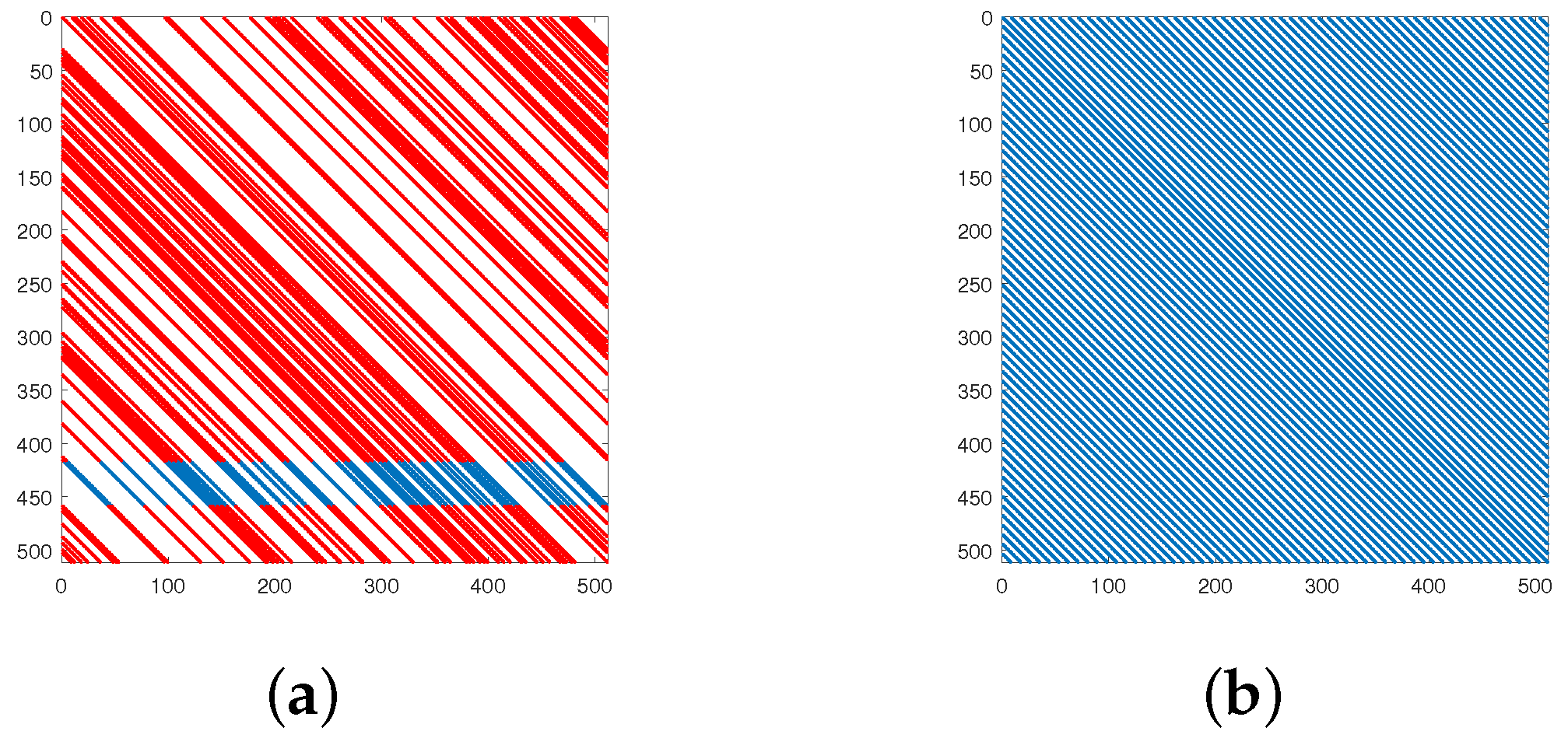
2.1. QC-LDPC Code
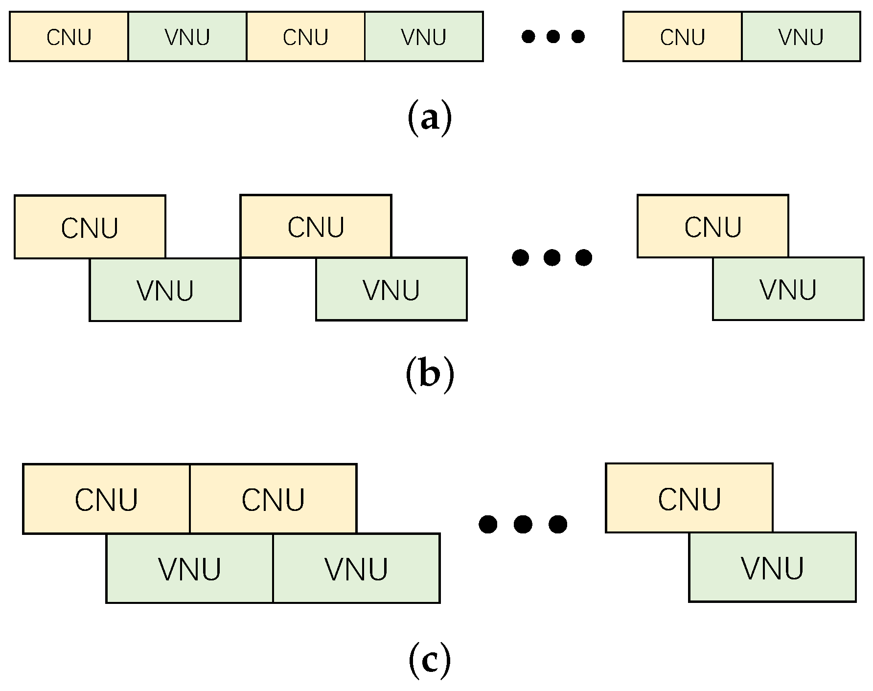
2.2. Overlapped Decoding Scheme
2.3. Architecture of the Proposed QC-LDPC Code
| Algorithm 1: Permutation Vector. |
Input: [] Output: |
3. Low-Complexity Decoding Algorithm
3.1. MSA
| Algorithm 2: Min-Sum Algorithm. |
| Input: rx and PCM Initialization:  Output: Decoded Data x |
3.2. Modified 2-Bit MSA
4. Computation Unit Design for the Decoder
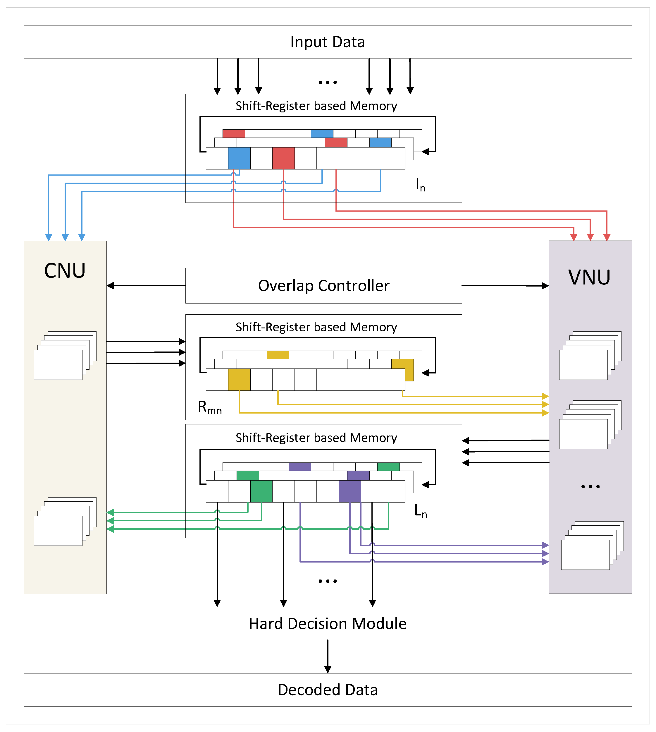
4.1. System Architecture
4.2. CNU
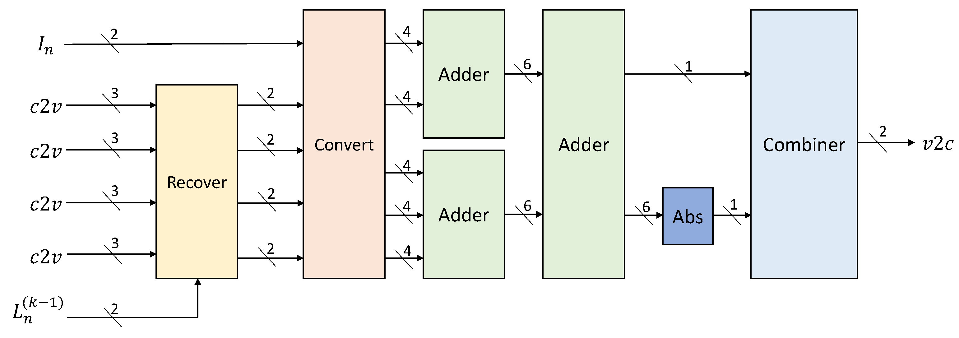
4.3. VNU
5. Overlapped Decoding Scheme for the Proposed QC-LDPC Code
5.1. Shift-Register-Based Memory Strategy
5.2. Overlap Controller
6. Results and Discussion
6.1. Simulation Results
6.2. Experimental Results
7. Conclusions
Author Contributions
Funding
Conflicts of Interest
References
- Gallager, R. Low-density parity-check codes. IRE Trans. Inf. Theory 1962, 8, 21–28. [Google Scholar] [CrossRef]
- Zhang, L. Development and Prospect of Chinese Lunar Relay Communication Satellite. Space Sci. Technol. 2021, 2021, 3471608. [Google Scholar] [CrossRef]
- Meng, Q.; Huang, M.; Xu, Y.; Liu, N.; Xiang, X. Decentralized Distributed Deep Learning with Low-Bandwidth Consumption for Smart Constellations. Space Sci. Technol. 2021, 2021, 9879246. [Google Scholar] [CrossRef]
- Chung, S.Y.; Forney, G.D.; Richardson, T.J.; Urbanke, R. On the design of low-density parity-check codes within 0.0045 dB of the Shannon limit. IEEE Commun. Lett. 2001, 5, 58–60. [Google Scholar] [CrossRef]
- Shi, M.; Yang, K.; Niyato, D.; Yuan, H.; Zhou, H.; Xu, Z. The Meta Distribution of SINR in UAV-Assisted Cellular Networks. IEEE Trans. Commun. 2023, 71, 1193–1206. [Google Scholar] [CrossRef]
- Barry, J.R. Low-density parity-check codes. Ga. Inst. Technol. 2001, 5, 21–28. [Google Scholar]
- Chen, X.; Kang, J.; Lin, S.; Akella, V. Memory system optimization for FPGA-based implementation of quasi-cyclic LDPC codes decoders. IEEE Trans. Circuits Syst. I Regul. Pap. 2010, 58, 98–111. [Google Scholar] [CrossRef]
- Chandrasetty, V.A.; Aziz, S.M. Resource efficient LDPC decoders for multimedia communication. Integration 2015, 48, 213–220. [Google Scholar] [CrossRef]
- Andreadou, N.; Pavlidou, F.N.; Papaharalabos, S.; Mathiopoulos, P.T. Quasi-Cyclic Low-Density Parity-Check (QC-LDPC) codes for deep space and high data rate applications. In Proceedings of the 2009 International Workshop on Satellite and Space Communications, Siena, Italy, 9–11 September 2009; pp. 225–229. [Google Scholar]
- Wang, Y.; Yedidia, J.; Draper, S. Construction of high-girth QC-LDPC codes. In Proceedings of the 2008 5th International Symposium on Turbo Codes and Related Topics, Lausanne, Switzerland, 1–5 September 2008; pp. 180–185. [Google Scholar]
- CCSDS-131.1-O-2; Low Density Parity Check Codes for Use in Near-Earth and Deep Space Applocations. Consultative Committee for Space Data Systems: Washington, DC, USA, 2007.
- Lou, J.; Jiao, Y.; Yang, R.; Huang, Y.; Xu, X.; Zhang, L.; Ma, Z.; Yu, Y.; Peng, W.; Yuan, Y.; et al. Calibration-free, high-precision, and robust terahertz ultrafast metasurfaces for monitoring gastric cancers. Proc. Natl. Acad. Sci. USA 2022, 119, e2209218119. [Google Scholar] [CrossRef]
- Lou, J.; Xu, X.; Huang, Y.; Yu, Y.; Wang, J.; Fang, G.; Liang, J.; Fan, C.; Chang, C. Optically controlled ultrafast terahertz metadevices with ultralow pump threshold. Small 2021, 17, 2104275. [Google Scholar] [CrossRef]
- Xu, X.; Lou, J.; Wu, S.; Yu, Y.; Liang, J.; Huang, Y.; Fang, G.; Chang, C. SnSe 2-functionalized ultrafast terahertz switch with ultralow pump threshold. J. Mater. Chem. C 2022, 10, 5805–5812. [Google Scholar] [CrossRef]
- Ye, N.; Cao, X.; Ding, X.; Li, J.; Zhao, D.; Ouyang, Q. Multi-Connection to the Sky: Energy-Efficient Beamforming for Multi-Satellite Uplink Transmission With Lens Antenna Array. IEEE Trans. Green Commun. Netw. 2023. [Google Scholar] [CrossRef]
- Pourjabar, S.; Choi, G.S. A High-Throughput Multi-Mode LDPC Decoder for 5G NR. arXiv 2021, arXiv:2102.13228. [Google Scholar]
- Lu, Q.; Sham, C.W.; Lau, F. Rapid prototyping of multi-mode QC-LDPC decoder for 802.11n/ac standard. In Proceedings of the Asia & South Pacific Design Automation Conference, Macao, China, 25–28 January 2016. [Google Scholar]
- Yang, S.S.; Liu, J.Q.; Lu, Z.G.; Bai, Z.L.; Wang, X.Y.; Li, Y.M. An FPGA-Based LDPC Decoder With Ultra-Long Codes for Continuous-Variable Quantum Key Distribution. IEEE Access 2021, 9, 47687–47697. [Google Scholar] [CrossRef]
- Yeo, E.; Pakzad, P.; Nikolic, B.; Anantharam, V. VLSI architectures for iterative decoders in magnetic recording channels. IEEE Trans. Magn. 2001, 37, 748–755. [Google Scholar]
- Chen, Y.; Parhi, K.K. Overlapped message passing for quasi-cyclic low-density parity check codes. IEEE Trans. Circuits Syst. I Regul. Pap. 2004, 51, 1106–1113. [Google Scholar] [CrossRef]
- Wang, Z.; Cui, Z. Low-Complexity High-Speed Decoder Design for Quasi-Cyclic LDPC Codes. IEEE Trans. Very Large Scale Integr. Syst. 2007, 15, 104–114. [Google Scholar] [CrossRef]
- Cui, Z.; Wang, Z. Improved low-complexity low-density parity-check decoding. IET Commun. 2008, 2, 1061–1068. [Google Scholar] [CrossRef]
- Fossorier, M.P. Quasicyclic low-density parity-check codes from circulant permutation matrices. IEEE Trans. Inf. Theory 2004, 50, 1788–1793. [Google Scholar] [CrossRef]
- Nguyen, T.; Tan, T.N.; Lee, H. Low-Complexity High-Throughput QC-LDPC Decoder for 5G New Radio Wireless Communication. Electronics 2021, 10, 516. [Google Scholar] [CrossRef]
- Kim, S.M.; Parhi, K.K. Overlapped decoding for a class of quasi-cyclic LDPC codes. In Proceedings of the IEEE Workshop on Signal Processing Systems, Austin, TX, USA, 13–15 October 2004. [Google Scholar]
- Echard, R.; Chang, S.C. Design considerations leading to the development of good π-rotation LDPC codes. IEEE Commun. Lett. 2005, 5, 447–449. [Google Scholar] [CrossRef]
- MacKay, D.J.; Neal, R.M. Good codes based on very sparse matrices. In Proceedings of the IMA International Conference on Cryptography and Coding, Cirencester, UK, 18–20 December 1995; Springer: Berlin/Heidelberg, Germany, 1995; pp. 100–111. [Google Scholar]
- Envelope, D.; Selvakumari, R.S. Performance analysis of Min-Sum based LDPC decoder architecture for 5G new radio standards. Mater. Today Proc. 2022, 62, 4965–4972. [Google Scholar]
- Hatami, H.; Mitchell, D.; Costello, D.J.; Fuja, T.E. A Threshold-Based Min-Sum Algorithm to Lower the Error Floors of Quantized LDPC Decoders. IEEE Trans. Commun. 2020, 68, 2005–2015. [Google Scholar] [CrossRef]
- Fossorier, M.P.C.; Mihaljevic, M.; Imai, H. Reduced complexity iterative decoding of low-density parity check codes based on belief propagation. IEEE Trans. Commun. 2002, 47, 673–680. [Google Scholar] [CrossRef]
- Zarubica, R.; Hinton, R.; Wilson, S.G.; Hall, E.K. Efficient quantization schemes for LDPC decoders. In Proceedings of the Military Communications Conference, MILCOM 2008, San Diego, CA, USA, 16–19 November 2008. [Google Scholar]
- Chandrasetty, V.A.; Aziz, S.M. FPGA implementation of high performance LDPC decoder using modified 2-bit min-sum algorithm. In Proceedings of the 2010 Second International Conference on Computer Research and Development, Washington, DC, USA, 7–10 May 2010; pp. 881–885. [Google Scholar]
- Chandrasetty, V.A.; Aziz, S.M. An area efficient LDPC decoder using a reduced complexity min-sum algorithm. Integration 2012, 45, 141–148. [Google Scholar] [CrossRef]
- Cushon, K.; Hemati, S.; Leroux, C.; Mannor, S.; Gross, W.J. High-Throughput Energy-Efficient LDPC Decoders Using Differential Binary Message Passing. IEEE Trans. Signal Process. Publ. IEEE Signal Process. Soc. 2014, 62, 619–631. [Google Scholar] [CrossRef]
- Dai, Y.; Yan, Z.; Chen, N. Optimal overlapped message passing decoding of quasi-cyclic LDPC codes. IEEE Trans. Very Large Scale Integr. (VLSI) Syst. 2008, 16, 565–578. [Google Scholar]
- Petrović, V.L.; Marković, M.M.; El Mezeni, D.M.; Saranovac, L.V.; Radošević, A. Flexible high throughput QC-LDPC decoder with perfect pipeline conflicts resolution and efficient hardware utilization. IEEE Trans. Circuits Syst. I Regul. Pap. 2020, 67, 5454–5467. [Google Scholar] [CrossRef]
- Ghanaatian, R.; Balatsoukas-Stimming, A.; Müller, T.C.; Meidlinger, M.; Matz, G.; Teman, A.; Burg, A. A 588-Gb/s LDPC decoder based on finite-alphabet message passing. IEEE Trans. Very Large Scale Integr. (VLSI) Syst. 2017, 26, 329–340. [Google Scholar] [CrossRef]
- Khittiwitchayakul, S.; Phakphisut, W.; Supnithi, P. Reliability Ratio-Based Serial Algorithm of LDPC Decoder for Turbo Equalization Schemes. IEEE Trans. Magn. 2021, 58, 3100205. [Google Scholar] [CrossRef]
- Shi, H.; Zhong, M.; Luo, Z.; Li, C. Low Complexity Neural Network-Aided NMS LDPC Decoder. In Proceedings of the 2021 Computing, Communications and IoT Applications (ComComAp), Shenzhen, China, 26–28 November 2021; pp. 227–231. [Google Scholar]
- Zhang, K.; Huang, X.; Wang, Z. High-throughput layered decoder implementation for quasi-cyclic LDPC codes. IEEE J. Sel. Areas Commun. 2009, 27, 985–994. [Google Scholar] [CrossRef]
- Xie, T.; Li, B.; Yang, M.; Yan, Z. Memory compact high-speed QC-LDPC decoder. In Proceedings of the 2017 IEEE International Conference on Signal Processing, Communications and Computing (ICSPCC), Xiamen, China, 22–25 October 2017; pp. 1–5. [Google Scholar]
- Kang, J.; Wang, B.; Zhang, Y.; An, J. Enhanced Partially Parallel LDPC Decoder for Near Earth Applications. In Proceedings of the 2021 IEEE 11th International Conference on Electronics Information and Emergency Communication (ICEIEC), Beijing, China, 18–20 June 2021; pp. 12–16. [Google Scholar]


| Computation Unit | LUT | Register | RAM | DSP |
|---|---|---|---|---|
| CNU | 0 | 0 | ||
| VNU | 0 | 0 | ||
| Permutation Net | 51,944 | 114,004 | 0 | 0 |
| Total | 73,718 | 142,504 | 0 | 0 |
| Available | 1,182,240 | 236,4480 | 2160 | 6840 |
| Proposed Decoder | [36] | [16] | [41] | [42] | |
|---|---|---|---|---|---|
| Standard | Proposed LDPC | 5G NR | 5G NR | CCSDS | CCSDS |
| Code Rate | 7/8 | 22/27 | 1/3 | 7/8 | 7/8 |
| Code Length | 8176 | 10368 | 6528 | 8176 | 8176 |
| Max. Iter. | 8 | 5 | 10 | 10 | 10 |
| Algorithm | Modified 2-bit MSA | Hybrid Schedule | OMS | F-NMS | F-AMSA |
| LLRs Quant. | 2 | 8 | 5 | 7 | 6 |
| Throughput (Gbps) | 7.76 | 31.7 | 2.168 | 2 | 1.02 |
| Frequency (MHz) | 156.25 | 261 | 82 | 250 | 250 |
| LUT | 73,718 | 100,929 | 225,191 | 56,778 | 46,294 |
| FFs | 142,504 | 85,431 | - | 86,942 | 39,103 |
| BRAM(KB) | 0 | 4896 | 3456 | 573 | 253 |
| Mbps/kLUT | 106.3 | 314.2 | 9.6 | 35.7 | 22.2 |
| Mbps/kFF | 54.6 | 371.3 | - | 23 | 26.2 |
| Mbps/36 kb BRAM | - | 232.4 | 22.6 | 125 | 145 |
Disclaimer/Publisher’s Note: The statements, opinions and data contained in all publications are solely those of the individual author(s) and contributor(s) and not of MDPI and/or the editor(s). MDPI and/or the editor(s) disclaim responsibility for any injury to people or property resulting from any ideas, methods, instructions or products referred to in the content. |
© 2023 by the authors. Licensee MDPI, Basel, Switzerland. This article is an open access article distributed under the terms and conditions of the Creative Commons Attribution (CC BY) license (https://creativecommons.org/licenses/by/4.0/).
Share and Cite
Sun, Y.; Zhao, L.; Li, J.; Zhang, Z.; Yang, X.; Bu, X. Design and Implementation of a Highly Efficient Quasi-Cyclic Low-Density Parity-Check Transceiving System Using an Overlapping Decoder. Sensors 2023, 23, 7828. https://doi.org/10.3390/s23187828
Sun Y, Zhao L, Li J, Zhang Z, Yang X, Bu X. Design and Implementation of a Highly Efficient Quasi-Cyclic Low-Density Parity-Check Transceiving System Using an Overlapping Decoder. Sensors. 2023; 23(18):7828. https://doi.org/10.3390/s23187828
Chicago/Turabian StyleSun, Yuxuan, Liangbin Zhao, Jianguo Li, Ziyi Zhang, Xiao Yang, and Xiangyuan Bu. 2023. "Design and Implementation of a Highly Efficient Quasi-Cyclic Low-Density Parity-Check Transceiving System Using an Overlapping Decoder" Sensors 23, no. 18: 7828. https://doi.org/10.3390/s23187828
APA StyleSun, Y., Zhao, L., Li, J., Zhang, Z., Yang, X., & Bu, X. (2023). Design and Implementation of a Highly Efficient Quasi-Cyclic Low-Density Parity-Check Transceiving System Using an Overlapping Decoder. Sensors, 23(18), 7828. https://doi.org/10.3390/s23187828