

Can Wearable Sensors Provide Accurate and Reliable 3D Tibiofemoral Angle Estimates during Dynamic Actions?
Abstract
1. Introduction
2. Materials and Methods
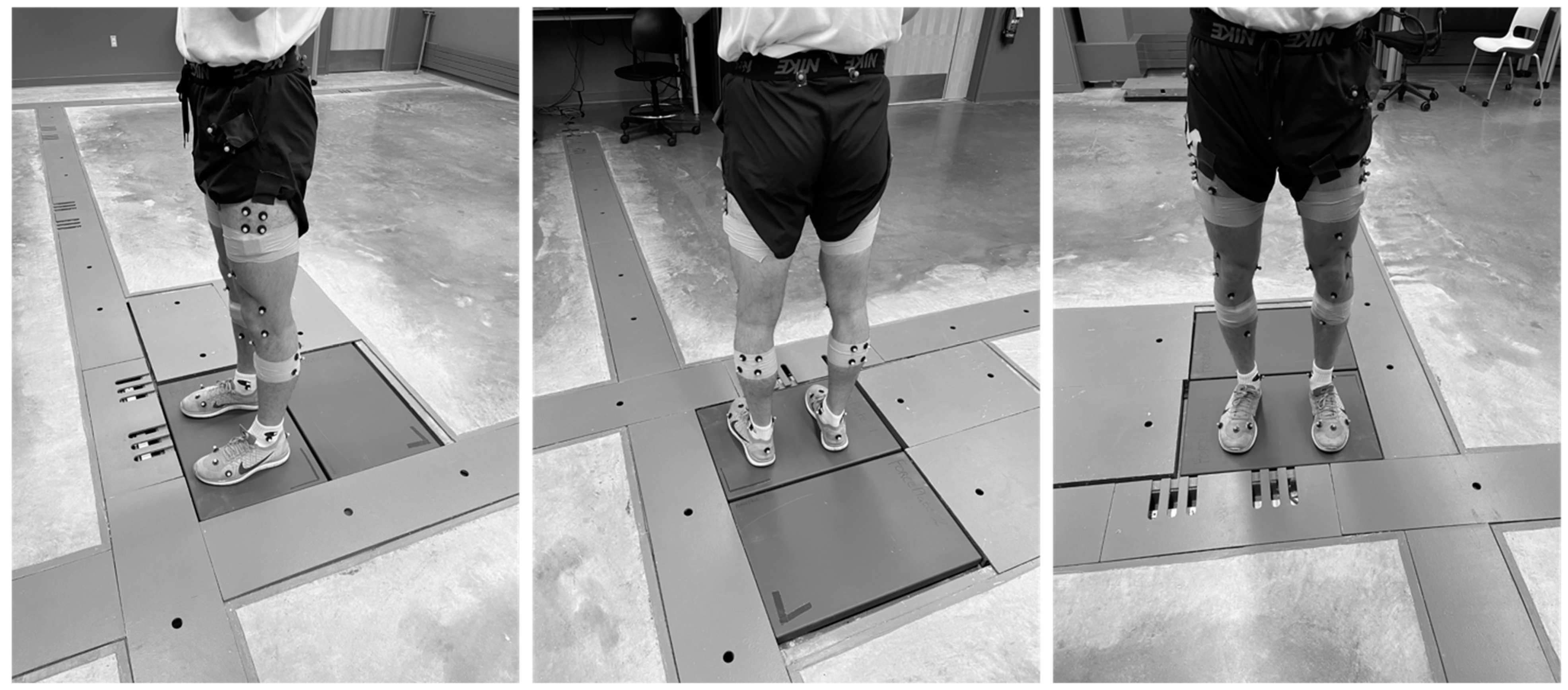
2.1. Subjects, Instrumentation, and Testing Procedures
2.2. Data Processing
2.3. Parameters Used in the TQC Method
2.4. Statistical Analysis
3. Results
3.1. Training Set
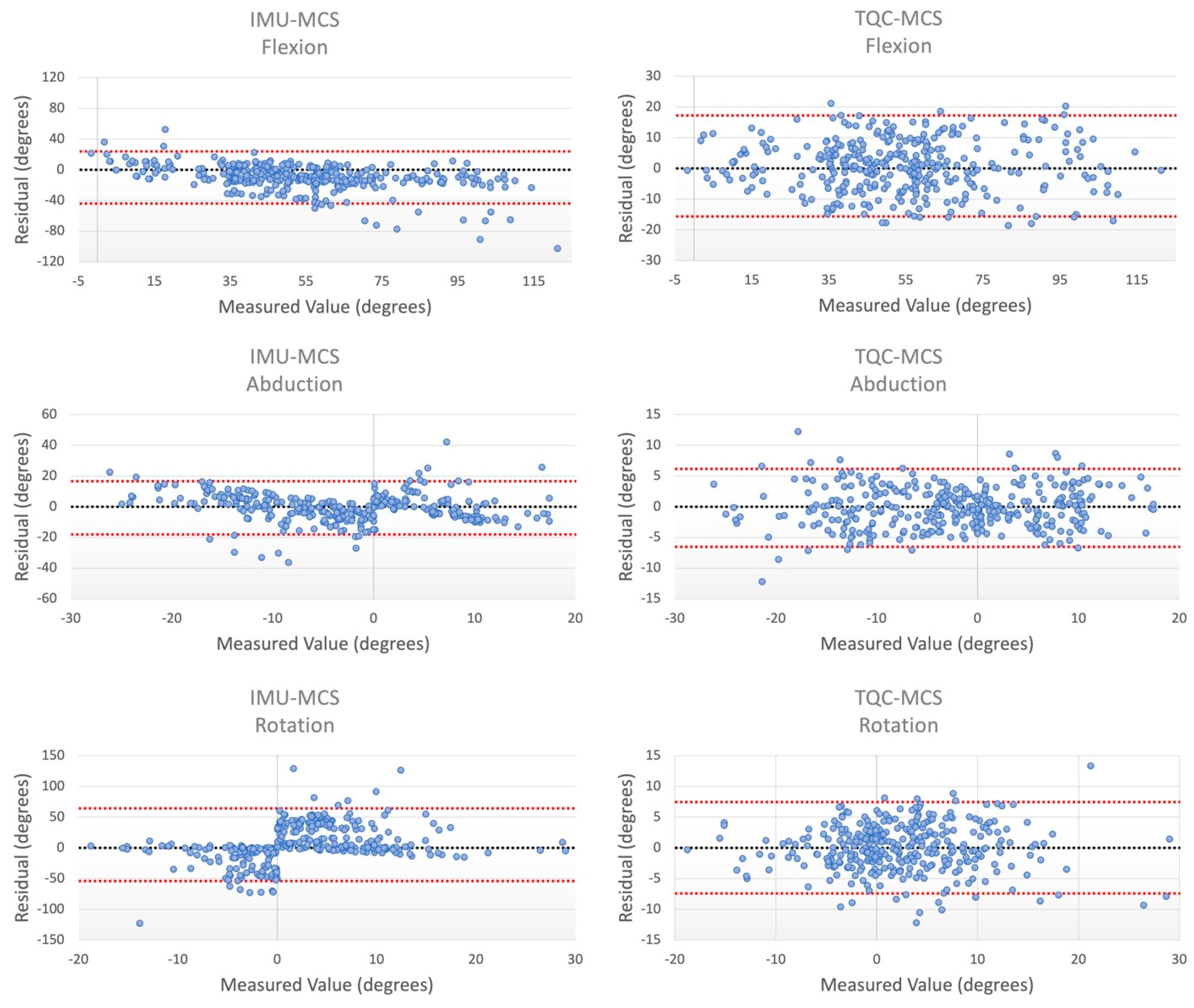
3.2. Testing Set
4. Discussion
Limitations
5. Conclusions
Author Contributions
Funding
Institutional Review Board Statement
Informed Consent Statement
Data Availability Statement
Acknowledgments
Conflicts of Interest
References
- Gornitzky, A.L.; Lott, A.; Yellin, J.L.; Fabricant, P.D.; Ganley, T.J. Sport-Specific Yearly Risk and Incidence of Anterior Cruciate Ligament Tears in High School Athletes: A Systematic Review and Meta-Analysis. Pediatrics 2016, 137, 561. [Google Scholar] [CrossRef]
- Hootman, J.M.; Dick, R.; Agel, J. Epidemiology of Collegiate Injuries for 15 Sports: Summary and Recommendations for Injury Prevention Initiatives. J. Athl. Train. 2007, 42, 311–319. [Google Scholar]
- Toth, A.P.; Cordasco, F.A. Anterior cruciate ligament injuries in the female athlete. J. Gend.-Specif. Med. JGSM Off. J. Partnersh. Women’s Health Columbia 2001, 4, 25–34. [Google Scholar]
- Saltzman, B.M.; Cvetanovich, G.L.; Nwachukwu, B.U.; Mall, N.A.; Bush-Joseph, C.A.; Bach, B.R., Jr. Economic Analyses in Anterior Cruciate Ligament Reconstruction: A Qualitative and Systematic Review. Am. J. Sports Med. 2015, 44, 1329–2133. [Google Scholar] [CrossRef] [PubMed]
- Ladenhauf, H.N.; Graziano, J.; Marx, R.G. Anterior cruciate ligament prevention strategies: Are they effective in young athletes—Current concepts and review of literature. Curr. Opin Pediatr. 2013, 25, 64–71. [Google Scholar] [CrossRef] [PubMed]
- Von Porat, A.; Roos, E.M.; Roos, H. High prevalence of osteoarthritis 14 years after an anterior cruciate ligament tear in male soccer players: A study of radiographic and patient relevant outcomes. Ann. Rheum. Dis. 2004, 63, 269–273. [Google Scholar] [CrossRef] [PubMed]
- Faunø, P.; Jakobsen, B.W. Mechanism of Anterior Cruciate Ligament Injuries in Soccer. Int. J. Sports Med. 2005, 27, 75–79. [Google Scholar] [CrossRef]
- Hewett, T.E.; Myer, G.D.; Ford, K.R.; Heidt, R.S., Jr.; Colosimo, A.J.; McLean, S.G.; Van Den Bogert, A.J.; Paterno, M.V.; Succop, P. Biomechanical Measures of Neuromuscular Control and Valgus Loading of the Knee Predict Anterior Cruciate Ligament Injury Risk in Female Athletes: A Prospective Study. Am. J. Sports Med. 2005, 33, 492–501. [Google Scholar] [CrossRef]
- Schmitz, R.J.; Kulas, A.S.; Perrin, D.H.; Riemann, B.L.; Shultz, S.J. Sex differences in lower extremity biomechanics during single leg landings. Clin. Biomech. 2007, 22, 681–688. [Google Scholar] [CrossRef]
- Yu, B.; Lin, C.-F.; Garrett, W.E. Lower extremity biomechanics during the landing of a stop-jump task. Clin. Biomech. 2006, 21, 297–305. [Google Scholar] [CrossRef]
- Zeller, B.L.; McCrory, J.L.; Ben Kibler, W.; Uhl, T.L. Differences in Kinematics and Electromyographic Activity between Men and Women during the Single-Legged Squat. Am. J. Sports Med. 2003, 31, 449–456. [Google Scholar] [CrossRef]
- Miranda, D.L.; Fadale, P.D.; Hulstyn, M.J.; Shalvoy, R.M.; Machan, J.T.; Fleming, B.C. Knee biomechanics during a jump-cut maneuver: Effects of sex and ACL surgery. Med. Sci. Sports Exerc. 2013, 45, 942–951. [Google Scholar] [CrossRef] [PubMed]
- Griffin, L.Y.; Agel, J.; Albohm, M.J.; Arendt, E.A.; Dick, R.W.; Garrett, W.E.; Garrick, J.G.; Hewett, T.E.; Huston, L.; Ireland, M.L.; et al. Noncontact Anterior Cruciate Ligament Injuries: Risk Factors and Prevention Strategies. J. Am. Acad. Orthop. Surg. 2000, 8, 141–150. [Google Scholar] [CrossRef] [PubMed]
- Wild, C.Y.; Steele, J.R.; Munro, B.J. Why do girls sustain more anterior cruciate ligament injuries than boys?: A review of the changes in estrogen and musculoskeletal structure and function during puberty. Sports Med. 2012, 42, 733–749. [Google Scholar] [CrossRef] [PubMed]
- Yin, L.; Sun, D.; Mei, Q.; Gu, Y.; Baker, J.; Feng, N. The Kinematics and Kinetics Analysis of the Lower Extremity in the Landing Phase of a Stop-jump Task. Open Biomed. Eng. J. 2015, 9, 103–107. [Google Scholar] [CrossRef]
- Yu, B.; Garrett, W.E. Mechanisms of non-contact ACL injuries. Br. J. Sports Med. 2007, 41 (Supp. S1), i47–i51. [Google Scholar] [CrossRef]
- Ananthanarayan, S.; Sheh, M.; Chien, A.; Profita, H.; Siek, K.A. Designing wearable interfaces for knee rehabilitation. In Proceedings of the 8th International Conference on Pervasive Computing Technologies for Healthcare, Oldenburg, Germany, 20 May 2014. [Google Scholar]
- Arif, M.; Kattan, A. Physical Activities Monitoring Using Wearable Acceleration Sensors Attached to the Body. PLoS ONE 2015, 10, e0130851. [Google Scholar] [CrossRef]
- Bakhshi, S.; Mahoor, M.H.; Davidson, B.S. Development of a body joint angle measurement system using IMU sensors. In Proceedings of the 33rd Annual International Conference of the IEEE EMBS, Boston, MA, USA, 30 August–3 September 2011. [Google Scholar]
- Bamberg, S.J.M.; Benbasat, A.Y.; Scarborough, D.M.; Krebs, D.E.; Paradiso, J.A. Gait Analysis Using a Shoe-Integrated Wireless Sensor System. IEEE Trans. Inf. Technol. Biomed. 2008, 12, 413–423. [Google Scholar] [CrossRef] [PubMed]
- Barrios, J.A.; Crossley, K.M.; Davis, I.S. Gait retraining to reduce the knee adduction moment through real-time visual feedback of dynamic knee alignment. J. Biomech. 2010, 43, 2208–2213. [Google Scholar] [CrossRef] [PubMed]
- Chen, K.-H.; Chen, P.-C.; Liu, K.-C.; Chan, C.-T. Wearable Sensor-Based Rehabilitation Exercise Assessment for Knee Osteoarthritis. Sensors 2015, 15, 4193–4211. [Google Scholar] [CrossRef] [PubMed]
- Anderson, C.J.; Ziegler, C.G.; Wijdicks, C.A.; Engebretsen, L.; LaPrade, R.F. Arthroscopically Pertinent Anatomy of the Anterolateral and Posteromedial Bundles of the Posterior Cruciate Ligament. J. Bone Jt. Surg. 2012, 94, 1936–1945. [Google Scholar] [CrossRef]
- Cutti, A.G.; Ferrari, A.; Garofalo, P.; Raggi, M.; Cappello, A.; Ferrari, A. ‘Outwalk’: A protocol for clinical gait analysis based on inertial and magnetic sensors. Med. Biol. Eng. Comput. 2009, 48, 17–25. [Google Scholar] [CrossRef]
- Favre, J.; Crevoisier, X.; Jolles, B.; Aminian, K. Evaluation of a mixed approach combining stationary and wearable systems to monitor gait over long distance. J. Biomech. 2010, 43, 2196–2202. [Google Scholar] [CrossRef] [PubMed]
- Ferrari, A.; Cutti, A.G.; Garofalo, P.; Raggi, M.; Heijboer, M.; Cappello, A.; Davalli, A. First in vivo assessment of “Outwalk”: A novel protocol for clinical gait analysis based on inertial and magnetic sensors. Med. Biol. Eng. Comput. 2009, 48, 1–15. [Google Scholar] [CrossRef] [PubMed]
- Lin, J.F.S.; Kulić, D. Human pose recovery using wireless inertial measurement units. Physiol. Meas. 2012, 33, 2099–2115. [Google Scholar] [CrossRef] [PubMed]
- Picerno, P.; Cereatti, A.; Cappozzo, A. Joint kinematics estimate using wearable inertial and magnetic sensing modules. Gait Posture 2008, 28, 588–595. [Google Scholar] [CrossRef]
- Wojtys, E.M.; Beaulieu, M.L.; Ashton-Miller, J.A. New perspectives on ACL injury: On the role of repetitive sub-maximal knee loading in causing ACL fatigue failure. J. Orthop. Res. 2016, 34, 2059–2068. [Google Scholar] [CrossRef] [PubMed]
- Olsen, O.E.; Myklebust, G.; Engebretsen, L.; Bahr, R. Injury mechanisms for anterior cruciate ligament injuries in team handball: A systematic video analysis. Am. J. Sports Med. 2004, 32, 1002–1012. [Google Scholar] [CrossRef]
- Renstrom, P.; Ljungqvist, A.; Arendt, E.A.; Beynnon, B.D.; Fukubayashi, T.; Garrett, W.E.; Georgoulis, T.; Hewett, T.E.; Johnson, R.P.; Krosshaug, T.; et al. Non-contact ACL injuries in female athletes: An International Olympic Committee current concepts statement. Br. J. Sports Med. 2008, 42, 394–412. [Google Scholar] [CrossRef]
- Ajdaroski, M.; Tadakala, R.; Nichols, L.; Esquivel, A. Validation of a Device to Measure Knee Joint Angles for a Dynamic Movement. Sensors 2020, 20, 1747. [Google Scholar] [CrossRef]
- Barrett, J.M.; Viggiani, D.; Park, J.; Callaghan, J.P. Expressing angles relative to reference postures: A mathematical comparison of four approaches. J. Biomech. 2020, 104, 109733. [Google Scholar] [CrossRef]
- Watanabe, T.; Saito, H. Tests of wireless wearable sensor system in joint angle measurement of lower limbs. Annu. Int. Conf. IEEE Eng. Med. Biol. Soc. 2011, 2011, 5469–5472. [Google Scholar] [CrossRef]
- Tong, K.; Granat, M.H. A practical gait analysis system using gyroscopes. Med. Eng. Phys. 1999, 21, 87–94. [Google Scholar] [CrossRef]
- Takeda, R.; Tadano, S.; Natorigawa, A.; Todoh, M.; Yoshinari, S. Gait posture estimation using wearable acceleration and gyro sensors. J. Biomech. 2009, 42, 2486–2494. [Google Scholar] [CrossRef]
- Ajdaroski, M.; Ashton-Miller, J.A.; Baek, S.Y.; Shahshahani, P.M.; Esquivel, A.O. Testing a Quaternion Conversion Method to Determine Human 3D Tibiofemoral Angles During an in Vitro Simulated Jump Landing. J. Biomech. Eng. 2021, 144, 41002. [Google Scholar] [CrossRef]
- Yu, B.; Gabriel, D.; Noble, L.; An, K.-N. Estimate of the Optimum Cutoff Frequency for the Butterworth Low-Pass Digital Filter. J. Appl. Biomech. 1999, 15, 318–329. [Google Scholar] [CrossRef]
- Pedley, M.; Stanley, M.; Baranski, Z. Freescale Sensor Fusion Kalman Filter; Freescale S emiconductor; Open Source Sensor Fusion, GitHub Repository: San Francisco, CA, USA, 2014. [Google Scholar]
- Larwa, J.; Stoy, C.; Chafetz, R.S.; Boniello, M.; Franklin, C. Stiff Landings, Core Stability, and Dynamic Knee Valgus: A Systematic Review on Documented Anterior Cruciate Ligament Ruptures in Male and Female Athletes. Int. J. Environ. Res. Public Health 2021, 18, 3826. [Google Scholar] [CrossRef] [PubMed]
- Zügner, R.; Tranberg, R.; Timperley, J.; Hodgins, D.; Mohaddes, M.; Kärrholm, J. Validation of inertial measurement units with optical tracking system in patients operated with Total hip arthroplasty. BMC Musculoskelet. Disord. 2019, 20, 52. [Google Scholar] [CrossRef]
- Bell, K.M.; Onyeukwu, C.; McClincy, M.P.; Allen, M.; Bechard, L.; Mukherjee, A.; Hartman, R.A.; Smith, C.; Lynch, A.D.; Irrgang, J.J. Verification of a Portable Motion Tracking System for Remote Management of Physical Rehabilitation of the Knee. Sensors 2019, 19, 1021. [Google Scholar] [CrossRef]
- Fan, B.; Xia, H.; Xu, J.; Li, Q.; Shull, P.B. IMU-based knee flexion, abduction and internal rotation estimation during drop landing and cutting tasks. J. Biomech. 2021, 124, 110549. [Google Scholar] [CrossRef] [PubMed]
- Markolf, K.L.; Burchfield, D.M.; Shapiro, M.M.; Shepard, M.F.; Finerman, G.A.M.; Slauterbeck, J.L. Combined knee loading states that generate high anterior cruciate ligament forces. J. Orthop. Res. 1995, 13, 930–935. [Google Scholar] [CrossRef] [PubMed]
- Hewett, T.E.; Myer, G.D.; Ford, K.R. Anterior cruciate ligament injuries in female athletes: Part 1, mechanisms and risk factors. Am. J. Sports Med. 2006, 34, 299–311. [Google Scholar] [CrossRef] [PubMed]
- Hewett, T.E.; Ford, K.R.; Myer, G.D. Anterior cruciate ligament injuries in female athletes: Part 2, a meta-analysis of neuromuscular interventions aimed at injury prevention. Am. J. Sports Med. 2006, 34, 490–498. [Google Scholar] [CrossRef] [PubMed]
- Shin, C.S.; Chaudhari, A.M.; Andriacchi, T.P. Valgus Plus Internal Rotation Moments Increase Anterior Cruciate Ligament Strain More Than Either Alone. Med. Sci. Sports Exerc. 2011, 43, 1484–1491. [Google Scholar] [CrossRef] [PubMed]
- Mclean, S.G.; Lipfert, S.W.; Bogert, A.J.V.D. Effect of Gender and Defensive Opponent on the Biomechanics of Sidestep Cutting. Med. Sci. Sports Exerc. 2004, 36, 1008–1016. [Google Scholar] [CrossRef]
- Sigward, S.M.; Powers, C.M. Loading characteristics of females exhibiting excessive valgus moments during cutting. Clin. Biomech. 2007, 22, 827–833. [Google Scholar] [CrossRef]
- Beaulieu, M.L.; Ashton-Miller, J.A.; Wojtys, E.M. Loading mechanisms of the anterior cruciate ligament. Sports Biomech. 2021, 22, 1–29. [Google Scholar] [CrossRef]
- Peters, A.; Galna, B.; Sangeux, M.; Morris, M.; Baker, R. Quantification of soft tissue artifact in lower limb human motion analysis: A systematic review. Gait Posture 2010, 31, 1–8. [Google Scholar] [CrossRef]
- Tsai, T.-Y.; Lu, T.-W.; Kuo, M.-Y.; Lin, C.-C. Effects of soft tissue artifacts on the calculated kinematics and kinetics of the knee during stair-ascent. J. Biomech. 2011, 44, 1182–1188. [Google Scholar] [CrossRef]
- Wood, L.B.; Asada, H.H. Low Variance Adaptive Filter for Cancelling Motion Artifact in Wearable Photoplethysmogram Sensor Signals. Annu. Int. Conf. IEEE Eng. Med. Biol. Soc. 2007, 2007, 652–655. [Google Scholar] [CrossRef]
- Derrick, T.R.; Hamill, J.; Caldwell, G.E. Energy absorption of impacts during running at various stride lengths. Med. Sci. Sports Exerc. 1998, 30, 128–135. [Google Scholar] [CrossRef] [PubMed]
- Ferris, D.P.; Louie, M.; Farley, C.T. Running in the real world: Adjusting leg stiffness for different surfaces. Proc. R. Soc. B Boil. Sci. 1998, 265, 989–994. [Google Scholar] [CrossRef] [PubMed]
- Tan, T.; Chiasson, D.P.; Hu, H.; Shull, P.B. Influence of IMU position and orientation placement errors on ground reaction force estimation. J. Biomech. 2019, 97, 109416. [Google Scholar] [CrossRef] [PubMed]


| Demographics of the Subjects Used in Amendment Training | ||||
| Subject ID | Sex | Mass (kg) | Height (m) | Sport |
| TR1 | F | 79.0 | 1.85 | Soccer |
| TR2 | F | 69.0 | 1.78 | Basketball |
| TR3 | F | 63.2 | 1.63 | Soccer |
| TR4 | M | 78.5 | 1.83 | Soccer |
| TR5 | M | 70.3 | 1.78 | Soccer |
| Demographics of the Subjects Used in Amendment Testing | ||||
| Specimen ID | Sex | Mass (kg) | Height (m) | Sport |
| TE1 | F | 75.4 | 1.75 | Dual |
| TE2 | M | 74.9 | 1.85 | Soccer |
| TE3 | F | 63.7 | 1.73 | Basketball |
| TE4 | M | 85.8 | 1.83 | Soccer |
| Movement | Description |
|---|---|
| Jog with pivot | Participant jogs a few steps and pushes off dominant leg to turn body towards the opposite side. |
| Extension leap | Participant pushes off dominant leg while fully extending the non-dominant leg to land on force plate more than two comfortable step lengths away. |
| Sidestep cut | Subject accelerates toward the direction opposite of the planted leg. |
| Crossover cut | Participant crosses one leg over the planted leg and accelerates in the direction of the push off leg. |
| Dominant shooting | Non-dominant foot takes a firm step onto force plate to support the dominant leg swing through a “shooting” motion (Soccer or Dual subjects only). |
| Jump—land on one foot | Subject stands with feet together, jumps maximum height, and lands on one foot. |
| Jump—land on two feet | Subject stands with feet together, jumps, and lands on two feet at maximum height, 50% of maximum and 25% of maximum. |
| Optimal Cutoff Frequencies Determined for the IMUs | ||||
|---|---|---|---|---|
| Parameter | X | Y | Z | |
| Tibial IMU | Linear Acceleration | 19 | 20 | 18 |
| Angular Velocity | 18 | 18 | 22 | |
| Magnetometer | 7 | 7 | 7 | |
| Femoral IMU | Linear Acceleration | 17 | 14 | 16 |
| Angular Velocity | 17 | 19 | 15 | |
| Magnetometer | 7 | 7 | 7 | |
| Comparisons of the IMU and TQC Methods to MCS | |||||
|---|---|---|---|---|---|
| Training Set | Testing Set | ||||
| Comparison | RMSE | LoA (Upper–Lower) | RMSE | LoA (Upper–Lower) | |
| Flexion | MCS vs. IMU | 16.6° | 52.0° | 19.0° | 68.1° |
| MCS vs. TQC | 7.48° | 29.3° | 8.00° | 32.9° | |
| Diff. | −9.08° | −22.6° | −11.0° | −35.2° | |
| Abduction | MCS vs. IMU | 11.9° | 46.6° | 8.59° | 33.4° |
| MCS vs. TQC | 3.51° | 13.8° | 3.14° | 12.9° | |
| Diff. | −8.37° | −32.8° | −5.44° | −22.4° | |
| Rotation | MCS vs. IMU | 25.5° | 100° | 29.7° | 121° |
| MCS vs. TQC | 4.39° | 17.2° | 3.63° | 15.0° | |
| Diff. | −21.2° | 82.9° | −26.1° | 105° | |
Disclaimer/Publisher’s Note: The statements, opinions and data contained in all publications are solely those of the individual author(s) and contributor(s) and not of MDPI and/or the editor(s). MDPI and/or the editor(s) disclaim responsibility for any injury to people or property resulting from any ideas, methods, instructions or products referred to in the content. |
© 2023 by the authors. Licensee MDPI, Basel, Switzerland. This article is an open access article distributed under the terms and conditions of the Creative Commons Attribution (CC BY) license (https://creativecommons.org/licenses/by/4.0/).
Share and Cite
Ajdaroski, M.; Esquivel, A. Can Wearable Sensors Provide Accurate and Reliable 3D Tibiofemoral Angle Estimates during Dynamic Actions? Sensors 2023, 23, 6627. https://doi.org/10.3390/s23146627
Ajdaroski M, Esquivel A. Can Wearable Sensors Provide Accurate and Reliable 3D Tibiofemoral Angle Estimates during Dynamic Actions? Sensors. 2023; 23(14):6627. https://doi.org/10.3390/s23146627
Chicago/Turabian StyleAjdaroski, Mirel, and Amanda Esquivel. 2023. "Can Wearable Sensors Provide Accurate and Reliable 3D Tibiofemoral Angle Estimates during Dynamic Actions?" Sensors 23, no. 14: 6627. https://doi.org/10.3390/s23146627
APA StyleAjdaroski, M., & Esquivel, A. (2023). Can Wearable Sensors Provide Accurate and Reliable 3D Tibiofemoral Angle Estimates during Dynamic Actions? Sensors, 23(14), 6627. https://doi.org/10.3390/s23146627