Abstract
In order to master the position variation rule of radar false alarm signal under continuous wave (CW) electromagnetic interference and reveal the mechanism of CW on radar, taking a certain type of stepping frequency radar as the research object, theoretical analysis of the imaging mechanism of radar CW electromagnetic interference false alarm signals from the perspective of time-frequency decoupling and receiver signal processing. Secondly, electromagnetic interference injection method is used to test the single-frequency and dual-frequency electromagnetic interference effect of the tested equipment. The results show that under the single frequency CW electromagnetic interference, the sensitive bandwidth of false alarm signal is about ±75 MHz, and the position of false alarm signal irregularity changes. Under the in-band dual-frequency CW electromagnetic interference, the position of non-intermodulation false alarm signal is similar to that of single frequency. However, the distance difference of two non-intermodulation false alarm signals is regular. In addition, the positions of the second-order intermodulation false alarm signals of the tested radar are also regular, and its position changes with the change of the second-order intermodulation frequency difference.
1. Introduction
Radar uses electromagnetic waves to detect targets, which play a very important role in the informationized battlefield. They are widely used in unmanned combat systems with its advantages of all-weather and real-time acquisition of target information [1,2]. With the widespread use of high-tech electromagnetic equipment, the electromagnetic environment is becoming increasingly complex, which seriously affects the normal effectiveness of the equipment [3,4]. In order to improve the anti-electromagnetic interference ability of radar equipment, the law of electromagnetic interference blocking effect of radar equipment is studied in depth in the early stage, and the law and mechanism of blocking interference effect inside and outside the radar band are determined [3,5]. The prediction model of multi-frequency non-intermodulation electromagnetic interference blocking effect in complex electromagnetic environment is established [6,7]. However, continuous wave electromagnetic interference will cause false alarm effects, in addition to blocking the effect of radar [8]. For example, reference [9,10,11,12] used digital reconstruction technology to analyze the causes of false target signals and proposed corresponding anti-interference methods. Reference [13] analyzed the false signals formed by the storage and forwarding of received radar signals by the system. Reference [14] studied the influence of noise on false signals. Reference [2] proposed modeling and evaluation of false signals based on visual consistency. At present, the research on radar false alarm effect is mostly based on information jamming, and the research on non-information jamming is less than information jamming. Reference [8] pointed out that single-frequency CW electromagnetic interference would cause blocking interference and false alarm interference to the radar, and the paper analyzed that the false alarm signal level under radar single-frequency electromagnetic interference showed a trend of “increasing first and then slowing down” with the increase of interference field strength but did not analyze its target location. The randomness of the false alarm signal position makes the radar greatly affected in detecting the target distance. Therefore, it is of great military significance to study the effect law of false alarm signals in complex electromagnetic environment to evaluate the adaptability of radar equipment in complex electromagnetic environments.
2. Imaging Mechanism of False Alarm Signal
2.1. Time-Frequency Decoupling Angle Analysis
The radar transmit signal is expressed as:
where Tr is the sub-period of transmitting pulse, θk is the initial phase of signal, is the initial frequency of signal, Δf is the step interval of frequency, and N is the number of sub-periods. The transmitting signal detects the target backscatter and enters the receiver, and the echo signal of the target is received in the Kth sub-period.
where τk is the target echo delay; for the stationary target , R is the detection target distance, is the amplitude of the received target signal in the Kth sub-period. Assuming that the k + 1 sub-period is subjected to the interference signal with similar frequency, the interference signal and the target echo signal are mixed together, and the filter cannot effectively filter the interference signal, at this time the interference signal and the target echo signal are mixed together, the filter cannot be effectively filtered out the interference signal, the received signal contains the target signal and interference signal, which is expressed as
where is gaussian noise, , and in order to simplify the derivation process, the component is temporarily ignored. Assume that the single frequency electromagnetic interference signal
where fd is the frequency component of the interference signal relative to the initial signal frequency, and φjk is the initial phase of the interference signal. Received interference signals are expressed as
where, is the delay of interference signal to receiver, is the amplitude of interference signal received in the Kth sub-period, and the signal received in the k + 1 sub-period is expressed as
where represent target echo signal and interference signal target delay of the k + 1 sub-pulse, respectively. The false target signal generated by electromagnetic interference is defined as a false alarm signal. Time-frequency decoupling is performed for the received signal (6), that is, using to Stretch is expressed as
Assuming sampling time , that is , which is obtained by combining (3), (4), (6) and (7)
In Formula (8), are represented as follows
Equation (8) is simplified, and the result is expressed as
In Formula (9), are represented as follows
Assuming that the amplitude of the signal is a unit value, for the stationary target R, it is considered as at the moment of very small change, the first item of Equation (9) shows that the detection target signal contains a primary phase of k, which can be regarded as a frequency domain signal with a time point of 1 and a linear change of frequency, and subsequently processed by IFFT transform to obtain the target signal distance value. The second term is the false alarm signal generated by electromagnetic interference contains k2 quadratic phase, which causes the interference signal energy divergence, waveform broadening. The primary phase containing k can be regarded as a frequency domain signal with a linear frequency change at the time node Tr, and a fixed false alarm signal is generated by signal processing. For the out-of-band fixed frequency interference signal , is the initial phase of each sub-period of the transmitted signal, and its different values have different effects on the false alarm target.
2.2. Analysis of Signal Processing Angle of Receiver
The imaging mechanism of false alarm signal is explained from the perspective of receiver mixing. Assume that a single frequency CW electromagnetic interference signal
Suppose the local vibration signal
When the equipment is disturbed, assuming that the echo signal amplitude is a unit value, the received signal is expressed as
In Equation (14), the first term is a constant, which has no influence on the distance. The second term can be regarded as a frequency domain signal with linear frequency change, which will generate the range image at a fixed position, that is, a useful target echo signal. Therefore, the results obtained by IFFT operation on the second term are expressed as follows
Let and further calculate Equation (15)
When , takes the maximum, the target position is expressed as
In Equation (14), makes the distance image at a fixed position, causes the position of the false alarm signal to move on the basis of a fixed position, contains a quadratic term of k, which widens the signal waveform and diverges the energy, and has no effect on the distance. The position change of the false alarm signal is mainly related to the primary item and the uncertainty item of k. Let , the result of IFFT on the primary item of k is expressed as
Let , IFFT operations for variable phase
When , calculated false alarm signal position
From the above analysis, it can be seen that when fj1 is close to the receiver RF front-end filter of fs and cannot be effectively filtered, fj1 and fs are together into the receiver for mixing, amplification, and signal processing. The position of false alarm signal is obtained by combining IFFT operation and Euler equation. IFFT operation can also be performed on (9), and the analysis method is consistent.
Combined with the research conclusion of distance folding in References [15,16], Equation (20) is further derived to obtain the position expression in the real measurement of false alarm target. When the tested radar satisfies the tight constraint condition [16], the unambiguous distance corresponding to the sub-period of the transmitting signal is rτ = cTr/2.
where is the downward integral function.
3. Interference Mechanism of Dual Frequency Electromagnetic False Alarm
3.1. Imaging Mechanism of Dual Frequency Non-Intermodulation False Alarm Signal
Assuming dual-frequency electromagnetic interference signal
Without considering the intermodulation factor, the dual frequency interference component 2 is sampled by mixing and the signal obtained is
Assuming that the amplitude is a unit value, combining with Equations (22) and (25) shows the false alarm target formed by interference component 2
The actual location is
Combining Equations (25) and (21), dual frequency electromagnetic radiation directly formed by the distance difference between the two false alarm targets is
It can be seen from the above analysis that dual frequency electromagnetic interference will cause the tested radar to produce two non-intermodulation false alarm signals. The position of a single false alarm signal is uncertain, but the distance difference between the two is regular.
3.2. Imaging Mechanism of Second Order Intermodulation False Alarm Signal
When the dual frequency interference frequency is close to the working frequency, due to the effect of nonlinear devices, the two will produce the second-order intermodulation interference component , which can pass through the low-pass filter together with the useful signal, and form the second-order intermodulation false alarm target signal through subsequent signal processing.
When the interference frequency fj1, fj2 are close to the working frequency, due to the nonlinearity of the mixing circuit, fj1, fj2 in the mixing circuit will generate the second-order intermodulation false alarm signal. Combined with Equation (25), obtain the second-order intermodulation false alarm signal as
This signal is sampled, and the signal is expressed as
From Equation (28), the second-order intermodulation false alarm signal does not contain the second phase of k, so the waveform shows a “spike” type. Similarly, let , Equation (28) for the IFFT operation to obtain
When n = m, the value of Equation (29) takes the maximum value, and m is substituted into Equation (19). The second-order intermodulation signal formed by the false alarm target distance is expressed as
From the above analysis, the dual-frequency electromagnetic interference law of the tested radar can be summarized as shown in Table 1.
Table 1.
Imaging features of false alarm signal.
4. Electromagnetic False Alarm Interference Effect Test and Results
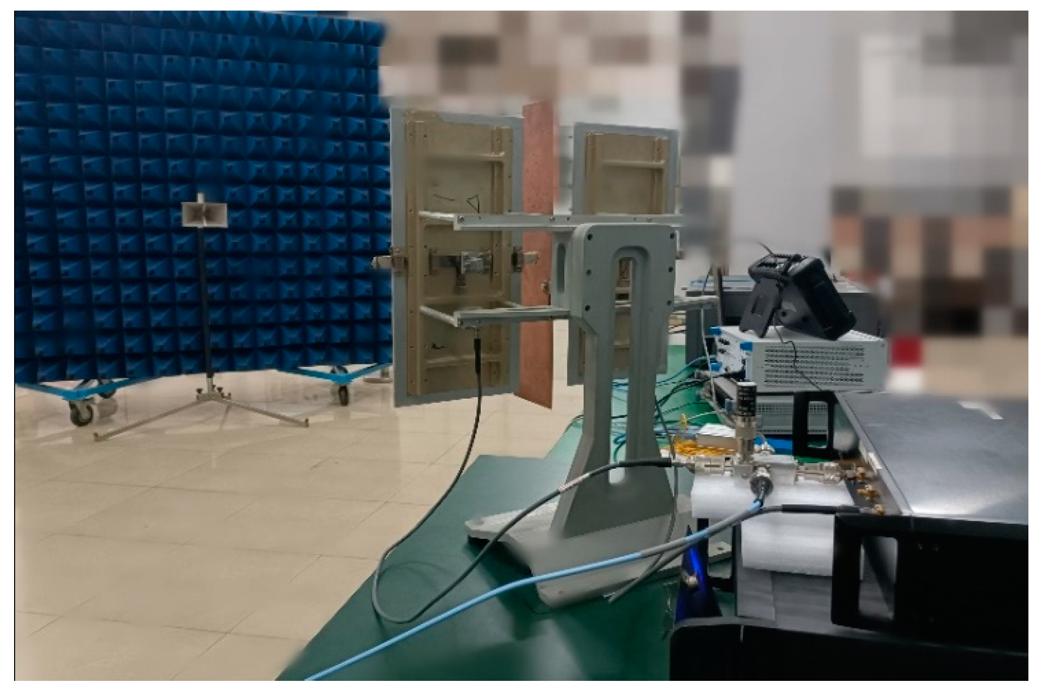
4.1. Pre-Test Preparation
Electromagnetic interference effect test was carried out on the tested radar by electromagnetic injection method. Strictly speaking, electromagnetic injection and irradiation are not completely equivalent, but for the radar test system, electromagnetic interference is mainly coupled to the RF front end by antenna [17,18,19,20,21]. Reference [18] analyzed the radiation equivalent process and test process of the tested equipment in detail, which is not repeated here. The signal source generates the dual-frequency CW interference signal connected to the microwave power amplifier through the combiner, and then the interference signal is injected into the RF front end of the test equipment through the injection module. The spectrometer monitors the input power of the interference signal in real time; the working frequency of the tested radar is f0, the working bandwidth is f0 ± 100 MHz, and the maximum display range of the distance window is 5000 m. The field configuration block diagram is shown in Figure 1.
Figure 1.
Block diagram of field configuration.
The main parameters of the equipment are as follows: The signal generator uses ROHDE & SCHWARZ SMR 20, which can generate 1~20 GHz microwave signal. The power amplifier uses AR 200 T, working frequency band 7.5~18 GHz, and maximum output power 200 W. The directional coupler matched with the power amplifier, and the coupling degree of the forward power monitoring port is 50 dB. The spectrum analyzer uses Agilent company’s E7405A and Ceyear company’s 4204 G, and the frequency ranges are 100 Hz~26.5 GHz and 9 KHz~44 GHz. The target antenna uses BBHA 9120D type dual ridge broadband horn antenna, a frequency range of 1 to 18 GHz, and a gain of 6.3 to 18 dBi. In addition, the method of using the injection coupling module with monitoring function was developed by the team earlier [17].
4.2. Electromagnetic Sensitive Frequency Band Test and Result Analysis of False Alarm Interference
Combining GJB8848-2016 and GJB 151B-2013 [22,23], set the frequency offset of the signal source as , and the one-dimensional range image of the tested radar false alarm signal is shown in Figure 2. According to Equations (10) and (14), the waveform of false alarm signal is broadened due to the existence of secondary phase.
Figure 2.
One-dimensional range image of single frequency electromagnetic interference false alarm signal.
Firstly, combined with the definition of false alarm signal in the early stage, it can be known that the absolute level of false alarm signal is higher than , which is regarded as the effective false alarm level, the electromagnetic sensitivity threshold test has been conducted on the test equipment in the previous period, and the result is shown in Figure 3, which shows that the equipment sensitivity bandwidth is about plus or minus 75 MHz [8]. Therefore, exploring the position of the false alarm signal of the tested radar, set the interference frequency offsets as Δf0 = 0 MHz, Δf1 = −60 MHz, Δf2 = 60 MHz, Δf3 = −75 MHz, Δf4 = 75 MHz corresponding to the position of the false alarm signal as R0, R1, R2, R3, R4, respectively, as shown in Table 2.
Figure 3.
Results of false alarm sensitive threshold of test equipment.
Table 2.
Position of false alarm signal under single frequency electromagnetic interference.
It can be seen from Table 2 that when the Δf0 = 0 MHz, the position R0 of the false alarm signal changes irregularly. Under different interference frequency offsets, the position R of false alarm signal shows the same characteristics. Because the selected frequency points are representative, it is inferred that the position of a single-frequency electromagnetic false alarm signal in the radar band of the tested radar will show similar effect rules. Combined with Equation (14), the initial phase of the local oscillation signal of the tested radar changes irregularly with the detection period k.
4.3. Characteristic Test Results and Analysis of Dual-Frequency Non-Intermodulation False Alarm Interference
Firstly, the waveform characteristics of the false alarm target in the test radar under dual-frequency electromagnetic interference are observed. Set the interference frequency bias Δfj1 = −0 MHz and Δfj2 = 40 MHz of the interference signal, and the one-dimensional distance of the target after detection is obtained as shown in Figure 3.
It can be seen from Figure 4 that two false alarm targets appear when the tested radar is interfered by the in-band dual frequency, and the waveform of the false alarm signal is broadened, which is consistent with the theoretical analysis of Equation (21). Next, analysis the influence of dual frequency electromagnetic interference on false alarm signal position. To distinguish the two interference signals, the field strength difference between the two interference components is set to be more than 6 dB.
Figure 4.
Position of false alarm signal under Δfj1 = 0 MHz and Δfj2 = 40 MHz electromagnetic inter-ference.
The two interfering frequency points are selected with attention to avoid the point of in-band intermodulation. From the previous analysis, it is clear that the unblurred distance corresponding to the tested radar transmitting sub-period is 7500 m, and the tested radar terminal display interface range is up to 5000 m. If the false alarm target position is in 5000~7500, the display interface cannot be observed. The purpose of the experiment is to verify the theoretical analysis results. Therefore, the actual occurrence positions R1′ and R2′ of the two false alarm signals can be recorded when the two false alarm signals are displayed as much as possible through multiple detections, and the results are shown in Table 3.
Table 3.
The position of false alarm signal under Δfj1 = 0.02 kHz and Δfj2 = 3.92 kHz.
It can be seen from Table 3 that dual-frequency electromagnetic interference forms two false alarm signals, and the position of any false alarm signal appears randomly, which is consistent with the analysis of Equations (21) and (25). When two false alarm targets appear, they may not appear in the terminal one-dimensional range image display window. However, when two appear at the same time, in the above ten measurements, the average value is −2898 m when the position appears near −2925 m. By substituting the frequency offset of the two interference signals into Equation (26), the calculated distance difference is −2925 or 4575. The experimental results are in agreement with the theoretical analysis.
Similarly, the interference component 2 frequency bias is increased, and the results are shown in Table 4.
Table 4.
The position of false alarm signal under Δfj1 = 0.02 kHz and Δfj2 = 13.92 kHz.
From Table 4, it can be concluded that when the interference frequency offset increases, in the above ten measurements, the average value is −2935 m when the position appears near −2925 m, and the experimental data is consistent with the theoretical calculation. The test data is consistent with the theoretical calculation results. It shows that the distance value between the dual-frequency non-intermodulation false alarm interference signals of the tested radar under other interference frequency points shows similar characteristics. The test results are consistent with the theoretical analysis.
4.4. Test Results and Analysis of Radar Second-Order Intermodulation False Alarm Interference
The following continue to explore the second-order intermodulation false alarm target location law through the test, as shown in Figure 5 “spike” type second-order intermodulation false alarm signal. Continuous multiple detection records the actual location of the intermodulation signal. The results are shown in Table 5.
Figure 5.
One-dimensional range profile of second-order intermodulation false alarm signal.
Table 5.
Second-order intermodulation signal position under different frequency offset.
According to the Formula (30), calculate the actual appearance position Rc′ of the false alarm signal without considering distance collapse. According to the Formula (21) calculate the false alarm signal position Rt′ after distance folding and compare Rjm2, Rc′, and Rt′. The results are shown in Table 6.
Table 6.
Measured and theoretical data under different frequency offset.
As can be seen from Table 6, when Δfj2 is 1.65 kHz, 3.60 kHz, and 6.60 kHz, the position of second-order intermodulation false alarm signal increases gradually, which is consistent with R theory calculated by Equation (30). As the value of interference frequency offset Δfj2 continues to increase, the target position of second-order intermodulation false alarm seems to decrease gradually and then increase. According to the research content on distance “reentry” in literature [16], when the false alarm signal exceeds the sub-period non-fuzzy distance value of 7500 m, the ‘retrace’ occurs. After the original distance value is calculated according to the theoretical equation, the final value is the actual position of the second-order intermodulation false alarm intermodulation according to the unambiguous distance corresponding to the sub-period. Comparing the measured Rav with the Rt′ theory, it can be seen that the experimental results are consistent with the theoretical analysis. The test data are stable, with small relative error and good repeatability, the test equipment does not appear dead, and restarted during the test.
5. Conclusions
This paper takes a stepped frequency radar as the research object. Firstly, use the stretch processing method to decouple the radar received signal in time and frequency, distinguish the target echo signal from false alarm interference signal, and analyze the target characteristics of false alarm interference theoretically. Secondly, from the perspective of receiver mixing, the target echo signal and false alarm interference signal are distinguished, and the imaging characteristics of single-frequency, dual-frequency non-intermodulation, and second-order intermodulation false alarm signals are analyzed. Finally, the electromagnetic interference test of the tested radar is carried out by the electromagnetic injection method. The following conclusions are drawn:
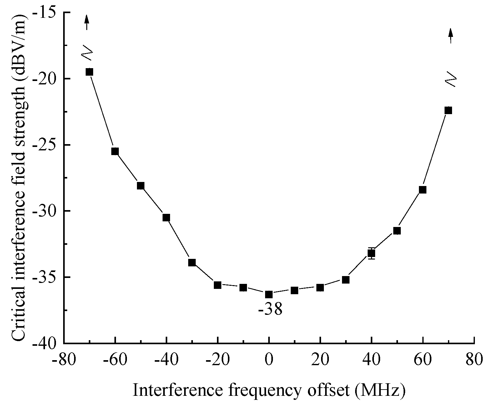
- The electromagnetic sensitive bandwidth of the false alarm signal is about ±75 MHz, which is smaller than its working bandwidth.
- The position of the single-frequency electromagnetic false alarm interference signal of the tested radar is affected by the local oscillator phase, and the position shows random performance.
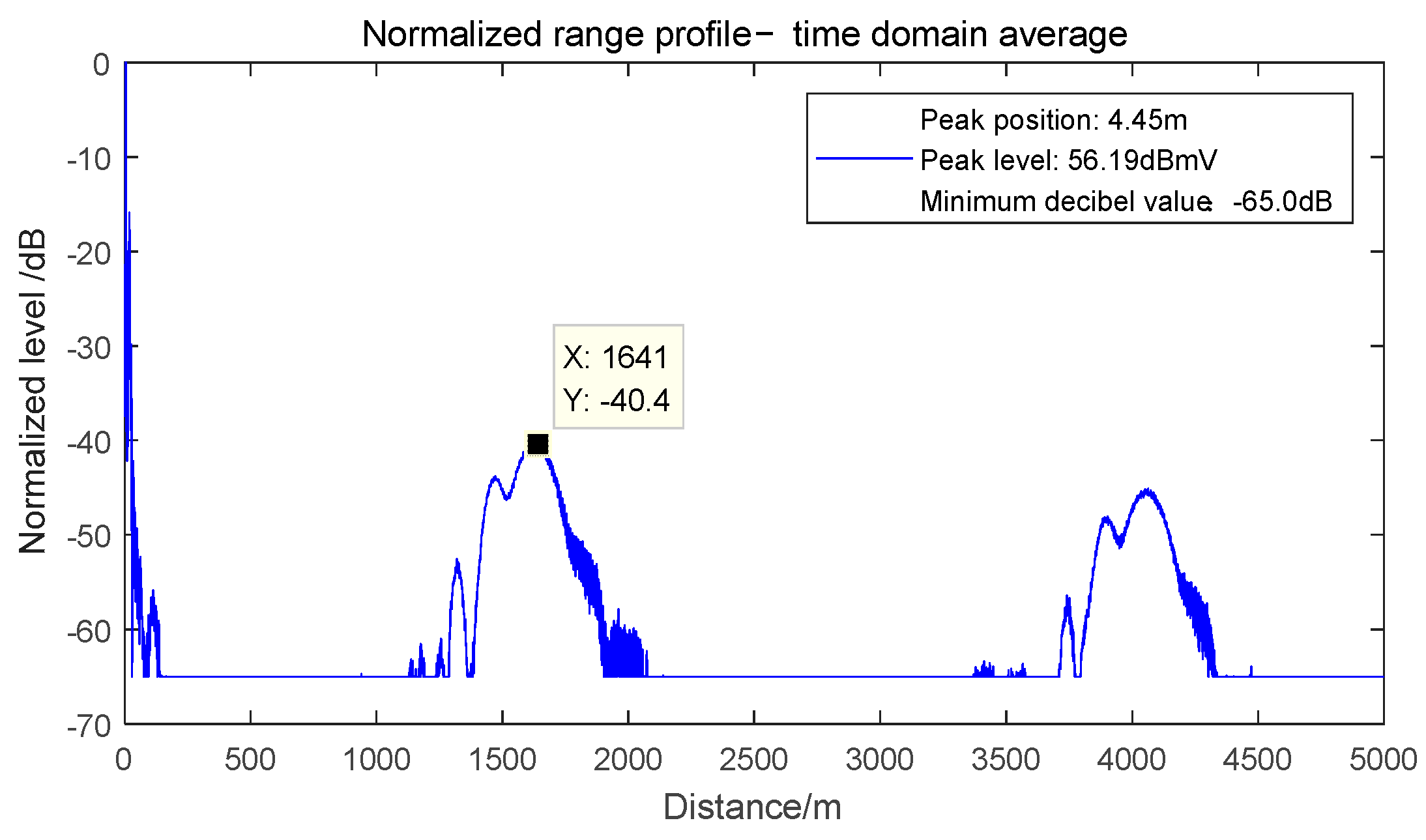
- Without considering the intermodulation, the dual-frequency electromagnetic interference makes the test radar generate two false alarm signals with wide waveform. The dual frequency non-intermodulation false alarm signal distance difference is related to the interference frequency difference. Under the condition of tight constraints, the frequency offset of dual-frequency interference can be substituted into the test radar according to Formula (26) to obtain the distance difference between the two false alarm targets of −2925 m and 4575 m, and the test results are consistent with the theory.
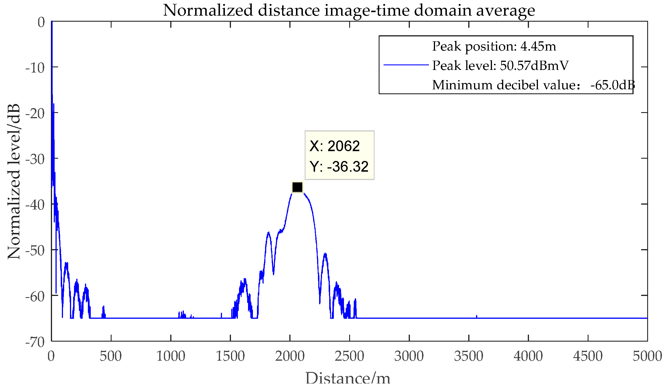
- The second-order intermodulation false alarm signal is ‘spike’ shaped; its position is related to the frequency offset of dual-frequency interference, the relative error is less than 0.1, and the test data is stable.
6. Discussion
Firstly, through the study of the electromagnetic interference false alarm signal, it is found that the radar is affected by external electromagnetic interference. When the frequency offset of the interference signal is close to the frequency of the working signal, the interference signal and the useful signal enter the receiver and participate in the process of mixing, amplification, and filtering. Next, the false alarm signal is generated by signal processing, which affects the judgment of the received signal. When the deviation range between dual-frequency electromagnetic interference is small to a certain extent, it will produce second-order intermodulation false alarm interference, which also affects the judgment of target echo signal. Although many scholars have proposed corresponding anti-interference algorithms for radar external electromagnetic interference, due to the characteristics of radar itself, the signal frequency after mixing may not be fixed, which makes the filter unable to effectively filter out the interference signal. This paper analyzes the law of false alarm interference position of the tested radar, which provides strong support for the modeling of multi-frequency electromagnetic false alarm interference in the next step.
Secondly, when the interference frequency is close to the operating frequency, in addition to generating second-order low-frequency intermodulation interference, the mixing frequency will also generate third-order intermodulation false alarm signals. The third-order intermodulation false alarm signal target characteristics and position change law are the next planned focuses.
In practical applications, when the external interference increases to a certain degree, the nonlinearity of the device will cause the radar to generate false alarm signals while suppressing the target echo level, and the generation of higher-order intermodulation false alarm signals will affect the capture of real target signals, so it is necessary to conduct a detailed study to explain the intermodulation false alarm signals and establish a multifrequency electromagnetic false alarm interference signal model on this basis to explore the radar equipment. This is also the focus of the next work.
Author Contributions
X.D. conceived of the study, designed the study, and wrote the manuscript. G.W. provides guidance on ideas and mathematical treatment. K.Z. and H.Z. compiled the experimental data. X.L. assisted in the editing of manuscripts. All authors have read and agreed to the published version of the manuscript.
Funding
This work was supported by the National Science Foundation of Key national Defense basic Research projects (41409030301).
Informed Consent Statement
Written informed consent has been obtained from the patient(s) to publish this paper.
Data Availability Statement
The authors confirm that the data supporting the findings of this study are available within the article.
Conflicts of Interest
The authors declare that they have no conflict of interest regarding the publication of this paper.
References
- Zou, L.; Wang, X.T.; Wang, W. Ku-Band High Performance Monopulse Microstrip Array Antenna Based on Waveguide Coupling Slot Array Feeding Network. Radioengineering 2020, 29, 59–66. [Google Scholar] [CrossRef]
- Tang, Z.Y.; Yu, C.R.; Deng, Y.K. Evaluation of Deceptive Jamming Effect on SAR Based on Visual Consistency. IEEE J. Sel. Top. Appl. Earth Obs. Remote Sens. 2022, 11, 12246–12262. [Google Scholar] [CrossRef]
- Du, X.; Wei, G.H.; Zhao, K. Study on Electromagnetic Sensitivity of Ku-band Stepped Frequency Radar. In Proceedings of the 13th Global Symposium on Millimeter-Waves & Terahertz (GSMM), Nanjing, China, 23–26 May 2021; Volume 5, pp. 1–3. [Google Scholar]
- Wang, L.; Shen, X.; Zhou, B. Review on cognition of complex electromagnetic environment. Aerosp. Electron. Warf. 2020, 36, 1–6. [Google Scholar]
- Du, X.; Wei, G.H.; Ren, S.Z.; Zhao, K. Analysis of Blocking Effect of Single Frequency Continuous Wave Electromagnetic Radiation in Swept Frequency Radar. Syst. Eng. Electron. 2020, 42, 2742–2746. [Google Scholar]
- Zhao, K.; Wei, G. Dual frequency blocking interference laws with high order nonlinear distortion. Syst. Eng. Electron. 2021, 32, 61–66. [Google Scholar]
- Zhao, K.; Wei, G.H.; Wang, Y.P. Prediction model of in-band blocking interference under the electromagnetic radiation of dual-frequency continuous wave. Int. J. Antennasand Propag. 2020, 2, 1–8. [Google Scholar] [CrossRef]
- Du, X. Research on Continuous Wave Electromagnetic Effect in Swept Frequency Radar. Math. Probl. Eng. 2021, 2021, 4862451. [Google Scholar] [CrossRef]
- Liu, Y.; Zhang, Q.; Liu, Z.; Li, G.; Xiong, S.; Luo, Y. An Anti-Jamming Method against Interrupted Sampling Repeater Jamming Based on Compressed Sensing. Sensors 2022, 22, 2239. [Google Scholar] [CrossRef] [PubMed]
- Olivier, K.; Cilliers, J.E. Design and performance of wideband DRFM for radar test and evaluation. Electron. Lett. 2011, 47, 824–825. [Google Scholar] [CrossRef] [Green Version]
- Hill, P.C.; Truffert, V. Statistical processing techniques for detecting DRFM repeat-jamradar signals. Signal Process. Tech. Electron. Warf. IEE Colloq. 1992, 2, 1–6. [Google Scholar]
- Weng, Y.X. Simultaneous Multi-target Interference Technology Based on Digital Reconfigurability. J. Caeit 2019, 14, 1270–1275. [Google Scholar]
- Lu, G.; Tang, B. Deception jammer rejection using pulse diversity in joint slow/fast-time domain. J. Chin. Inst. Eng. 2013, 36, 405–410. [Google Scholar] [CrossRef]
- Li, W.; Huang, F.; Yang, H.M. Efficiency Analysis of adar Noise Jamming and Multiple. J. CAEIT 2013, 8, 403–406. [Google Scholar]
- Li, D.; Long, T. Target’s Redundance Removed Algorithms of Step Frequency Radar. Acta Electron. Sin. 2000, 28, 60–64. [Google Scholar]
- Long, T.; Li, D.; Wu, Q. Design Methods for Step Frequency Waveform and the Target Pick-up Algorithm. Syst. Eng. Electron. 2001, 23, 26–31. [Google Scholar]
- Lu, X.F.; Wei, G.H.; Pan, X.D. A directional coupler based injection device aimed at radiated susceptibility verification of antenna systems against HIRF. J. Electromagn. Waves Appl. 2013, 27, 1351–1364. [Google Scholar] [CrossRef]
- Lu, X.F.; Wei, G.H.; Pan, X.D. A double differential-mode current injection method based on directional couplers for HIRF verification testing of interconnected systems. J. Electromagn. Waves Appl. 2014, 28, 346–359. [Google Scholar] [CrossRef]
- Xu, T.; Chen, Y.Z.; Wang, Y.M.; Zhao, M. Research on In-band Continuous Wave Electromagnetic Interference Effect of UAV Data Link. Trans. Beijing Inst. Technol. 2021, 41, 1084–1094. [Google Scholar]
- Fan, Y.; Cheng, E.; Wei, M.; Zhang, Q.; Chen, Y. Effects of CW interference on the BDS receiver and analysis on the coupling path of electromagnetic energy. IEEE Access 2019, 7, 155885–155893. [Google Scholar] [CrossRef]
- Du, X.; Wei, G.; Zhao, H. Research on the Continuous Wave Electromagnetic Environmental Effect of Radar Equipment. J. Army Eng. Univ. PLA 2022, 1, 1–8. [Google Scholar]
- GJB8848-2016; Electromagnetic Environmental Effects Test Methods for Systems. Equipment Development Department of the Central Military Commission: Beijing, China, 2016.
- GJB 151B-2013; Electromagnetic Emission and Susceptibility Requirements and Measurements for Military Equipment and Subsystems. Military Standard Press of General Equipment Department: Beijing, China, 2013.
Publisher’s Note: MDPI stays neutral with regard to jurisdictional claims in published maps and institutional affiliations. |
© 2022 by the authors. Licensee MDPI, Basel, Switzerland. This article is an open access article distributed under the terms and conditions of the Creative Commons Attribution (CC BY) license (https://creativecommons.org/licenses/by/4.0/).