
Spoofing Attacks on FMCW Radars with Low-Cost Backscatter Tags


Abstract
:
1. Introduction
1.1. Background and Motivation
1.2. Related Work
1.3. Contribution
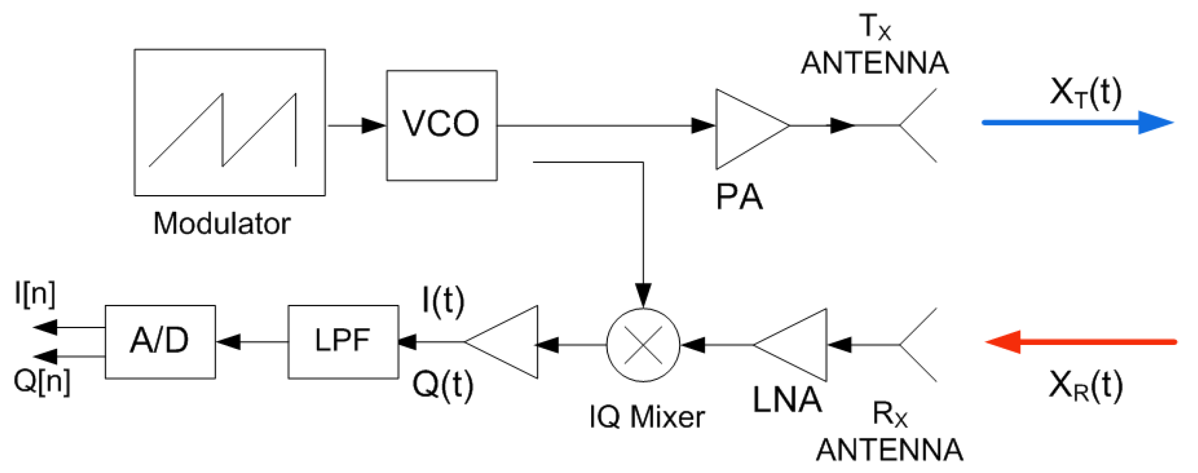
2. System Overview and Theoretical Background
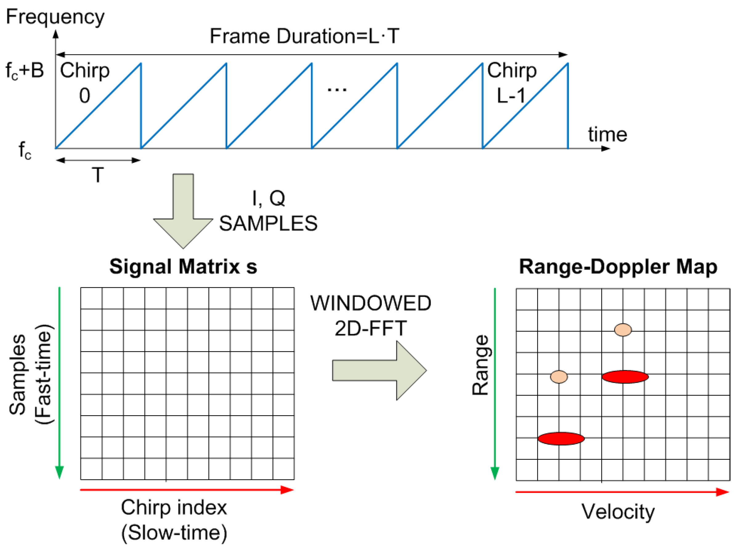
FMCW Radar and Backscatter Detection
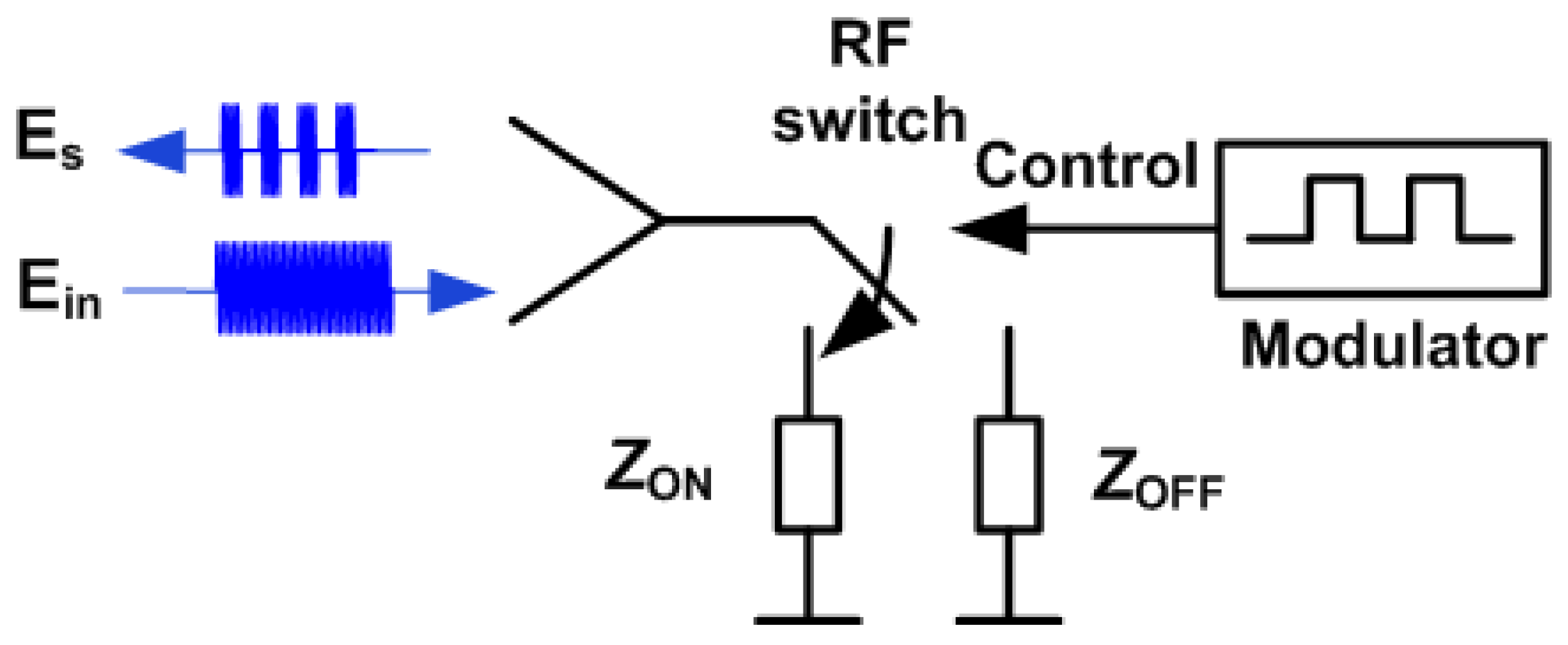
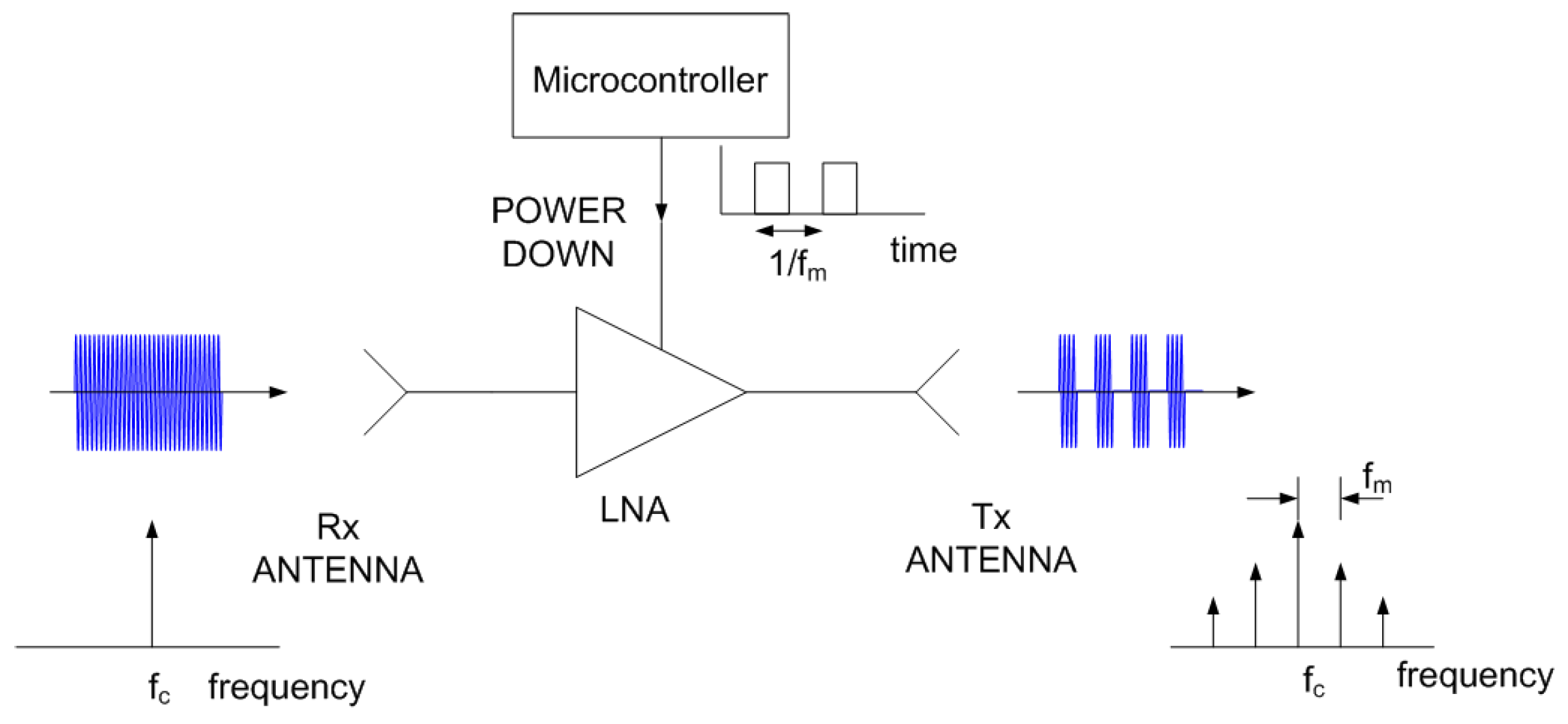
3. Spoofing Device Design
4. Results
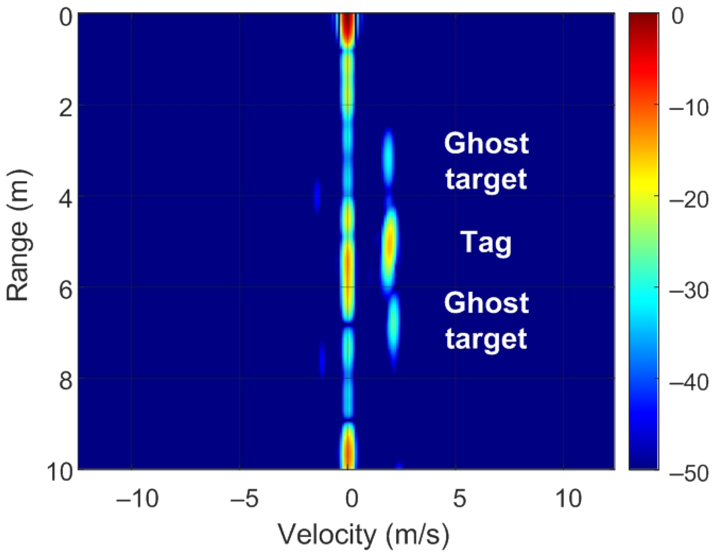
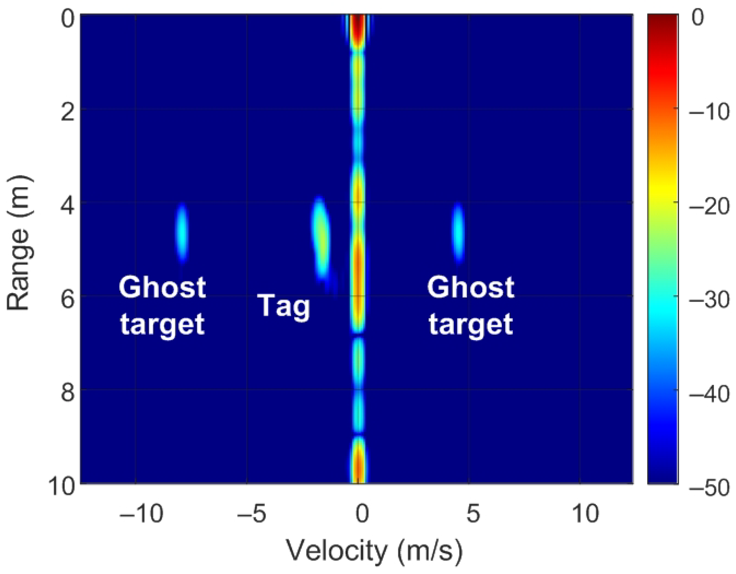
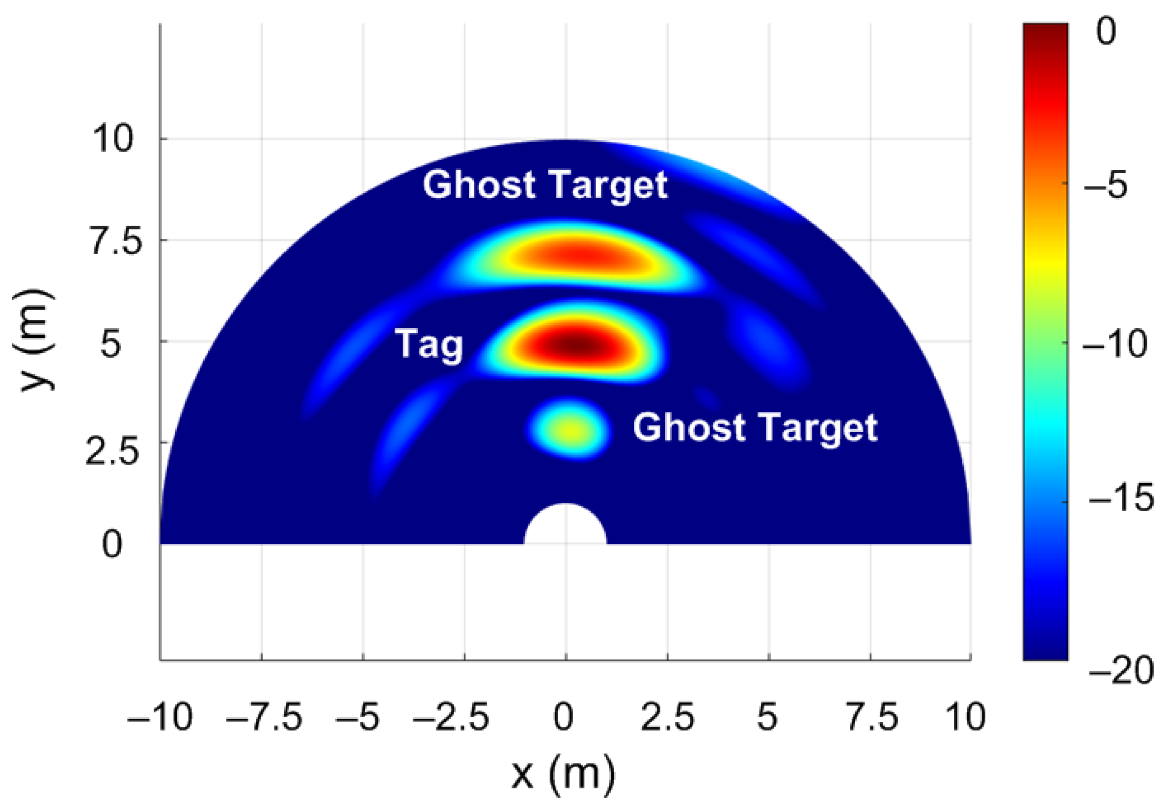
4.1. Simulated Results
4.2. Experimental Validation
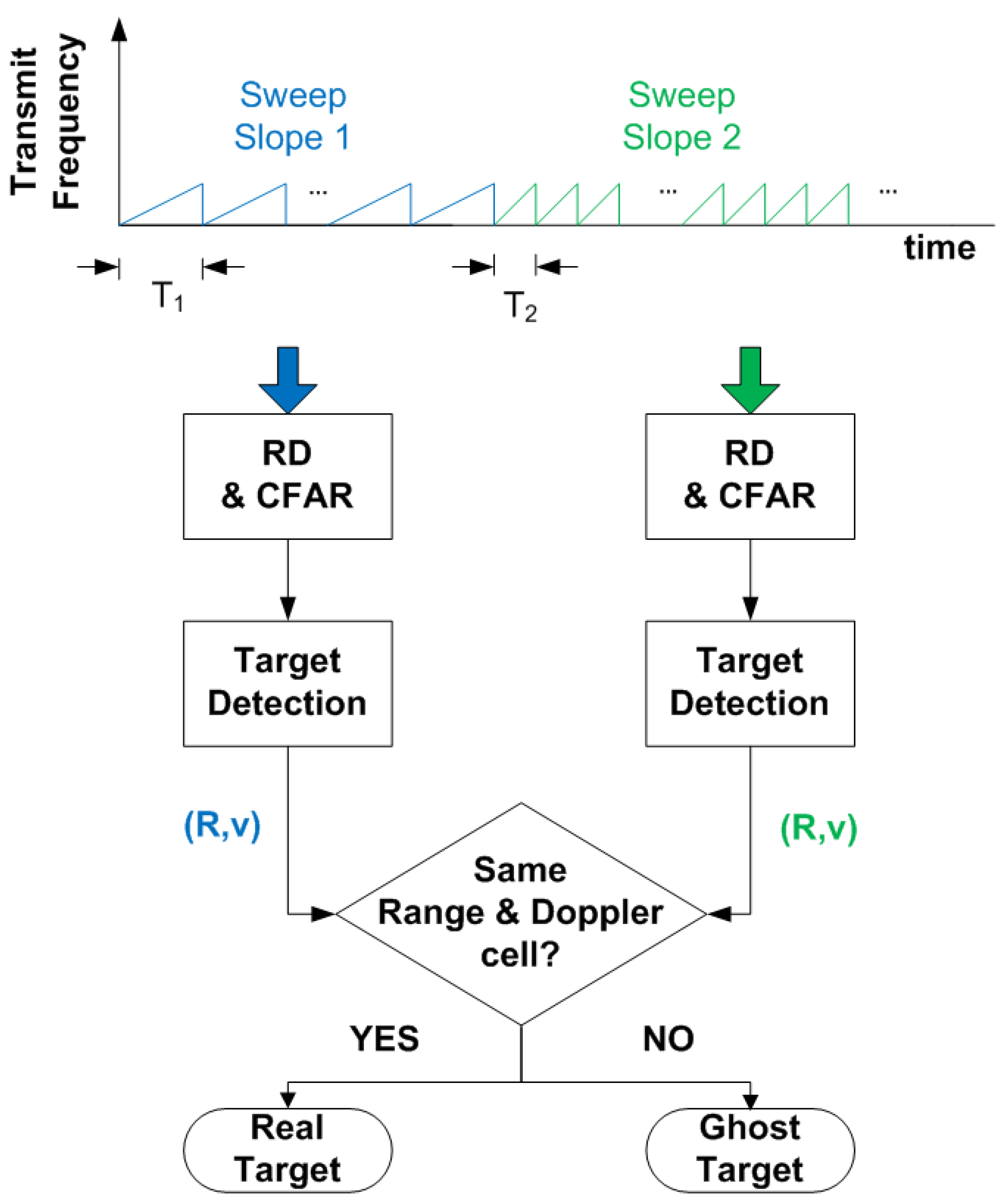
5. Discussion and Countermeasures
6. Conclusions and Future Work
Author Contributions
Funding
Institutional Review Board Statement
Informed Consent Statement
Data Availability Statement
Conflicts of Interest
References
- Park, J.; Park, S.; Kim, D.H.; Park, S.O. Leakage mitigation in heterodyne FMCW radar for small drone detection with stationary point concentration technique. IEEE Trans. Microw. Theory Tech. 2019, 67, 1221–1232. [Google Scholar] [CrossRef] [Green Version]
- Alizadeh, M.; Shaker, G.; De Almeida, J.C.M.; Morita, P.P.; Safavi-Naeini, S. Remote monitoring of human vital signs using mm-wave FMCW radar. IEEE Access 2019, 7, 54958–54968. [Google Scholar] [CrossRef]
- Piotrowsky, L.; Jaeschke, T.; Kueppers, S.; Siska, J.; Pohl, N. Enabling high accuracy distance measurements with FMCW radar sensors. IEEE Trans. Microw. Theory Tech. 2019, 67, 5360–5371. [Google Scholar] [CrossRef]
- Shrestha, A.; Li, H.; Le Kernec, J.; Fioranelli, F. Continuous human activity classification from FMCW radar with Bi-LSTM networks. IEEE Sens. J. 2020, 20, 13607–13619. [Google Scholar] [CrossRef]
- Wang, Y.; Ren, A.; Zhou, M.; Wang, W.; Yang, X. A novel detection and recognition method for continuous hand gesture using fmcw radar. IEEE Access 2020, 8, 167264–167275. [Google Scholar] [CrossRef]
- Alizadeh, M.; Abedi, H.; Shaker, G. Low-cost low-power in-vehicle occupant detection with mm-wave FMCW radar. In Proceedings of the 2019 IEEE SENSORS, Montreal, QC, Canada, 27–30 October 2019; pp. 1–4. [Google Scholar]
- Rasshofer, R.H.; Spies, M.; Spies, H. Influences of weather phenomena on automotive laser radar systems. Adv. Radio Sci. ARS 2011, 9, 49. [Google Scholar] [CrossRef] [Green Version]
- Sun, S.; Petropulu, A.P.; Poor, H.V. MIMO radar for advanced driver-assistance systems and autonomous driving: Advantages and challenges. IEEE Signal Process. Mag. 2020, 37, 98–117. [Google Scholar] [CrossRef]
- Currie, N.C.; Brown, C.E. Principles and Applications of Millimeter-Wave Radar; Artech House Norwood: Norwood, MA, USA, 1987. [Google Scholar]
- Poisel, R. Modern Communications Jamming Principles and Techniques; Artech House: Norwood, MA, USA, 2011. [Google Scholar]
- Gerstmair, M.; Melzer, A.; Onic, A.; Huemer, M. On the safe road toward autonomous driving: Phase noise monitoring in radar sensors for functional safety compliance. IEEE Signal Process. Mag. 2019, 36, 60–70. [Google Scholar] [CrossRef]
- Jin, F.; Cao, S. Automotive Radar Interference Mitigation Using Adaptive Noise Canceller. IEEE Trans. Veh. Technol. 2019, 68, 3747–3754. [Google Scholar] [CrossRef] [Green Version]
- Graham, A. Communications, Radar and Electronic Warfare; John Wiley & Sons: Hoboken, NJ, USA, 2011. [Google Scholar]
- Lichtman, M.; Poston, J.D.; Amuru, S.; Shahriar, C.; Clancy, T.C.; Buehrer, R.M.; Reed, J.H. A communications jamming taxonomy. IEEE Secur. Priv. 2016, 14, 47–54. [Google Scholar] [CrossRef]
- Schroer, R. Electronic warfare. [A century of powered flight: 1903–2003]. IEEE Aerosp. Electron. Syst. Mag. 2003, 18, 49–54. [Google Scholar] [CrossRef]
- Matić, V.; Kosjer, V.; Lebl, A.; Pavić, B.; Radivojević, J. Methods for Drone Detection and Jamming. In Proceedings of the 10th International Conference on Information Society and Technology (ICIST), Kopaonik, Serbia, 8–11 March 2020; pp. 16–21. [Google Scholar]
- Tedeschi, P.; Oligeri, G.; Di Pietro, R. Leveraging jamming to help drones complete their mission. IEEE Access 2019, 8, 5049–5064. [Google Scholar] [CrossRef]
- Wang, Y.; Zhan, Z.; Xue, B. Operation method of electronic warfare UAV. In Proceedings of the Global Intelligence Industry Conference (GIIC 2018), International Society for Optics and Photonics, Beijing, China, 22–24 May 2018; Volume 10835, p. 108351L. [Google Scholar]
- Multerer, T.; Ganis, A.; Prechtel, U.; Miralles, E.; Meusling, A.; Mietzner, J.; Vossiek, M.; Loghi, M.; Ziegler, V. Low-cost jamming system against small drones using a 3D MIMO radar based tracking. In Proceedings of the 2017 European Radar Conference (EURAD), Nuremberg, Germany, 11–13 October 2017; pp. 299–302. [Google Scholar]
- Yan, C.; Xu, W.; Liu, J. Can you trust autonomous vehicles: Contactless attacks against sensors of self-driving vehicle. DEFCON 2016, 24, 109. [Google Scholar]
- Yeh, E.; Choi, J.; Prelcic, N.; Bhat, C.; Heath, R.W., Jr. Security in automotive radar and vehicular networks. Microw. J. 2016. submitted. [Google Scholar]
- Wagner, M.; Sulejmani, F.; Melzer, A.; Meissner, P.; Huemer, M. Threshold-Free Interference Cancellation Method for Automotive FMCW Radar Systems. In Proceedings of the 2018 IEEE International Symposium on Circuits and Systems (ISCAS), Florence, Italy, 27–30 May 2018; pp. 1–4. [Google Scholar] [CrossRef]
- Brooker, G.M. Mutual interference of millimeter-wave radar systems. IEEE Trans. Electromagn. Compat. 2007, 49, 170–181. [Google Scholar] [CrossRef]
- Uysal, F. Phase-coded FMCW automotive radar: System design and interference mitigation. IEEE Trans. Veh. Technol. 2019, 69, 270–281. [Google Scholar] [CrossRef] [Green Version]
- Dai, J.; Hao, X.; Li, P.; Li, Z.; Yan, X. Antijamming design and analysis of a novel pulse compression radar signal based on radar identity and chaotic encryption. IEEE Access 2020, 8, 5873–5884. [Google Scholar] [CrossRef]
- Alland, S.; Stark, W.; Ali, M.; Hegde, M. Interference in automotive radar systems: Characteristics, mitigation techniques, and current and future research. IEEE Signal Process. Mag. 2019, 36, 45–59. [Google Scholar] [CrossRef]
- Bechter, J.; Eid, K.; Roos, F.; Waldschmidt, C. Digital beamforming to mitigate automotive radar interference. In Proceedings of the 2016 IEEE MTT-S International Conference on Microwaves for Intelligent Mobility (ICMIM), San Diego, CA, USA, 19–20 May 2016; pp. 1–4. [Google Scholar]
- Bechter, J.; Rameez, M.; Waldschmidt, C. Analytical and experimental investigations on mitigation of interference in a DBF MIMO radar. IEEE Trans. Microw. Theory Tech. 2017, 65, 1727–1734. [Google Scholar] [CrossRef]
- Chauhan, R. A Platform for False Data Injection in Frequency Modulated Continuous Wave Radar; Utah State University: Logan, UT, USA, 2014. [Google Scholar]
- Shoukry, Y.; Martin, P.; Yona, Y.; Diggavi, S.; Srivastava, M. Pycra: Physical challenge-response authentication for active sensors under spoofing attacks. In Proceedings of the 22nd ACM SIGSAC Conference on Computer and Communications Security, Denver, CO, USA, 12–16 October 2015; pp. 1004–1015. [Google Scholar]
- Dutta, R.G.; Guo, X.; Zhang, T.; Kwiat, K.; Kamhoua, C.; Njilla, L.; Jin, Y. Estimation of safe sensor measurements of autonomous system under attack. In Proceedings of the 54th Annual Design Automation Conference 2017, Austin, TX, USA, 18–22 June 2017; pp. 1–6. [Google Scholar]
- Kapoor, P.; Vora, A.; Kang, K.D. Detecting and Mitigating Spoofing Attack Against an Automotive Radar. In Proceedings of the 2018 IEEE 88th Vehicular Technology Conference (VTC-Fall), Chicago, IL, USA, 27–30 August 2018; pp. 1–6. [Google Scholar] [CrossRef]
- Komissarov, R.; Wool, A. Spoofing attacks against vehicular FMCW radar. In Proceedings of the 5th Workshop on Attacks and Solutions in Hardware Security, Virtual Event, Korea, 19 November 2021; pp. 91–97. [Google Scholar]
- Toker, O.; Alsweiss, S. Design of a cyberattack resilient 77 GHz automotive radar sensor. Electronics 2020, 9, 573. [Google Scholar] [CrossRef] [Green Version]
- Miura, N.; Machida, T.; Matsuda, K.; Nagata, M.; Nashimoto, S.; Suzuki, D. A low-cost replica-based distance-spoofing attack on mmWave FMCW radar. In Proceedings of the 3rd ACM Workshop on Attacks and Solutions in Hardware Security Workshop, London, UK, 15 November 2019; pp. 95–100. [Google Scholar]
- Moon, T.; Park, J.; Kim, S. BlueFMCW: Random frequency hopping radar for mitigation of interference and spoofing. EURASIP J. Adv. Signal Process. 2022, 2022, 1–17. [Google Scholar] [CrossRef]
- Li, C.; Cummings, J.; Lam, J.; Graves, E.; Wu, W. Radar remote monitoring of vital signs. IEEE Microw. Mag. 2009, 10, 47–56. [Google Scholar] [CrossRef]
- Nallabolu, P.; Li, C. A Frequency-Domain Spoofing Attack on FMCW Radars and Its Mitigation Technique Based on a Hybrid-Chirp Waveform. IEEE Trans. Microw. Theory Tech. 2021, 69, 5086–5098. [Google Scholar] [CrossRef]
- Nashimoto, S.; Suzuki, D.; Miura, N.; Machida, T.; Matsuda, K.; Nagata, M. Low-cost distance-spoofing attack on FMCW radar and its feasibility study on countermeasure. J. Cryptogr. Eng. 2021, 11, 289–298. [Google Scholar] [CrossRef]
- Rodriguez, D.; Wang, J.; Li, C. Spoofing attacks to radar motion sensors with portable RF devices. In Proceedings of the 2021 IEEE Radio and Wireless Symposium (RWS), San Diego, CA, USA, 17–22 January 2021; pp. 73–75. [Google Scholar]
- Guvenc, I.; Koohifar, F.; Singh, S.; Sichitiu, M.L.; Matolak, D. Detection, tracking, and interdiction for amateur drones. IEEE Commun. Mag. 2018, 56, 75–81. [Google Scholar] [CrossRef]
- Zhao, J.; Fu, X.; Yang, Z.; Xu, F. Radar-assisted UAV detection and identification based on 5G in the Internet of Things. Wirel. Commun. Mob. Comput. 2019, 2019, 2850263. [Google Scholar] [CrossRef] [Green Version]
- Lykou, G.; Moustakas, D.; Gritzalis, D. Defending airports from UAS: A survey on cyber-attacks and counter-drone sensing technologies. Sensors 2020, 20, 3537. [Google Scholar] [CrossRef] [PubMed]
- Wang, J.; Liu, Y.; Song, H. Counter-unmanned aircraft system (s)(C-UAS): State of the art, challenges, and future trends. IEEE Aerosp. Electron. Syst. Mag. 2021, 36, 4–29. [Google Scholar] [CrossRef]
- Matos, D.; da Cruz Jordão, M.D.; Correia, R.; Carvalho, N.B. Millimeter-Wave BiCMOS Backscatter Modulator for 5G-IoT Applications. IEEE Microw. Wirel. Components Lett. 2020, 31, 173–176. [Google Scholar] [CrossRef]
- Eid, A.; Hester, J.G.; Tentzeris, M.M. Rotman Lens-Based Wide Angular Coverage and High-Gain Semipassive Architecture for Ultralong Range mm-Wave RFIDs. IEEE Antennas Wirel. Propag. Lett. 2020, 19, 1943–1947. [Google Scholar] [CrossRef]
- Daskalakis, S.; Georgiadis, A.; Kimionis, J.; Tentzeris, M. A printed millimeter-wave modulator and antenna array for low-complexity Gigabit-datarate backscatter communications. Res. Sq. 2021. [Google Scholar] [CrossRef]
- Schmid, C.M.; Feger, R.; Stelzer, A. Millimeter-wave phase-modulated backscatter transponder for FMCW radar applications. In Proceedings of the 2011 IEEE MTT-S International Microwave Symposium, Baltimore, MD, USA, 5–10 June 2011; pp. 1–4. [Google Scholar]
- Stein, W.; Aleksieieva, A.; Roehr, S.; Vossiek, M. Phase modulated 61 GHz backscatter transponder for FMCW radar-based ranging. In Proceedings of the GeMiC 2014; German Microwave Conference, Aachen, Germany, 10–12 March 2014; pp. 1–4. [Google Scholar]
- Lazaro, A.; Lorenzo, J.; Villarino, R.; Girbau, D. Backscatter transponder based on frequency selective surface for FMCW radar applications. Radioengineering 2014, 23, 632–641. [Google Scholar]
- Lazaro, A.; Ramos, A.; Girbau, D.; Villarino, R. A novel UWB RFID tag using active frequency selective surface. IEEE Trans. Antennas Propag. 2012, 61, 1155–1165. [Google Scholar] [CrossRef]
- Kim, B.; Kim, S.; Lee, J. A novel DFT-based DOA estimation by a virtual array extension using simple multiplications for FMCW radar. Sensors 2018, 18, 1560. [Google Scholar] [CrossRef] [PubMed] [Green Version]
- Collin, R. Limitations of the Thevenin and Norton equivalent circuits for a receiving antenna. IEEE Antennas Propag. Mag. 2003, 45, 119–124. [Google Scholar] [CrossRef]
- Green, R.B. The General Theory of Antenna Scattering; The Ohio State University: Columbus, OH, USA, 1963. [Google Scholar]
- Nikitin, P.V.; Rao, K.S.; Lam, S.F.; Pillai, V.; Martinez, R.; Heinrich, H. Power reflection coefficient analysis for complex impedances in RFID tag design. IEEE Trans. Microw. Theory Tech. 2005, 53, 2721–2725. [Google Scholar] [CrossRef]
- Rohling, H.; Kronauge, M. New radar waveform based on a chirp sequence. In Proceedings of the 2014 International Radar Conference, Lille, France, 13–17 October 2014; pp. 1–4. [Google Scholar] [CrossRef]
- Lazaro, A.; Lazaro, M.; Villarino, R.; De Paco, P. New Radar Micro-Doppler Tag for Road Safety Based on the Signature of Rotating Backscatters. IEEE Sens. J. 2020, 21, 8604–8612. [Google Scholar] [CrossRef]
- Harris, F.J. On the use of windows for harmonic analysis with the discrete Fourier transform. Proc. IEEE 1978, 66, 51–83. [Google Scholar] [CrossRef]
- Lazaro, A.; Lazaro, M.; Villarino, R.; Girbau, D.; de Paco, P. Car2Car Communication Using a Modulated Backscatter and Automotive FMCW Radar. Sensors 2021, 21, 3656. [Google Scholar] [CrossRef] [PubMed]
- Lazaro, A.; Villarino, R.; Lazaro, M.; Girbau, D.; dePaco, P. Modulated Backscattering transponder to increase the detectability of pedestrians with automotive radar at 24 GHz. In Proceedings of the 2021 XXXIVth General Assembly and Scientific Symposium of the International Union of Radio Science (URSI GASS), Rome, Italy, 28 August–4 September 2021; pp. 1–4. [Google Scholar]
- Filipovic, D.F.; Gearhart, S.S.; Rebeiz, G.M. Double-slot antennas on extended hemispherical and elliptical silicon dielectric lenses. IEEE Trans. Microw. Theory Tech. 1993, 41, 1738–1749. [Google Scholar] [CrossRef]
- Nguyen, N.T.; Rolland, A.; Boriskin, A.V.; Valerio, G.; Le Coq, L.; Sauleau, R. Size and weight reduction of integrated lens antennas using a cylindrical air cavity. IEEE Trans. Antennas Propag. 2012, 60, 5993–5998. [Google Scholar] [CrossRef]
- Kamran Saleem, M.; Xie, M.; Alkanhal, M.A.; Saadi, M. Effect of dielectric materials on integrated lens antenna for millimeter wave applications. Microw. Opt. Technol. Lett. 2019, 61, 1079–1083. [Google Scholar] [CrossRef]
- Boussatour, G.; Cresson, P.Y.; Genestie, B.; Joly, N.; Lasri, T. Dielectric characterization of polylactic acid substrate in the frequency band 0.5–67 GHz. IEEE Microw. Wirel. Components Lett. 2018, 28, 374–376. [Google Scholar] [CrossRef]
- Garg, R.; Bhartia, P.; Bahl, I.J.; Ittipiboon, A. Microstrip Antenna Design Handbook; Artech House: Norwood, MA, USA, 2001. [Google Scholar]
- Marchetti, E.; Du, R.; Norouzian, F.; Hoare, E.; Tran, T.Y.; Cherniakov, M.; Gashinova, M. Comparison of pedestrian reflectivities at 24 and 300 GHz. In Proceedings of the 2017 18th International Radar Symposium (IRS), Prague, Czech Republic, 28–30 June 2017; pp. 1–7. [Google Scholar]
- Schipper, T.; Fortuny-Guasch, J.; Tarchi, D.; Reichardt, L.; Zwick, T. RCS measurement results for automotive related objects at 23–27 GHz. In Proceedings of the 5th European Conference on Antennas and Propagation (EUCAP), Rome, Italy, 11–15 April 2011; pp. 683–686. [Google Scholar]
- Lin, J.; Chien, S.; Chen, Y.; Chen, C.C.; Sherony, R. 24 GHz and 77 GHz radar characteristics of metal guardrail for the development of metal guardrail surrogate for road departure mitigation system testing. In Proceedings of the 2019 IEEE Intelligent Transportation Systems Conference (ITSC), Auckland, New Zealand, 27–30 October 2019; pp. 3340–3346. [Google Scholar]
- Abou-Khousa, M.A.; Simms, D.L.; Kharkovsky, S.; Zoughi, R. High-resolution short-range wideband FMCW radar measurements based on MUSIC algorithm. In Proceedings of the 2009 IEEE Instrumentation and Measurement Technology Conference, Singapore, 5–7 May 2009; pp. 498–501. [Google Scholar]


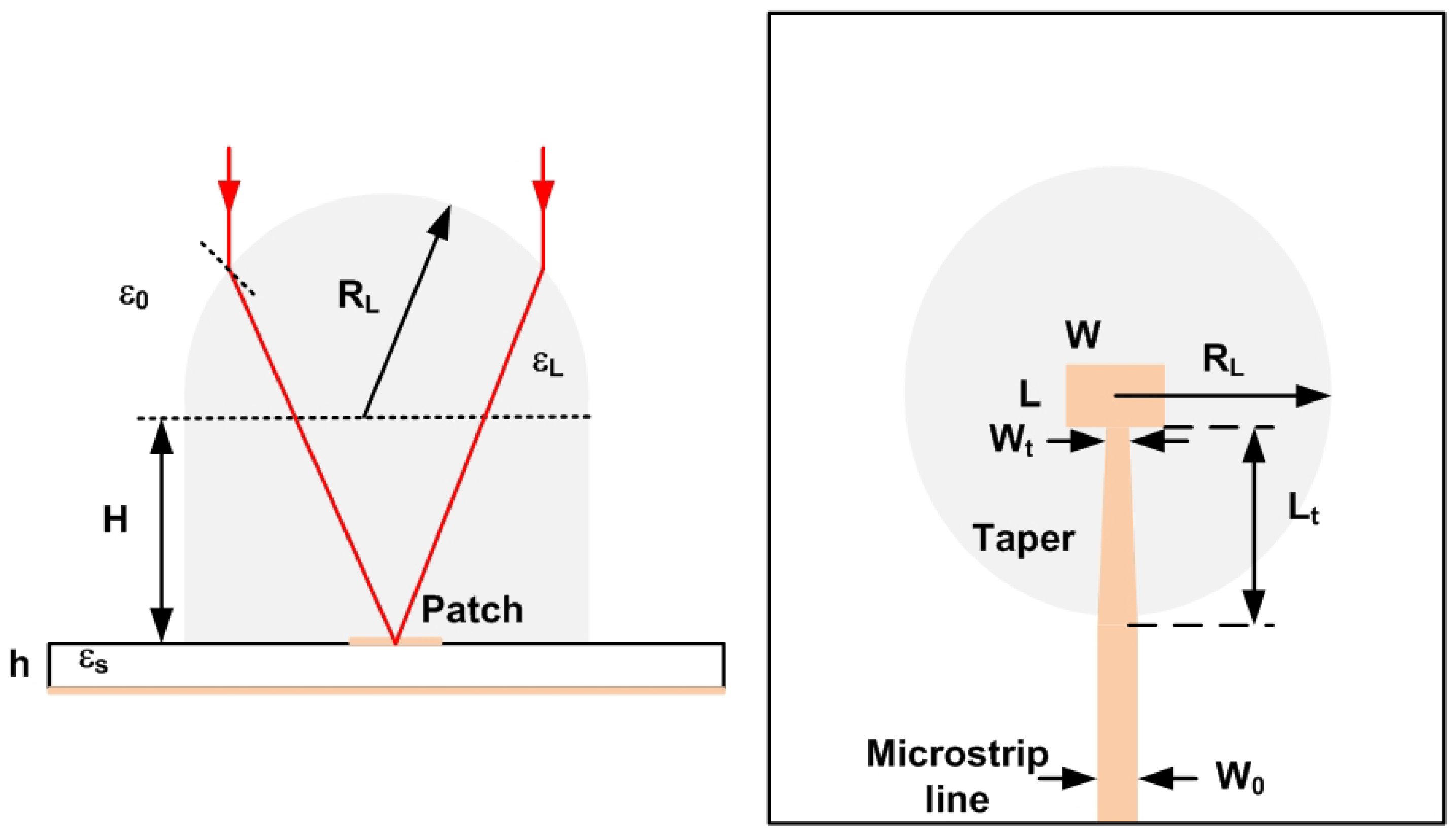
| Dimension | Value (mm) |
|---|---|
| 13.95 | |
| H | 13.4 |
| L | 2.9 |
| W | 3.45 |
| 0.5 | |
| 12.5 |
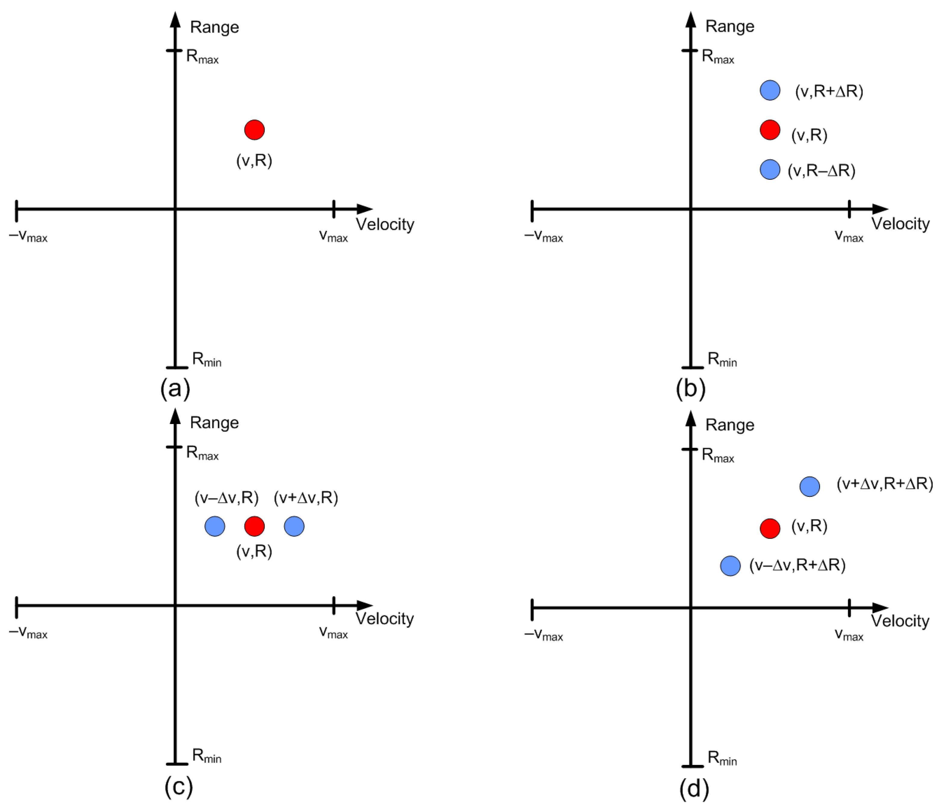
| Case | Modulation Frequency (Hz) | (m) | (m/s) |
|---|---|---|---|
| a | 46,875 | 5 | 0 |
| b | 1000 | 0 | 6.25 |
| c | 46,875 − 1000 | 5 | 6.25 |
| d | 46,875 + 1000 | 5 | −6.25 |
| Parameter | Value |
|---|---|
| Start Frequency | 24 GHz |
| Sweep bandwidth | 300 MHz |
| Sweep slope | 300/250 MHz/s |
| Sweep time | 250 s |
| Sampling frequency | 1.2 Mbps |
| Number of samples per chirp | 256 |
| Number of chirps per frame | 128 |
| Transmit antennas | 2 |
| Receive antennas | 4 |
Publisher’s Note: MDPI stays neutral with regard to jurisdictional claims in published maps and institutional affiliations. |
© 2022 by the authors. Licensee MDPI, Basel, Switzerland. This article is an open access article distributed under the terms and conditions of the Creative Commons Attribution (CC BY) license (https://creativecommons.org/licenses/by/4.0/).
Share and Cite
Lazaro, A.; Porcel, A.; Lazaro, M.; Villarino, R.; Girbau, D. Spoofing Attacks on FMCW Radars with Low-Cost Backscatter Tags. Sensors 2022, 22, 2145. https://doi.org/10.3390/s22062145
Lazaro A, Porcel A, Lazaro M, Villarino R, Girbau D. Spoofing Attacks on FMCW Radars with Low-Cost Backscatter Tags. Sensors. 2022; 22(6):2145. https://doi.org/10.3390/s22062145
Chicago/Turabian StyleLazaro, Antonio, Arnau Porcel, Marc Lazaro, Ramon Villarino, and David Girbau. 2022. "Spoofing Attacks on FMCW Radars with Low-Cost Backscatter Tags" Sensors 22, no. 6: 2145. https://doi.org/10.3390/s22062145
APA StyleLazaro, A., Porcel, A., Lazaro, M., Villarino, R., & Girbau, D. (2022). Spoofing Attacks on FMCW Radars with Low-Cost Backscatter Tags. Sensors, 22(6), 2145. https://doi.org/10.3390/s22062145