
Compact Wideband Double-Slot Microstrip Feed Engraved TEM Horn Strip Antennas on a Multilayer Substrate Board for in Bed Resting Body Positions Determination Based on Artificial Intelligence


Abstract
1. Introduction
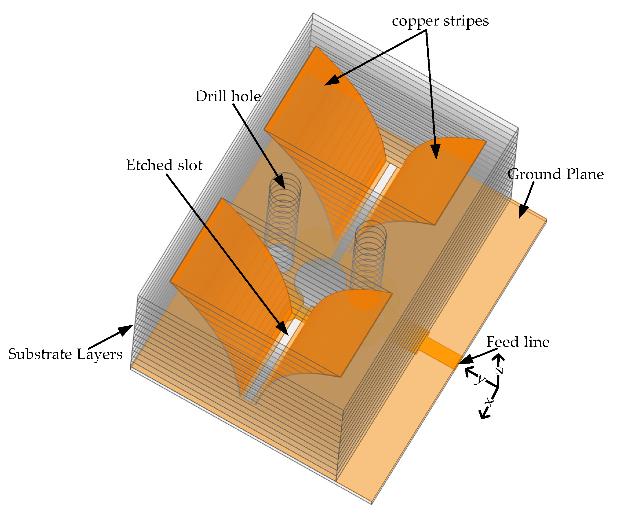
2. Antenna Design
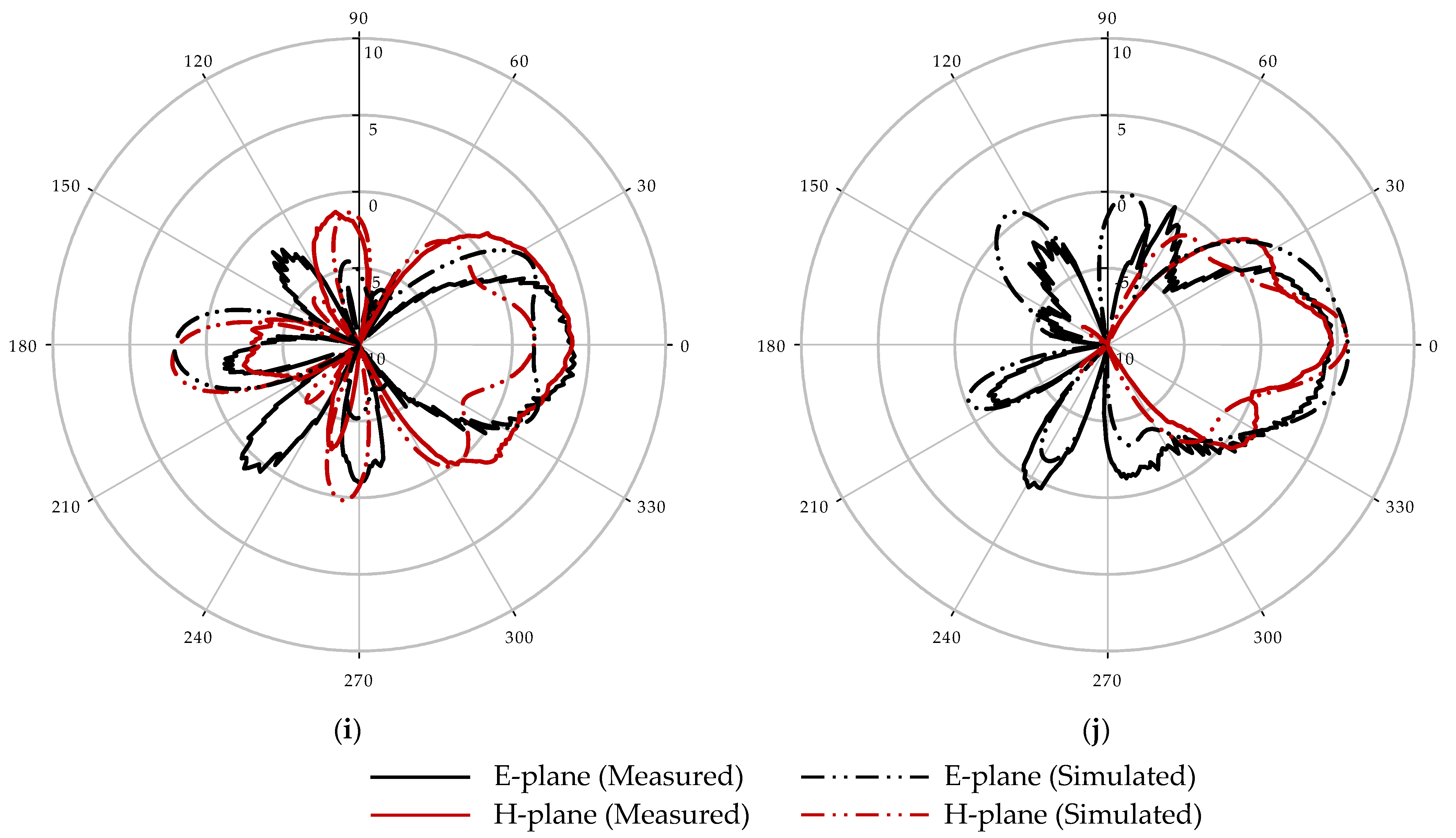
3. Result and Discussion
4. Experimental Study and Results
4.1. Experimental Setup
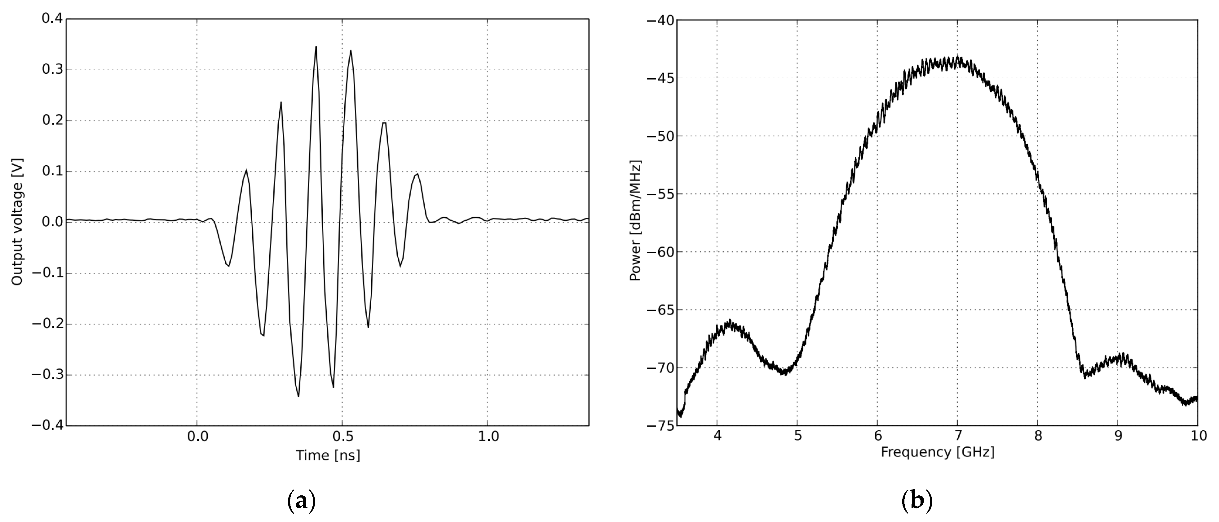
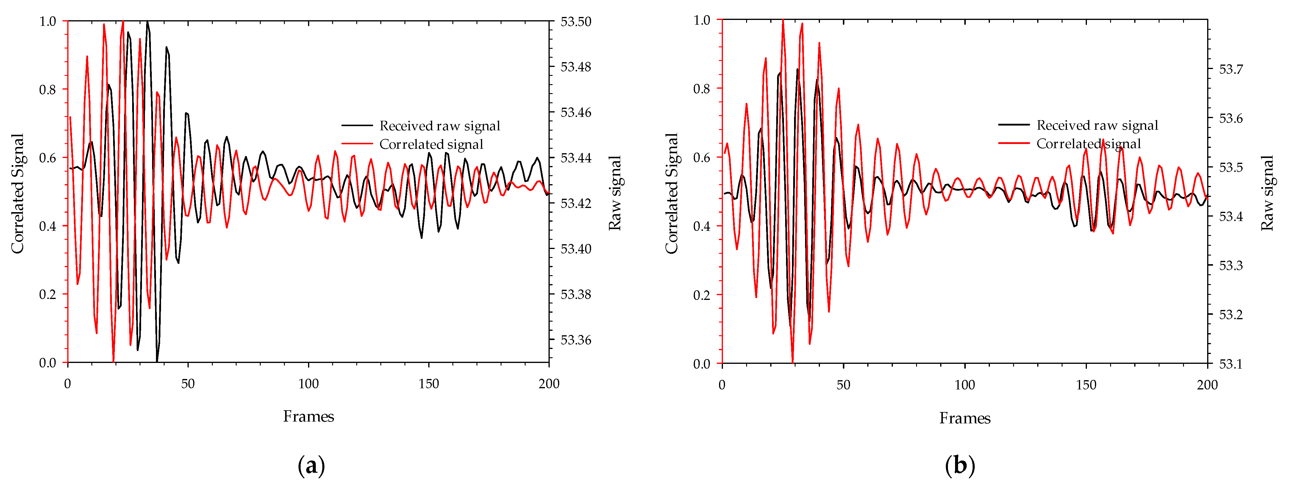
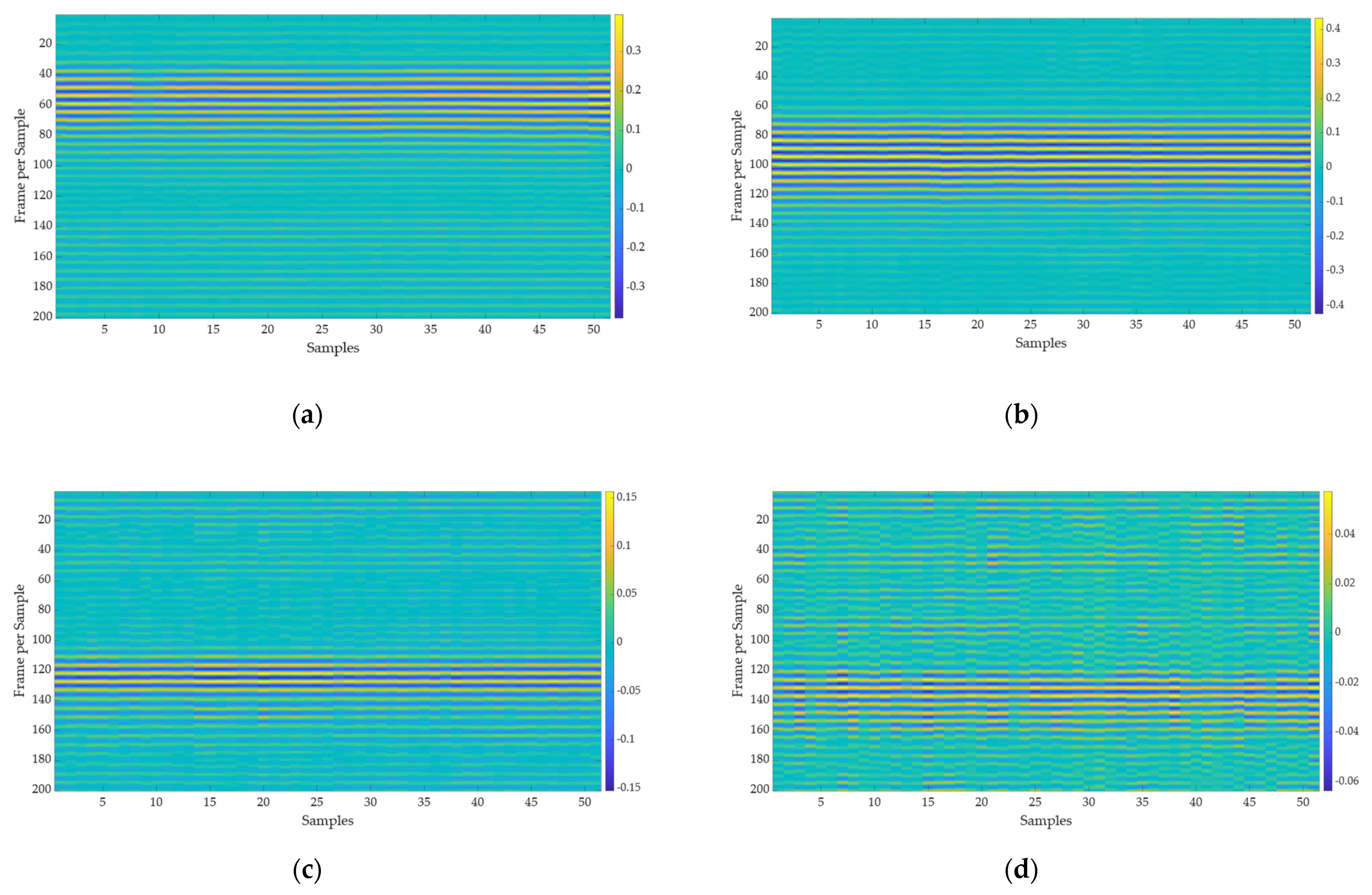
4.2. Signal Analysis
4.3. Position Results Using Standard Recurrent Neural Network (RNN)
4.4. Comparison with RNN Techniques
5. Conclusions
Author Contributions
Funding
Institutional Review Board Statement
Informed Consent Statement
Data Availability Statement
Conflicts of Interest
References
- Chung, K.-H.; Pyun, S.-H.; Chung, S.-Y.; Choi, J.-H. Design of a wideband TEM horn antenna. In Proceedings of the IEEE Antennas and Propagation Society International Symposium. Digest. Held in Conjunction with: USNC/CNC/URSI North American Radio Sci. Meeting (Cat. No.03CH37450), Columbus, OH, USA, 22–27 June 2003. [Google Scholar]
- Chen, G.-Y.; Sun, J.-S.; Huang, S.-Y.; Huang, C.-J.; Wu, K.-L.; Chen, Y.D.; Lin, C.-H. The Tapered TEM Horn Antenna Design for EMC and Radiation Measurement. In Proceedings of the 2006 7th International Symposium on Antennas, Propagation & EM Theory, Guilin, China, 26–29 October 2006. [Google Scholar]
- Fedorov, V.M.; Efanov, M.V.; Ostashev, V.Y.; Tarakanov, V.P.; Ul’Yanov, A.V. Antenna Array with TEM-Horn for Radiation of High-Power Ultra Short Electromagnetic Pulses. Electronics 2021, 10, 1011. [Google Scholar] [CrossRef]
- Harima, K.; Kubo, T.; Ishida, T. Evaluation of a TEM horn antenna for radiated immunity tests in close proximity. IEICE Commun. Express 2020, 9, 60–65. [Google Scholar] [CrossRef]
- Jezova, J.; Lambot, S.; Fedeli, A.; Randazzo, A. Ground-penetrating radar for tree trunk investigation. In Proceedings of the 2017 9th International Workshop on Advanced Ground Penetrating Radar (IWAGPR), Edinburgh, UK, 28–30 June 2017. [Google Scholar]
- Miralles, E.; Schoenlinner, B.; Belenguer, Á.; Esteban, H.; Ziegler, V. A 3-D printed PCB integrated TEM horn antenna. Radio Sci. 2019, 54, 158–165. [Google Scholar] [CrossRef]
- Ashraf, N.; Kishk, A.A.; Sebak, A.-R. Slot-Excited Wideband Horn Antenna with Microstrip Line Feeding for Ka-Band Applications. In Proceedings of the 2019 IEEE International Symposium on Antennas and Propagation and USNC-URSI Radio Science Meeting, Atlanta, GA, USA, 7–12 July 2019. [Google Scholar]
- Rahimi, E.; Neshati, M.H. Low profile modified H-plane SIW horn antenna with improved directivity. In Proceedings of the 2014 Third Conference on Millimeter-Wave and Terahertz Technologies (MMWATT), Tehran, Iran, 30 December 2014–1 January 2015. [Google Scholar]
- Shao, J.; Fang, G.; Fan, J.; Ji, Y.; Yin, H. TEM Horn Antenna Loaded With Absorbing Material for GPR Applications. IEEE Antennas Wirel. Propag. Lett. 2014, 13, 523–527. [Google Scholar] [CrossRef]
- Lee, R.Q.; Lee, K.F.; Bobinchak, J. Two-layer electromagnetically coupled rectangular patch antenna. In Proceedings of the 1988 IEEE AP-S. International Symposium, Antennas and Propagation, Syracuse, NY, USA, 6–10 June 1988. [Google Scholar]
- Tsao, C.H.; Hwang, Y.M.; Kilburg, F.; Dietrich, F. Aperture-coupled patch antennas with wide-bandwidth and dual-polarization capabilities. In Proceedings of the 1988 IEEE AP-S. International Symposium, Antennas and Propagation, Syracuse, NY, USA, 6–10 June 1988. [Google Scholar]
- Luo, Y.; Bornemann, J. Substrate Integrated Waveguide Horn Antenna on Thin Substrate with Back-Lobe Suppression and Its Application to Arrays. IEEE Antennas Wirel. Propag. Lett. 2017, 16, 2622–2625. [Google Scholar] [CrossRef]
- Ghassemi, N.; Wu, K. Millimeter-Wave Integrated Pyramidal Horn Antenna Made of Multilayer Printed Circuit Board (PCB) Process. IEEE Trans. Antennas Propag. 2012, 60, 4432–4435. [Google Scholar] [CrossRef]
- Diao, Y.; Rashed, E.A.; Hirata, A. Large-Scale Analysis of the Head Proximity Effects on Antenna Performance Using Machine Learning Based Models. IEEE Access 2020, 8, 154060–154071. [Google Scholar] [CrossRef]
- Sharma, M.K.; Kumar, M.; Saini, J.P.; Gangwar, D.; Kanaujia, B.K.; Singh, S.P.; Ekuakille, A.L. Experimental Investigation of the Breast Phantom for Tumor Detection Using Ultra-Wide Band–MIMO Antenna Sensor (UMAS) Probe. IEEE Sens. J. 2020, 20, 6745–6752. [Google Scholar] [CrossRef]
- Martins, R.A.; Felicio, J.M.; Costa, J.R.; Fernandes, C.A. Comparison of Slot-based and Vivaldi Antennas for Breast Tumor Detection using Machine Learning and Microwave Imaging Algorithms. In Proceedings of the 2021 15th European Conference on Antennas and Propagation (Eucap), Düsseldorf, Germany, 22–26 March 2021. [Google Scholar]
- Campbell, M.A.; Okoniewski, M.; Fear, E.C. TEM horn antenna for near-field microwave imaging. Microw. Opt. Technol. Lett. 2010, 52, 1164–1170. [Google Scholar] [CrossRef]
- Latif, S.I.; Tapia, D.F.; Herrera, D.R.; Nepote, M.S.; Pistorius, S.; Shafai, L. A Directional Antenna in a Matching Liquid for Microwave Radar Imaging. Int. J. Antennas Propag. 2015, 2015, 751739. [Google Scholar] [CrossRef]
- Mallahzadeh, A.R.; Karshenas, F. Modified Tem Horn Antenna for Broadband Applications. Prog. Electromagn. Res. 2009, 90, 105–119. [Google Scholar] [CrossRef][Green Version]
- Lee, S.; Yang, Y.; Lee, K.-Y.; Jung, K.-Y.; Hwang, K. Robust Design of 3D-Printed 6–18 GHz Double-Ridged TEM Horn Antenna. Appl. Sci. 2018, 8, 1582. [Google Scholar] [CrossRef]
- Du, H.; Yu, X.; Zhang, H.; Chen, P. Design of broadband and dual-polarized dielectric-filled pyramidal horn antenna based on substrate-integrated waveguide. Microw. Opt. Technol. Lett. 2019, 61, 702–708. [Google Scholar] [CrossRef]
- Zhu, Y.; Dang, W.; Liu, X.; Chen, Y.; Zhou, X.; Lu, H. Generation of plane spiral orbital angular momentum using circular double-slot Vivaldi antenna array. Sci. Rep. 2020, 10, 18328. [Google Scholar] [CrossRef] [PubMed]
- Kim, S.W.; Choi, D.Y. Analysis of Beamforming Antenna for Practical Indoor Location-Tracking Application. Sensors 2019, 19, 3040. [Google Scholar] [CrossRef] [PubMed]
- XETHRU by NOVELDA. X2 Impulse Radar Transceiver; NOVELDA: Oslo, Norway, 2015. [Google Scholar]
- Ghimire, J.; Choi, D.-Y. Ultra-Wide Band Double-Slot Podal and Antipodal Vivaldi Antennas Feed by Compact Out-of-Phase Power Divider Slot for Fluid Properties Determination. Sensors 2022, 22, 4543. [Google Scholar] [CrossRef]
- Ghimire, J.; Diba, F.D.; Kim, J.-H.; Choi, D.-Y. Vivaldi Antenna Arrays Feed by Frequency-Independent Phase Shifter for High Directivity and Gain Used in Microwave Sensing and Communication Applications. Sensors 2021, 21, 6091. [Google Scholar] [CrossRef]


| Parameter | mm | Parameter | mm |
|---|---|---|---|
| λg | 19 | Fl1 | 4 |
| Ls | 6 (λg/5) + Fl1 | Fl2 | λg/4 |
| Ws | 2 (Sr + Fw + Cw) + λg/4 | Wl2 | 2.63 |
| Hs1 | 0.8 | Fr | 2 |
| Hs2 | 1.6 | Sr | 2.5 |
| Ths | 13 (Hs2) | Dr | 1.5 |
| Fw | 1.54 | Cbw | Sw + 1 |
| Cl | 19 | Sw | 0.8 |
| Cw | (λg + Sw)/2 | --- | --- |
| Ref. | Frequency Range (GHz) | Feed System | Size (mm2) | Gain (dBi) |
|---|---|---|---|---|
| [17] | 2–12 | A microstrip-to-parallel strip balun | 63.2 × 60.4 × 80 | -- |
| [18] | 1.54–5.29 | Co-axial cable | 61.6 × 61.6 × 108 | 7.8 |
| [19] | 2–14 | Co-axial cable | 74 × 74 × 80 | 11.52 |
| [20] | 6–18 | Adaptor based on double-ridged waveguide | 29.58 × 22.97 × 36.1 | 10.75 |
| [21] | 12.25–12.75 and 14.0–14.5 | Substrate-integrated coaxial line | 26 × 26 × 26.3 | 7.7 and 9.2 |
| [22] | 4–6 | 1 × 8 tapered arc strip impedance transformer lines | 54.4 × 54.4 × 85.7 | 5.7 |
| [23] | 1.45–5.78 | 4 × 4 butler matrix | 70.65 × 90 × 140 | 9.18 |
| Proposed antenna | 5.6–15.6 | T-junction power divider with slot to radiating plane transition | 26.8 × 32.63 × 21.6 | 9.46 |
| RNN Layers | Validation Accuracy |
|---|---|
| LSTM | 97.6 |
| GRU | 98.38 |
| BiLSTM | 99.19 |
Publisher’s Note: MDPI stays neutral with regard to jurisdictional claims in published maps and institutional affiliations. |
© 2022 by the authors. Licensee MDPI, Basel, Switzerland. This article is an open access article distributed under the terms and conditions of the Creative Commons Attribution (CC BY) license (https://creativecommons.org/licenses/by/4.0/).
Share and Cite
Ghimire, J.; Kim, J.-H.; Choi, D.-Y. Compact Wideband Double-Slot Microstrip Feed Engraved TEM Horn Strip Antennas on a Multilayer Substrate Board for in Bed Resting Body Positions Determination Based on Artificial Intelligence. Sensors 2022, 22, 9555. https://doi.org/10.3390/s22239555
Ghimire J, Kim J-H, Choi D-Y. Compact Wideband Double-Slot Microstrip Feed Engraved TEM Horn Strip Antennas on a Multilayer Substrate Board for in Bed Resting Body Positions Determination Based on Artificial Intelligence. Sensors. 2022; 22(23):9555. https://doi.org/10.3390/s22239555
Chicago/Turabian StyleGhimire, Jiwan, Ji-Hoon Kim, and Dong-You Choi. 2022. "Compact Wideband Double-Slot Microstrip Feed Engraved TEM Horn Strip Antennas on a Multilayer Substrate Board for in Bed Resting Body Positions Determination Based on Artificial Intelligence" Sensors 22, no. 23: 9555. https://doi.org/10.3390/s22239555
APA StyleGhimire, J., Kim, J.-H., & Choi, D.-Y. (2022). Compact Wideband Double-Slot Microstrip Feed Engraved TEM Horn Strip Antennas on a Multilayer Substrate Board for in Bed Resting Body Positions Determination Based on Artificial Intelligence. Sensors, 22(23), 9555. https://doi.org/10.3390/s22239555