

SF-Partition-Based Clustering and Relaying Scheme for Resolving Near–Far Unfairness in IoT Multihop LoRa Networks


Abstract
1. Introduction
1.1. Background and Motivation
1.2. Contribution
- We provide an SF-based network partitioning method to determine the best partitioning threshold point for dividing SF zones of an IoT LoRa network into the LSFZ and the HSFZ. To bridge the performance gap among the SF zones, an optimal SF division method based on a heuristic algorithm is proposed.
- We provide a density-based subspace clustering method for grouping adjacent LDs in the HSFZ. To construct clusters of arbitrary shape and to select CHs by a binary score representation, a combination of the DBSCAN algorithm and naive Bayes classifier is proposed.
- We provide the relay LD selecting method to ideally choose the best relay LD only in the LSFZ for extending transmissions of CHs in the HSFZ to the GW by multihop communications. The harmonic mean based on the packet success probability and the remaining energy is proposed to choose the best one among all candidate relay LDs.
- We maximize the performance of packet success probability, scalability, and fairness in the SF zones of an IoT LoRa network. To ensure the optimal zone allocation with connection fairness, the packet success probability of each LD in a certain SF zone is examined.
- We conduct simulations in various environments for evaluating the performance of the proposed SFPCR scheme. Simulation results demonstrate that the proposed SFPCR scheme raises the packet success probability by bridging the packet delivery success probability gap between SF zones while conserving more energy among LDs by reducing the number of packets compared with existing schemes.
1.3. Organisation
2. Related Works
2.1. Spread Factor Allocation in LoRa Networks
2.2. Clustering in LoRa Networks
2.3. Multihop Communication in LoRa Networks
3. System Model
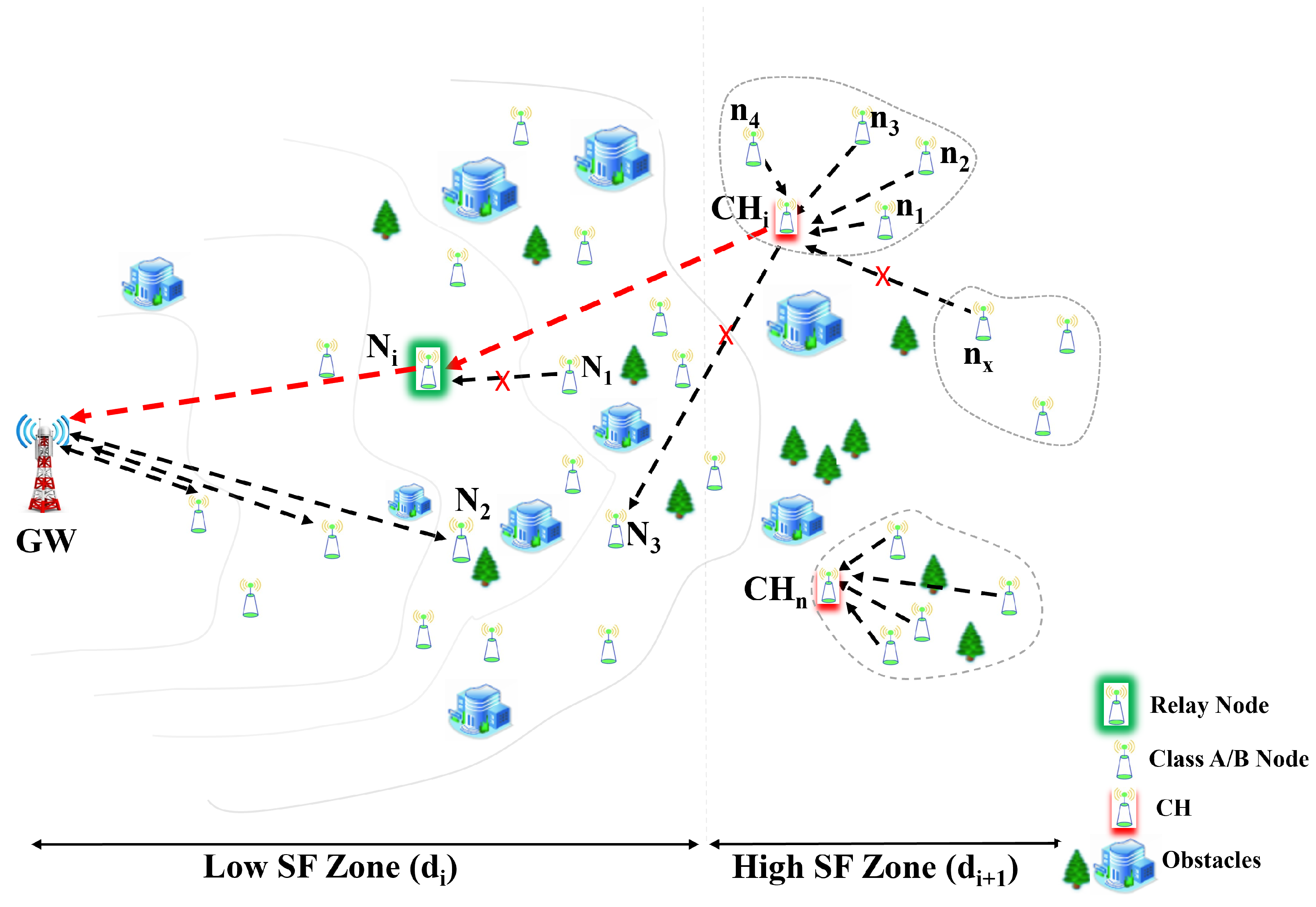
3.1. Network Model
3.2. Energy Model
3.3. Success Probability Model
4. SF-Partition-Based Clustering and Relaying (SFPCR) Scheme
4.1. SF-Based IoT Network Partitioning
| Algorithm 1: Pseudocode for boundary cut-off point of LSFZ and HSFZ. |
Input:: LoRa device success probability Input:N: number of IoT LoRa devices Input:x: LoRa device’s location Input: BW: bandwidth Input: SF: spreading factor of a LoRa device Output: Boundary point LSFZ and HSFZ,
|
4.2. Density-Based Subspace Clustering in the HSFZ
- Initial setup phase: During this phase, the GW applies global knowledge from all the LoRa devices to build density-based subspace clusters based on the LoRa devices’ distribution and information. The SFPCR scheme generates density-based subspace clusters of LoRa devices whose neighbourhood contains a minimum number of other devices within a given radius (). In this case, is calculated using the k-nearest neighbour to its immediate neighbours [49]. Meanwhile, given the value k is represented as , we chose 4 as the k value, and the 4-nearest distance from was the Euclidean distance from to its 4-nearest neighbours, independent of the transmission range.Without loss of generality, three types of LoRa devices were defined: core LoRa devices, which contained at least LoRa devices [50] in their neighbourhood. Border LoRa devices did not have enough devices in their neighbourhood, but they were close to some core LoRa devices. Finally, other devices were considered outliers.Assuming a set of LoRa devices in the HSFZ made up of subspaces , let be the set of LoRa devices belonging to subspace and . Starting with an arbitrary LoRa device , the method returned all LoRa devices that were density-reachable from using and . As illustrated in Figure 3a, LoRa device is directly density-reachable from LoRa device if is a core LoRa device and is in its neighbourhood. A LoRa device is defined as density-reachable from a core LoRa device if there exists a chain of devices from to , with each device being directly density-reachable from the prior LD. However, if is a border device, no devices are density-reachable from and then the algorithm visits the next LoRa device.To deduce the parameter , we first computed the Euclidean distances with Equation (16) of all the -nearest neighbours from Equation (17), and selected the maximum 4th -nearest neighbour distance as shown in the Equation (18).where is the Euclidean distance from the core LD to device .In this case, is the number of neighbours within an arbitrary subspace cluster distance (), and is the minimum number of LoRa devices to make a local subcluster, respectively.for , where represents ’s nearest neighbours such that the number of LoRa devices in is equivalent to k. As a result, the algorithm merges all the local subclusters to form the arbitrary density-based subspace cluster based on () as shown in Figure 3b. However, if (), no cluster is formed. A density connection can also refer to the relationship that exists between border LDs that are part of the same cluster but do not have a core LD in common with which they share any density reachability. A local subcluster is formed by a core LD and all of its retrieved nearby LDs within a predefined distance, and it expands using the two fundamental concepts of density-reachable and density-connected, as long as the conditions are met [51]:
- -
- is a member of a cluster if is a member of and is density-reachable from .
- -
- and are density-connected if both of them are members of a cluster .
Assume the distance in the HSFZ between two sets and of LDs is defined as . Two sets with at least the density of the thinnest cluster will be separated only if the distance between them is greater than . The LoRa device density connection determines the maximum number of LDs in an arbitrary cluster. Furthermore, in the steady-state phase, the GW is critical in computing the CHs of clusters by using network information from the IoT LoRa devices during network initialization. - Steady-state phase: In this phase, the cluster head selection is performed using a naive Bayes classifier [48]. The GW plays a crucial role in generating the score value needed to categorize normal LoRa devices as CHs or cluster members. Based on the Bayes classifier, the GW determines the best LoRa devices to become CHs based on their binary score. The value of indicates the appropriate number of CHs. In [52], the authors explained what clustering algorithms were and how they worked. Moreover, there were three types of algorithms for choosing CHs: predetermined, random, and attribute-based. In the SFPCR scheme, we adopted attribute-based algorithms to select CHs. The GW constitutes the vector metric attributes for a LoRa device LD(i) to become the CH. = , where j is the vector’s dimension. The attributes of an LD(i) include, but are not limited to, the residual energy (), the link quality () between LD(i) and its neighbour, and the distance ratio evaluated as the minimum distance of a source node to the relay LoRa device in the LSFZ. As a result, a vector of attributes can be expressed as Equation (19).Here, (24) and (13) are considered as the primary parameters, and is considered as the secondary parameter and is calculated using Equation (20).In Equation (20), is the source LD in the ith cluster, is the selected relay LD at a time (t), and is the distance from the source LD to the relay LD, respectively. Then, the goal of the CH selection is to find an appropriate mapping relationship between C and , where C is the binary score of attributes to which the LD belongs, either a cluster member (CM) or a cluster head (CH), and is expressed as .expresses the probability of LD(i) becoming the CH with the classification using the Bayesian theorem expressed in Equation (21). Finally, the GW selects the LoRa device with the highest probability of becoming a CH within the clustered region based on Equation (22), which is also represented in Algorithm 2.
| Algorithm 2: Pseudocode to select cluster heads in the HSFZ. |
Input:: set of LoRa Devices (LDs) Input:: LoRa Device metric attributes Input: N: number of LoRa Devices Input:: optimal number of CHs Output: Clusters of all LDs in HSFZ, CH allocation
|
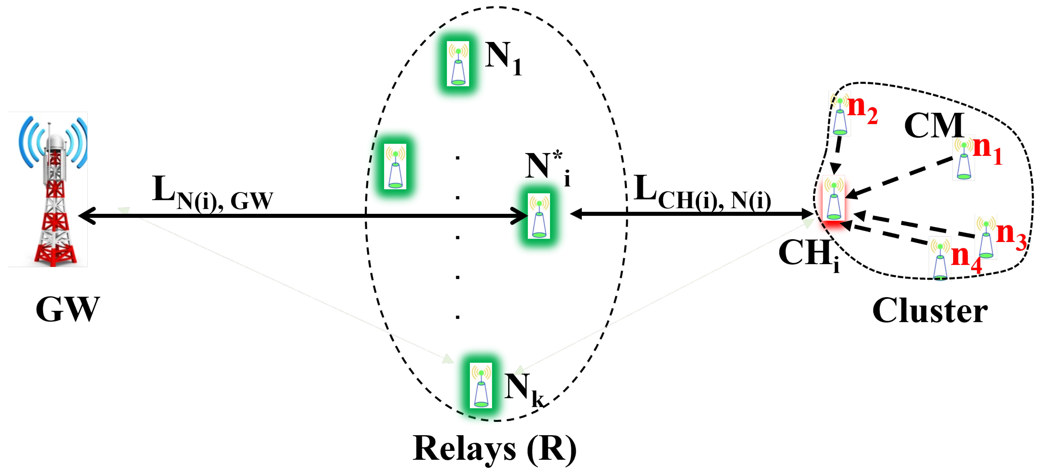
4.3. Relay LoRa Device Selection in the LSFZ
5. Performance Evaluation
5.1. Simulation Environments and Scenario
5.2. Performance Evaluation Metrics
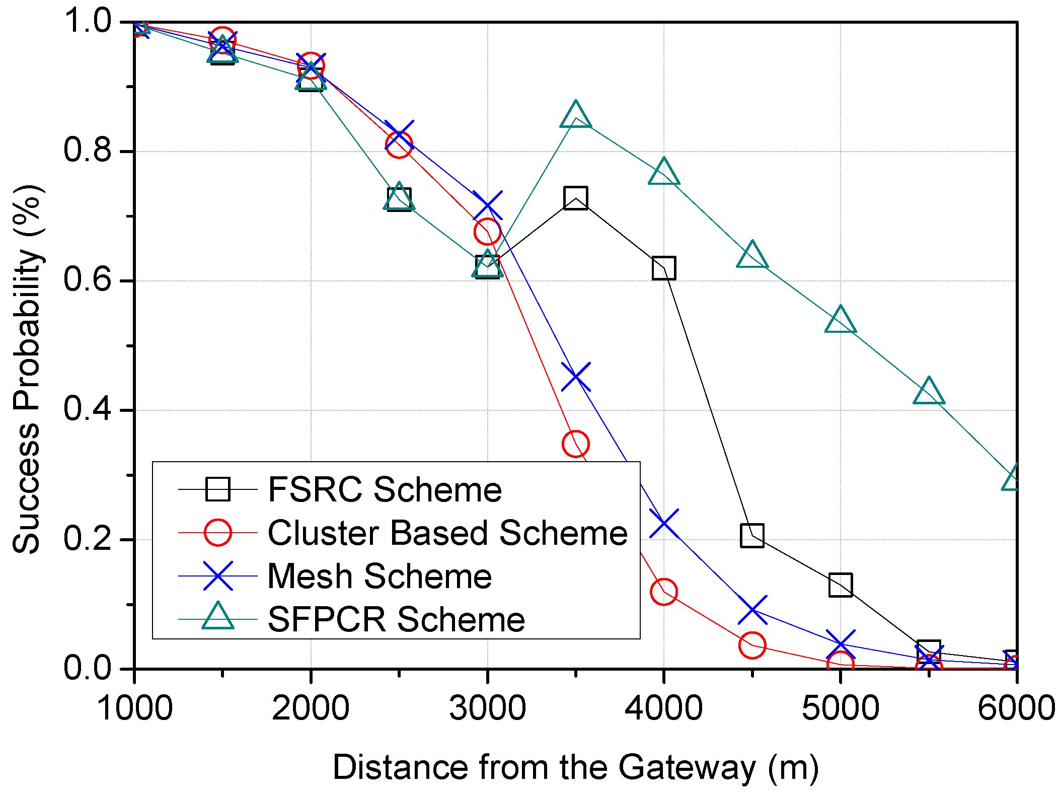
- Packet success probabilityA frame transmission is considered successful when no collisions occur and all the bits in the frame are accurately decoded despite interference [54]. The harsh environment and capture effects are two factors that can have an impact on the success of data transmissions between LDs and GWs. It is critical to consider both the likelihood of the GW receiving an uplink from the source LD and the likelihood of the device successfully receiving a downlink.
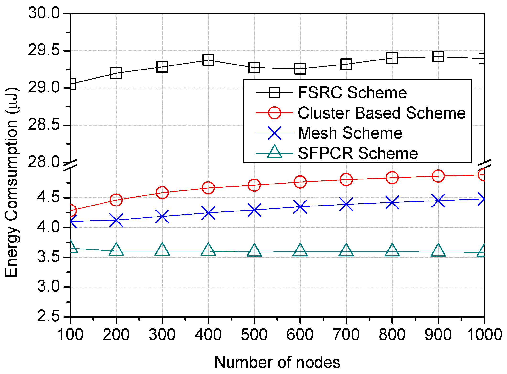
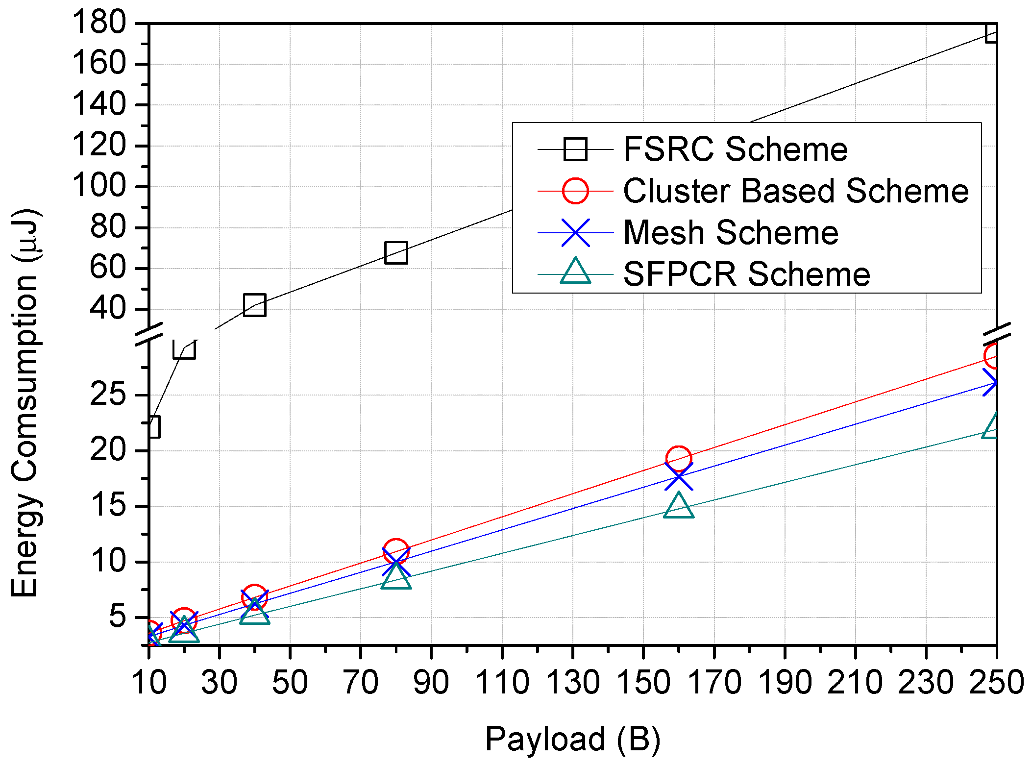
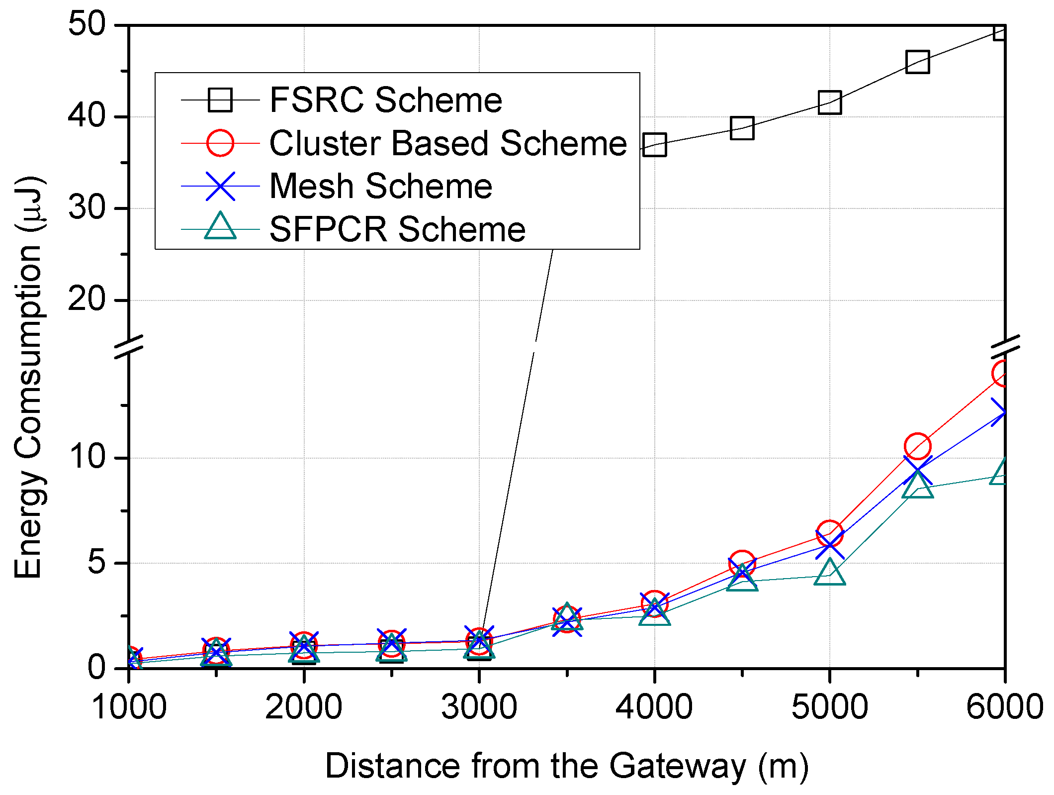
- Energy consumptionWe considered the energy consumption among LoRa devices, which refers to the number of delivered data bits per unit of energy consumed by a LoRa device [39]. The SFPCR scheme aimed to balance the HSFZ’s energy efficiency by shortening the ToA of the LDs.
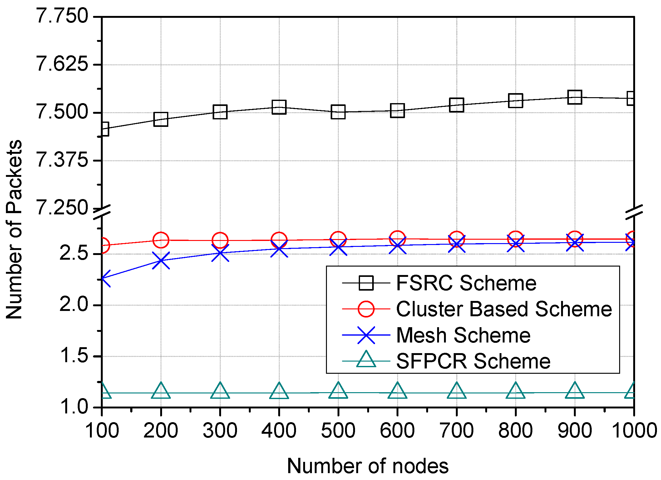
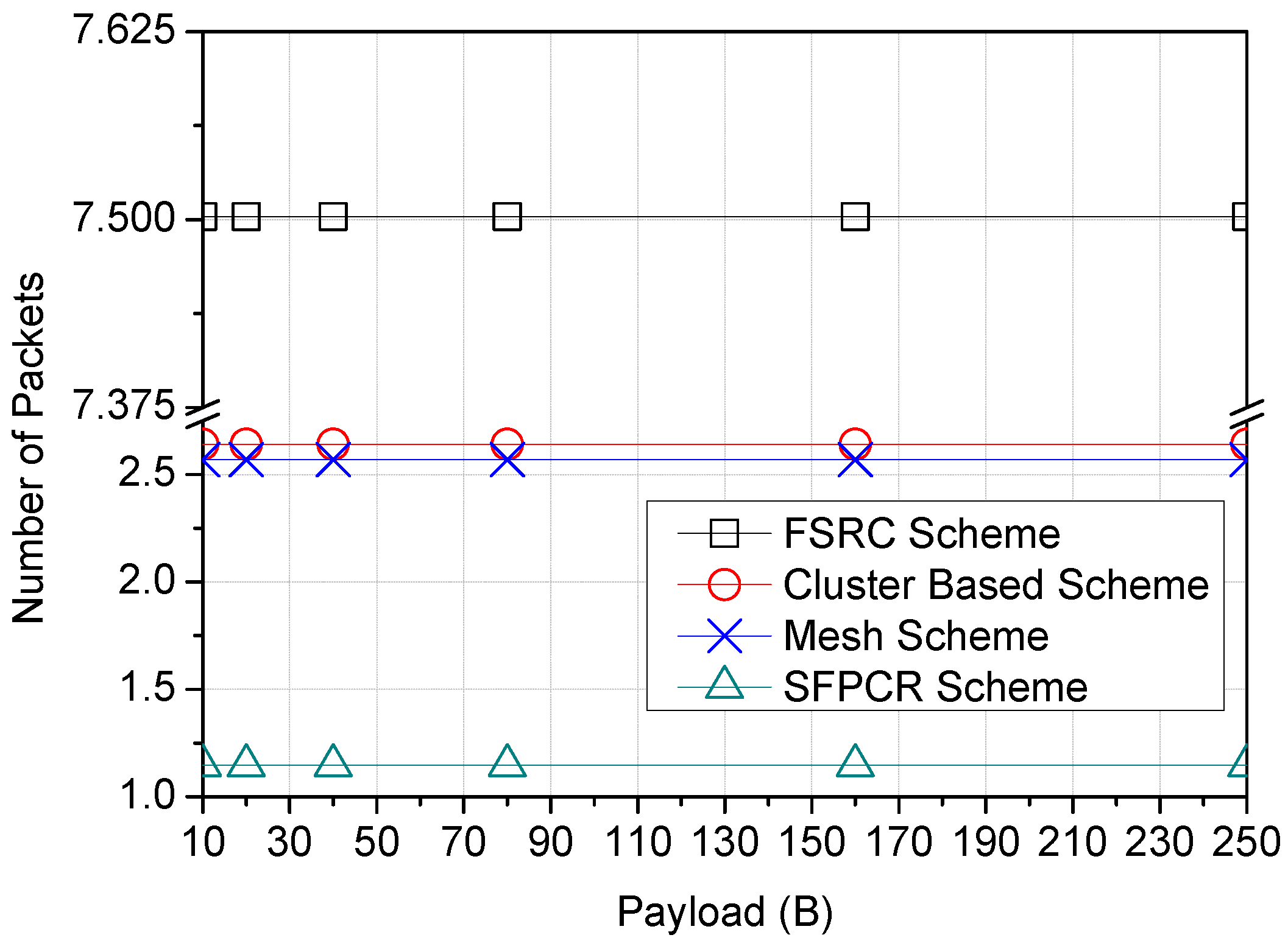
- Number of PacketsWhen analysing traffic behaviour in a LoRa network, the number of packets passing through the network to the GW is critical. In the LoRaWAN network, packets are sent infrequently and are affected by a variety of factors. As a result, the primary objective here was to ensure an effective transmission that limited duplicate packets, collisions, and retransmissions, all of which produce large quantities of network congestion and thus impede overall network performance.
5.3. Simulation Results
6. Conclusions and Discussion
Author Contributions
Funding
Institutional Review Board Statement
Informed Consent Statement
Data Availability Statement
Conflicts of Interest
Nomenclature
| Symbol | Description |
| LD(i) | LoRa device i |
| CH | Cluster head |
| Number of symbols in a packet preamble | |
| Number of symbols in a payload | |
| Size of the transmitted packet | |
| Density of LDs in a particular SF | |
| Density of LoRa devices | |
| Virtual partition threshold point | |
| Bit rate | |
| LDs metric attribute | |
| Time on air for single transmission of LD(i) | |
| Time for transmitting a symbol | |
| Interferers in SF region | |
| Optimal partition point | |
| Success probability | |
| Average success probability | |
| Link quality | |
| Energy dissipated in light-sleep mode | |
| Energy consumption | |
| Total amount of consumed energy | |
| Residual energy of a LoRa node | |
| Maximum number of LoRa devices | |
| Minimum number of LoRa devices | |
| Combined relay parameters with weights | |
| Optimal rank | |
| Euclidean distance | |
| Minimum distance ratio between nodes | |
| Probability of LD(i) becoming the CH |
References
- Deese, A.S.; Jesson, J.; Brennan, T.; Hollain, S.; Stefanacci, P.; Driscoll, E.; Dick, C.; Garcia, K.; Mosher, R.; Rentsch, B.; et al. Long-Term Monitoring of Smart City Assets via Internet of Things and Low-Power Wide-Area Networks. IEEE Internet Things J. 2021, 8, 222–231. [Google Scholar] [CrossRef]
- Barnett, T.; Jain, S.; Andra, U.; Khurana, T. Cisco Visual Networking Index (VNI) Complete Forecast Update, 2017–2022. Presentation 2018, 1–30. Available online: https://s3.amazonaws.com/media.mediapost.com/uploads/CiscoForecast.pdf (accessed on 5 September 2022).
- Mekki, K.; Bajic, E.; Chaxel, F.; Meyer, F. A comparative study of LPWAN technologies for large-scale IoT deployment. ICT Express 2019, 5, 1–7. [Google Scholar] [CrossRef]
- LoRa Alliance. LoRaWAN 1.1 Specification; LoRa Alliance: Beaverton, OR, USA, 2017; Volume 11. [Google Scholar]
- Reynders, B.; Meert, W.; Pollin, S. Range and coexistence analysis of long range unlicensed communication. In Proceedings of the 23rd International Conference on Telecommunications (ICT), Thessaloniki, Greece, 16–18 May 2016; pp. 1–6. [Google Scholar] [CrossRef]
- Georgiou, O.; Raza, U. Low Power Wide Area Network Analysis: Can LoRa Scale? IEEE Wirel. Commun. Lett. 2017, 6, 162–165. [Google Scholar] [CrossRef]
- Wang, X.; Kong, L.; He, L.; Chen, G. mLoRa: A Multi-Packet Reception Protocol in LoRa networks. In Proceedings of the 2019 IEEE 27th International Conference on Network Protocols (ICNP), Chicago, IL, USA, 8–10 October 2019; pp. 1–11. [Google Scholar] [CrossRef]
- Centelles, R.P.; Freitag, F.; Meseguer, R.; Navarro, L. Beyond the Star of Stars: An Introduction to Multihop and Mesh for LoRa and LoRaWAN. IEEE Pervasive Comput. 2021, 20, 63–72. [Google Scholar] [CrossRef]
- Yuan, L.; Wu, T.; Zhou, A. Performance Research of ALOHA Protocol. In Proceedings of the 7th International Conference on Cyber Security and Information Engineering, Brisbane, Australia, 3–25 September 2022. [Google Scholar]
- Adelantado, F.; Vilajosana, X.; Tuset-Peiro, P.; Martinez, B.; Melia-Segui, J.; Watteyne, T. Understanding the Limits of LoRaWAN. IEEE Commun. Mag. 2017, 55, 34–40. [Google Scholar] [CrossRef]
- Phung, K.H.; Tran, H.; Nguyen, Q.; Huong, T.T.; Nguyen, T.L. Analysis and assessment of LoRaWAN. In Proceedings of the 2018 2nd International Conference on Recent Advances in Signal Processing, Telecommunications & Computing (SigTelCom), Ho Chi Minh, Vietnam, 29–31 January 2018. [Google Scholar]
- Lyu, J.; Yu, D.; Fu, L. Achieving Max-Min Throughput in LoRa Networks. In Proceedings of the 2020 International Conference on Computing, Networking and Communications (ICNC), Big Island, HI, USA, 17–20 February 2020; pp. 471–476. [Google Scholar] [CrossRef]
- Sisinni, E.; Ferrari, P.; Carvalho, D.F.; Rinaldi, S.; Marco, P.; Flammini, A.; Depari, A. LoRaWAN Range Extender for Industrial IoT. IEEE Trans. Ind. Inform. 2020, 16, 5607–5616. [Google Scholar] [CrossRef]
- Barrachina-Muñoz, S.; Bellalta, B.; Adame, T.; Bel, A. Multi-hop communication in the uplink for LPWANs. Comput. Netw. 2017, 123, 153–168. [Google Scholar] [CrossRef]
- Borkotoky, S.S.; Schilcher, U.; Bettstetter, C. Cooperative Relaying in LoRa Sensor Networks. In Proceedings of the 2019 IEEE Global Communications Conference (GLOBECOM), Big Island, HI, USA, 9–13 December 2019; pp. 1–5. [Google Scholar] [CrossRef]
- Augustin, A.; Yi, J.; Clausen, T.; Townsley, W.M. A study of LoRa: Long range & low power networks for the internet of things. Sensors 2016, 16, 1466. [Google Scholar]
- Haxhibeqiri, J.; De Poorter, E.; Moerman, I.; Hoebeke, J. A survey of LoRaWAN for IoT: From technology to application. Sensors 2018, 18, 3995. [Google Scholar] [CrossRef]
- Enriko, I.K.A.; Abidin, A.Z.; Noor, A.S. Design and Implementation of LoRaWAN-Based Smart Meter System for Rural Electrification. In Proceedings of the 2021 International Conference on Green Energy, Computing and Sustainable Technology (GECOST), Miri, Malaysia, 7–9 July 2021. [Google Scholar]
- Aslam, M.S.; Khan, A.; Atif, A.; Hassan, S.A.; Mahmood, A.; Qureshi, H.K.; Gidlund, M. Exploring Multi-Hop LoRa for Green Smart Cities. IEEE Netw. 2020, 34, 225–231. [Google Scholar] [CrossRef]
- Fargas, B.C.; Petersen, M.N. GPS-free geolocation using LoRa in low-power WANs. In Proceedings of the 2017 Global Internet of Things Summit (Giots), Geneva, Switzerland, 6–9 June 2017. [Google Scholar]
- Zhu, G.; Liao, C.-H.; Sakdejayont, T.; Lai, I.-W.; Narusue, Y.; Morikawa, H. Improving the Capacity of a Mesh LoRa Network by Spreading-Factor-Based Network Clustering. IEEE Access 2019, 7, 21584–21596. [Google Scholar] [CrossRef]
- Farhad, A.; Kim, D.-H.; Pyun, J.-Y. Scalability of LoRaWAN in an Urban Environment: A Simulation Study. In Proceedings of the 2019 Eleventh International Conference on Ubiquitous and Future Networks (ICUFN), Zagreb, Croatia, 2–5 July 2019; pp. 677–681. [Google Scholar] [CrossRef]
- Farhad, A.; Kim, D.-H.; Sthapit, P.; Pyun, J.-Y. Interference-Aware Spreading Factor Assignment Scheme for the Massive LoRaWAN Network. In Proceedings of the 2019 International Conference on Electronics, Information, and Communication (ICEIC), Auckland, New Zealand, 22–25 January 2019; pp. 1–2. [Google Scholar] [CrossRef]
- Mohammadi, S.; Farahani, G. Scalability Analysis of a LoRa Network Under Inter-SF and Co-SF Interference with Poisson Point Process Model. J. Comput. Secur. 2021, 8, 43–57. [Google Scholar]
- Asad Ullah, M.; Iqbal, J.; Hoeller, A.; Souza, R.D.; Alves, H. K-means spreading factor allocation for large-scale LoRa networks. Sensors 2019, 19, 4723. [Google Scholar] [CrossRef] [PubMed]
- Amichi, L.; Kaneko, M.; Rachkidy, N.E.; Guitton, A. Spreading Factor Allocation Strategy for LoRa Networks Under Imperfect Orthogonality. In Proceedings of the ICC 2019–2019 IEEE International Conference on Communications (ICC), Shanghai, China, 20–24 May 2019; pp. 1–7. [Google Scholar] [CrossRef]
- Reynders, B.; Meert, W.; Pollin, S. Power and spreading factor control in low power wide area networks. In Proceedings of the 2017 IEEE International Conference on Communications (ICC), Paris, France, 21–25 May 2017; pp. 1–6. [Google Scholar] [CrossRef]
- Lim, J.-T.; Han, Y. Spreading Factor Allocation for Massive Connectivity in LoRa Systems. IEEE Commun. Lett. 2018, 22, 800–803. [Google Scholar] [CrossRef]
- Gul, O.M.; Erkmen, A.M. Energy-efficient cluster-based data collection by a UAV with a limited-capacity battery in robotic wireless sensor networks. Sensors 2020, 20, 5865. [Google Scholar] [CrossRef]
- Farooq, M.O. Clustering-Based Layering Approach for Uplink Multi-Hop Communication in LoRa Networks. IEEE Netw. Lett. 2020, 2, 132–135. [Google Scholar] [CrossRef]
- Misic, V.B.; Misic, J.; Khan, M.S.I. Optimum Zoning in RF-Recharged Sensor Networks. In Proceedings of the 2016 IEEE 84th Vehicular Technology Conference (VTC-Fall), Montreal, QC, Canada, 18–21 September 2016; pp. 1–6. [Google Scholar] [CrossRef]
- Bor, M.; Vidler, J.E.; Roedig, U. LoRa for the Internet of Things. In Proceedings of the 2016 International Conference on Embedded Wireless Systems and Networks, Graz, Austria, 15–17 February 2016; pp. 361–366. [Google Scholar]
- Lee, S.; Lee, J.; Park, H.-S.; Choi, J.K. A Novel Fair and Scalable Relay Control Scheme for Internet of Things in LoRa-Based Low-Power Wide-Area Networks. IEEE Internet Things J. 2021, 8, 5985–6001. [Google Scholar] [CrossRef]
- Sisinni, E.; Carvalho, D.F.; Ferrari, P. Emergency Communication in IoT Scenarios by Means of a Transparent LoRaWAN Enhancement. IEEE Internet Things J. 2020, 7, 10684–10694. [Google Scholar] [CrossRef]
- Mugerwa, D.; Nam, Y.; Cho, H.; Choi, H.; Shin, Y.; Lee, E. Implicit Multi-hop Communication Scheme based on Overhearing in IoT LoRa Networks. In Proceedings of the 2022 Thirteenth International Conference on Ubiquitous and Future Networks (ICUFN), Barcelona, Spain, 5–8 July 2022; pp. 190–195. [Google Scholar] [CrossRef]
- Anedda, M.; Desogus, C.; Murroni, M.; Giusto, D.D.; Muntean, G.-M. An Energy-efficient Solution for Multi-Hop Communications in Low Power Wide Area Networks. In Proceedings of the 2018 IEEE International Symposium on Broadband Multimedia Systems and Broadcasting (BMSB), Valencia, Spain, 6–8 June 2018; pp. 1–5. [Google Scholar] [CrossRef]
- Lee, H.-C.; Ke, K.-H. Monitoring of Large-Area IoT Sensors Using a LoRa Wireless Mesh Network System: Design and Evaluation. IEEE Trans. Instrum. Meas. 2018, 67, 2177–2187. [Google Scholar] [CrossRef]
- Gao, W.; Du, W.; Zhao, Z.; Min, G.; Singhal, M. Towards Energy-Fairness in LoRa Networks. In Proceedings of the 2019 IEEE 39th International Conference on Distributed Computing Systems (ICDCS), Dallas, TX, USA, 7–10 July 2019; pp. 788–798. [Google Scholar] [CrossRef]
- Sheu, J.P.; Chang, G.Y.; Wu, S.H.; Chen, Y.T. Adaptive k-coverage contour evaluation and deployment in wireless sensor networks. ACM Trans. Sens. Netw. (TOSN) 2013, 9, 1–31. [Google Scholar] [CrossRef]
- Nurgaliyev, M.; Saymbetov, A.; Yashchyshyn, Y.; Kuttybay, N.; Tukymbekov, D. Prediction of energy consumption for LoRa based wireless sensors network. Wirel. Netw. 2020, 26, 3507–3520. [Google Scholar] [CrossRef]
- Philip, M.S.; Singh, P. Energy Consumption Evaluation of LoRa Sensor Nodes in Wireless Sensor Network. In Proceedings of the 2021 Advanced Communication Technologies and Signal Processing (ACTS), Virtual, 4–6 December 2021; pp. 1–4. [Google Scholar] [CrossRef]
- Cheong, P.S.; Bergs, J.; Hawinkel, C.; Famaey, J. Comparison of LoRaWAN classes and their power consumption. In Proceedings of the 2017 IEEE Symposium on Communications and Vehicular Technology (SCVT), Leuven, Belgium, 14 November 2017; pp. 1–6. [Google Scholar] [CrossRef]
- Ochoa, M.N.; Guizar, A.; Maman, M.; Duda, A. Evaluating LoRa energy efficiency for adaptive networks: From star to mesh topologies. In Proceedings of the 2017 IEEE 13th International Conference on Wireless and Mobile Computing, Networking and Communications (WiMob), Rome, Italy, 9–11 October 2017; pp. 1–8. [Google Scholar] [CrossRef]
- Zorbas, D.; Papadopoulos, G.Z.; Maille, P.; Montavont, N.; Douligeris, C. Improving LoRa Network Capacity Using Multiple Spreading Factor Configurations. In Proceedings of the 2018 25th International Conference on Telecommunications (ICT), Saint Malo, France, 26–28 June 2018; pp. 516–520. [Google Scholar] [CrossRef]
- Zorbas, D.; O’Flynn, B. Autonomous Collision-Free Scheduling for LoRa-Based Industrial Internet of Things. In Proceedings of the 2019 IEEE 20th International Symposium on “A World of Wireless, Mobile and Multimedia Networks” (WoWMoM), Washington, DC, USA, 10–12 June 2019; pp. 1–5. [Google Scholar] [CrossRef]
- Merabtine, N.; Djenouri, D.; Zegour, D.-E. Towards Energy Efficient Clustering in Wireless Sensor Networks: A Comprehensive Review. IEEE Access 2021, 9, 92688–92705. [Google Scholar] [CrossRef]
- Li, S.-S. An Improved DBSCAN Algorithm Based on the Neighbor Similarity and Fast Nearest Neighbor Query. IEEE Access 2020, 8, 47468–47476. [Google Scholar] [CrossRef]
- Wang, X.; Wu, H.; Miao, Y.; Zhu, H. A Hybrid Routing Protocol Based on Naïve Bayes and Improved Particle Swarm Optimization Algorithms. Electronics 2022, 11, 869. [Google Scholar] [CrossRef]
- Hu, L.Y.; Huang, M.W.; Ke, S.W.; Tsai, C.F. The distance function effect on k-nearest neighbor classification for medical datasets. SpringerPlus 2016, 5, 1–9. [Google Scholar] [CrossRef] [PubMed]
- Rushikesh, S. Using Densities to Detect Nested Clusters. Master’s Thesis, Itä-Suomen Yliopisto, Kuopio, Finland, 2020. [Google Scholar]
- Rezaei, M. Clustering Validation. Ph.D. Thesis, Itä-Suomen Yliopisto, Kuopio, Finland, 2016. [Google Scholar]
- Afsar, M.M.; Tayarani-N, M.H. Clustering in sensor networks: A literature survey. J. Netw. Comput. Appl. 2014, 46, 198–226. [Google Scholar] [CrossRef]
- Available online: https://www.nsnam.org/ (accessed on 30 June 2022).
- Kim, Y.K.; Kim, S.Y. Success probability characterization of long-range in low-power wide area networks. Sensors 2020, 20, 6861. [Google Scholar] [CrossRef]
- Liando, J.C.; Gamage, A.; Tengourtius, A.W.; Li, M. Known and unknown facts of LoRa: Experiences from a large-scale measurement study. ACM Trans. Sens. Netw. (TOSN) 2019, 15, 1–35. [Google Scholar] [CrossRef]
- Hassnawi, L.; Ahmad, R.B.; Yahya, A.; Aljunid, S.; Ali, Z. Performance analysis of workload effects over motorway wireless ad hoc camera networks. Int. J. Adv. Comput. Technol. (IJACT) 2013, 5, 117–125. [Google Scholar]


| SF | SNR | Receiver Sensitivity | Bit Rates |
|---|---|---|---|
| (i) | (dB) | qs (dBm) | (kbps) |
| 7 | −6 | −123 | 5.47 |
| 8 | −9 | −126 | 3.13 |
| 9 | −12 | −129 | 1.76 |
| 10 | −15 | −132 | 0.98 |
| 11 | −17.5 | −135.5 | 0.54 |
| 12 | −20 | −137 | 0.29 |
| Parameter | Values |
|---|---|
| Cell radius (R) | 6 km |
| Number of LDs (N) | 100–1000 |
| Spreading factor (SF) | 7–12 |
| Bandwidth | 125,250 (kHz) |
| Payload length | 10–250 (Bytes) |
| Transmission power | 14 dBm |
| Data rate | 0.25–5.47 (kbps) |
| Coding Rate | 4/5 |
| Simulation time | 3600 s |
| Payload CRC | ON |
| Duty cycle regulation | 1 % |
| Channel frequency | 868 (MHz) |
| Header (H) | 0 |
| Preamble symbol | 8 |
| Packet interval rate | 10–15 (min) |
| Low data rate optimization (DE) | 1 |
| Path loss exponent () | 4 |
| Success Probability (%) | ||||
|---|---|---|---|---|
| Scheme | FSRC | Cluster Based | Mesh | Proposed SFPCR |
| Number of nodes (1000) | 24.7 | 20.1 | 23.3 | 47.6 |
| Default payload size (20 bytes) | 44.6 | 29.4 | 34.2 | 65.7 |
| Distance from the GW (6000 m) | 1.12 | 0.036 | 0.67 | 29.1 |
Publisher’s Note: MDPI stays neutral with regard to jurisdictional claims in published maps and institutional affiliations. |
© 2022 by the authors. Licensee MDPI, Basel, Switzerland. This article is an open access article distributed under the terms and conditions of the Creative Commons Attribution (CC BY) license (https://creativecommons.org/licenses/by/4.0/).
Share and Cite
Mugerwa, D.; Nam, Y.; Choi, H.; Shin, Y.; Lee, E. SF-Partition-Based Clustering and Relaying Scheme for Resolving Near–Far Unfairness in IoT Multihop LoRa Networks. Sensors 2022, 22, 9332. https://doi.org/10.3390/s22239332
Mugerwa D, Nam Y, Choi H, Shin Y, Lee E. SF-Partition-Based Clustering and Relaying Scheme for Resolving Near–Far Unfairness in IoT Multihop LoRa Networks. Sensors. 2022; 22(23):9332. https://doi.org/10.3390/s22239332
Chicago/Turabian StyleMugerwa, Dick, Youngju Nam, Hyunseok Choi, Yongje Shin, and Euisin Lee. 2022. "SF-Partition-Based Clustering and Relaying Scheme for Resolving Near–Far Unfairness in IoT Multihop LoRa Networks" Sensors 22, no. 23: 9332. https://doi.org/10.3390/s22239332
APA StyleMugerwa, D., Nam, Y., Choi, H., Shin, Y., & Lee, E. (2022). SF-Partition-Based Clustering and Relaying Scheme for Resolving Near–Far Unfairness in IoT Multihop LoRa Networks. Sensors, 22(23), 9332. https://doi.org/10.3390/s22239332