1. Introduction
The development of an embedded acquisition system requires a highly specific skill set, encompassing hardware design, software development, signal processing, system-level design, etc. These are all skills that require specialized profiles that are not always available within a development setting. Consider a system engineer who knows what to accomplish on a system level. The required skill set for the implementation of a full acquisition setup contains many intricate low-level details, such as being able to program and compile a platform-specific firmware and designing a custom PCB, in addition to system-level design skills, especially for heterogeneous platforms, where currently the full potential can only be unleashed by knowing the underlying architecture and processing mechanisms in detail. Besides the development complexity, there is another hurdle: there is no feasible solution for mid-volume production. Currently, there are two feasible scenarios for the implementation of acquisition systems. The first one is feasible for low-volume solutions, and implies the use of a specific DAQ device that is computer controlled. This is typically too expensive as a solution for a larger scale. The second scenario is usable for high-volume solutions and implies the development of a custom PCB and a highly specialized design effort, such as developing a bare-metal firmware or a dedicated acquisition FPGA design. The latter contains an extensive engineering cost that can only be amortized over high volumes. There is a wide range of use cases in between the two options that is currently unexplored terrain. Since the development cost is a big hurdle, a simplification of the development process can lead to a significant gain and prove its purpose in closing the gap between small and high-volume implementations. Combining this simplified software development process with available heterogeneous system-on-chips that can offer high-speed I/O processing leads to a decreased effort for the hardware design process. This combination can lead to a lower development cost, making it feasible to implement custom acquisition devices for specific use cases with a medium batch size.
In an attempt to develop a future-proof reusable framework, the generic parts in the development process have been identified and abstracted using a model-based approach. With the implementation of minimalistic platform-specific libraries, the framework maintains a good level of portability, platform independency and maintainability. Previous research has demonstrated that a generic cross-platform development of acquisition systems respecting the modeled timing requirements can be achieved [
1]. This paper explores whether the framework is generic enough to support a complex sampling scheme, i.e., compressive sensing (CS). In the work of O’Connor, an algorithm for embedded CS is proposed [
2]. The algorithm is explained in more detail in
Section 4. This is a good example of an acquisition scheme that is arduous and error prone if one was to write this from scratch. Due to the use of pseudo-random numbers for the delay between samples, the programmer could easily lose track of the required timings. In addition, discrepancies in the sampling period are hard to be located using traditional debugging methods. This is hard to combine with the requirement for the code to be “on-the-clock-true”. Therefore, an option to generate a CS sequence has been added to the generator framework. Thanks to the possibility to sample below the Nyquist rate [
3], the data rate can be reduced significantly when compared to traditional sampling [
4], whilst maintaining an accurate reconstruction. This reduction brings forth several advantages, such as a decrease in network congestion, battery consumption and memory usage [
2]. Since this approach lowers the platform requirements, it will also reduce the setup cost for a larger number of nodes.
This paper demonstrates that the proposed framework from our previous work [
1] is generic enough to support complex sampling strategies, such as CS, and as such unleashes the power of heterogeneous platforms to the larger public. In
Figure 1, an overview of the current status of the framework is presented. For a more detailed view of the framework, the repository containing the model-based code generator and some example models have been made publicly available [
5]. This framework attempts to enable system engineers without intricate soft- and hardware knowledge to design and develop acquisition systems. With the model-based code generator simplifying the development of acquisition systems, the generation of complex sampling schemes becomes possible with the only prerequisite being the ability to produce a set of acquisition requirements.
This paper focuses on a complex use case for the model-based code generator to generate data acquisition systems. This paper also demonstrates the genericity for different platforms. As example platforms, an STM32MP157DK2 and a Beaglebone Black were selected, for which elaborated examples can be found in the publicly available repository [
5].To maintain the desired genericity whilst expanding the framework, an abstraction was made between the generic parts and the necessary platform-specific definitions. This is achieved with the use of minimal platform-specific libraries for the coprocessors. These libraries are currently developed for Cortex M4 coprocessors, as well as RISC coprocessors such as the two PRU coprocessors implemented on a Beaglebone Black. Since the assumption is made that the main processor of the heterogeneous platform runs some form of an Operating System (OS), the code developed for the main processor is a mainly generic program with minimal platform dependency, in the firmware generated for the coprocessor(s) the generic part is separated from the specific part using the developed platform specific libraries. The generation of these bits of software leads up to a functional acquisition setup fully respecting the modeled acquisition sequence.
In
Section 2, an in-depth explanation of the model-based code generator is given. To fully comprehend the next step of generating an acquisition sequence for CS, an introduction to CS is provided in
Section 3.
Section 4 gives a detailed view into the code generation for embedded CS. As proof of the functionality and correctness of the generator, a use case was elaborated, which is demonstrated in
Section 5.
Section 6 discusses a technique for synchronization of multiple acquisition setups.
Section 7 summarizes some suggestions for future work. Lastly,
Section 8 concludes the demonstrated work.
2. The Model-Based Code Generator
To enable system engineers without software knowledge to generate a functional acquisition setup, the actual coding has to be abstracted from the developer. The ideal way to achieve this, is by using a model-based approach. The reason for this is that a model gives a more intuitive insight and if properly designed, is human-readable without requiring programming language knowledge. To develop the model, the Eclipse Modeling Framework was used [
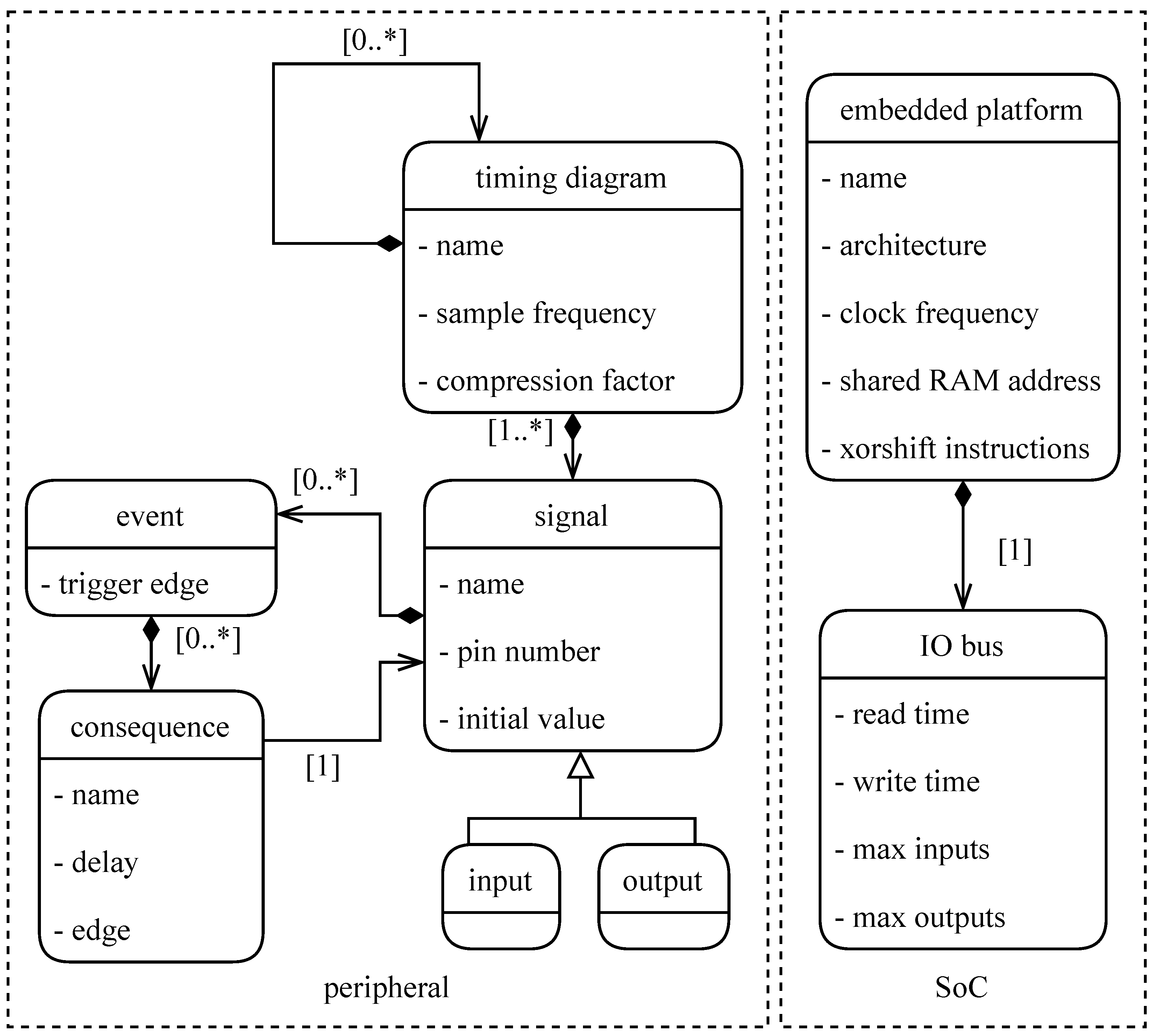
6]. The developed model consists of two main components: firstly, a definition of the sequence of events necessary to accomplish an acquisition and/or actuation (basically a collection of signals and their event triggers). This model definition can be deduced from the timing diagram, which can typically be found in the ADC/DAC datasheet. Secondly, a definition of the platform that will be used for acquisition or actuation along with its specifications such as, e.g., clock frequency, memory size, etc. This combined model, as can be seen in a simplified form in
Figure 2, contains all the information that can not be defined in a generic manner. Two independent components are necessary for a functional acquisition system, namely a timing diagram (on the left in
Figure 2) and an embedded platform (on the right in
Figure 2). The timing diagram consists of a set of signals, which in turn contains a sequence of events that trigger signal transitions. The definition of the event sequence only includes a single acquisition sequence, such that the timing can be matched to the defined sampling frequency. The most important features of the embedded platform are the architecture and the clock frequency. The architecture definition is used to select the correct compiler and combine the correct libraries with the generated timing. The clock frequency is used to match the timing diagram with the embedded platform. Furthermore, the IO timings are used to evaluate whether all defined signal transitions are feasible on the desired platform. From the specifications of these two components a fully functional firmware is generated using model-to-text generator tool Acceleo [
7]. This way the model serves as an abstraction layer between the designer, e.g., a system engineer, and the actual required programming knowledge. Thanks to the modular construction, the component models can be interchanged with different platforms and/or acquisition sequences, enabling easy reusability and portability of the defined components. From this step onwards, all steps are performed behind the scenes by the model transformation. This means that the abstraction level lies at the model definition. The complete version of the presented class diagram can be found in the publicly available repository [
5].
4. Code Generation for Embedded Compressive Sensing
The purpose of this research does not lie in proving the added value of CS, since there is plenty of literature available on that topic [
2,
4,
8,
10,
11,
12,
13,
14,
15,
16]. However, significant steps forward can still be made in the development process of acquisition systems implementing the proposed embedded CS strategies [
2]. In current approaches, the implementation of a CS strategy is manually programmed and therefore, as mentioned above, arduous and error prone. For this reason an option for CS is added to our model-based code generator [
5]. To avoid that the user of the generator has to acquire an intricate knowledge of the foundations of CS, the generator automatically modifies a traditional acquisition sequence in compliance with Shannon’s theorem. This has the additional advantage that the user can easily switch CS on and off without having to redefine the acquisition sequence model. In the research of O’Connor [
2] an algorithm is presented for embedded CS. This research differs from most of the existing research in the sense that it presents a CS algorithm, which makes sense to implement on an embedded device. Whereas most of the research starts from a fully acquired dataset and then experiments with imposing a random cherry-picking scheme on the entire set, implementing this on an embedded device would require plenty of memory, whilst most embedded devices are memory-constrained. The algorithm used in the research of O’Connor starts from the assumption that the random cherry-picking from an existing dataset can be replaced with the introduction of a random but limited amount of skipped samples during acquisition. Obviously, this will have an impact on the overall randomness of the CS dataset, and as such this has an impact on the RIP [
9]. The assumption implies that the pseudo-random dataset will also comply with the RIP for most signals and as such enable a successful reconstruction. For the calculation of the pseudo-random amount of skipped samples
d, the assumption is made that for an undersampling factor of
n, the dataset is still sufficiently random if
d is uniformly distributed between 0 and
skipped samples, with
n as the compression factor.
The model generator is developed in such a way that the amount of clock ticks necessary for the defined timing diagram are counted on generation. From that result, the amount of clock ticks of delay required to match the defined sampling frequency is provided by no operation instructions (NOPs). To do this in a constant and stable manner, the exact amount of instructions needs to be known, constant and stable. This calculation has been extended with the amount of instructions necessary for the calculation of
d. When implementing this on an embedded device’s coprocessor, where every additional action adds a delay, the main difficulty is that adding a pseudo-random number generation between samples adds a certain amount of code. The algorithm for this generation should be constant in execution time, to prevent having to evaluate the timing after every sample. To this end, the calculation of a pseudo-random value
x is done using an xorshift algorithm as proposed by Marsaglia [
17]. This pseudo-random value
x is then modulo divided by twice the undersampling factor
n. Due to the combination of the pseudo-random generation and the modulo division of the pseudo-random number
x, the calculated delay values are uniformly distributed resulting in an undersampling factor
n. This leads to an average acquisition rate equal to the traditional sample frequency divided by the undersampling factor
n. Since the xorshift algorithm requires xor and bitwise shift operations -what’s in a name-, it is easily implemented on different embedded platforms. The only platform-specific part caused by this approach is the amount of clock cycles required for the pseudo-random number calculation. This can vary slightly on different processors due to pipelining, memory caching, etc., but can be assumed constant for a specific processor and is therefore defined in the platform model as part of the platform specification. This also implies that once a platform has been implemented in the generator for CS, it can be reused in combination with new or existing acquisition sequences without having to develop any additional platform-specific resources.
5. Generated Firmware in Action
To verify the robustness of both the implemented CS strategy and the generated firmware using the model-based code generator, a setup was developed to simulate a real acquisition scenario. The setup uses a National Instruments DAQ unit to generate a test signal. To ensure that the signal is sufficiently sparse to meet the RIP for CS recovery, a combination of three sine waves was used, at 1 kHz, 21 kHz and at 43 kHz. The simplicity of this signal was chosen as such since the theory behind CS and its recovery capabilities are not the main scope of this paper. The use case is intended to demonstrate the time-wise accuracy of the generated firmwares.
This test signal is coupled to a combination of a custom PCB with buffer amplifiers, sampling filters, an ADS8556 ADC [
18], and the direct IO inputs of the Beaglebone Black’s coprocessor [
19]. This combination was manually developed by Verreycken et al. [
20] for classical Nyquist sampling. The firmware for this project was manually developed in approximately 15 working days by an engineer skilled for the job. The development effort invested in this project illustrates that even for acquisition systems without CS, the manual programming and development of such a system is arduous, error-prone and requires intricate low-level hardware and software knowledge. As a first test, the model-based code generator is used to generate a traditional Shannon-conform acquisition sequence for the ADS8556. This firmware has been thoroughly evaluated in previous work [
1] and will serve as the ground truth for the CS firmware to be compared with. The development of the ground truth firmware using the code generator took about three hours, including testing. Thus, the code generator offers an improvement with a factor 30 when compared to manual firmware development.
5.1. Time-Wise Accuracy
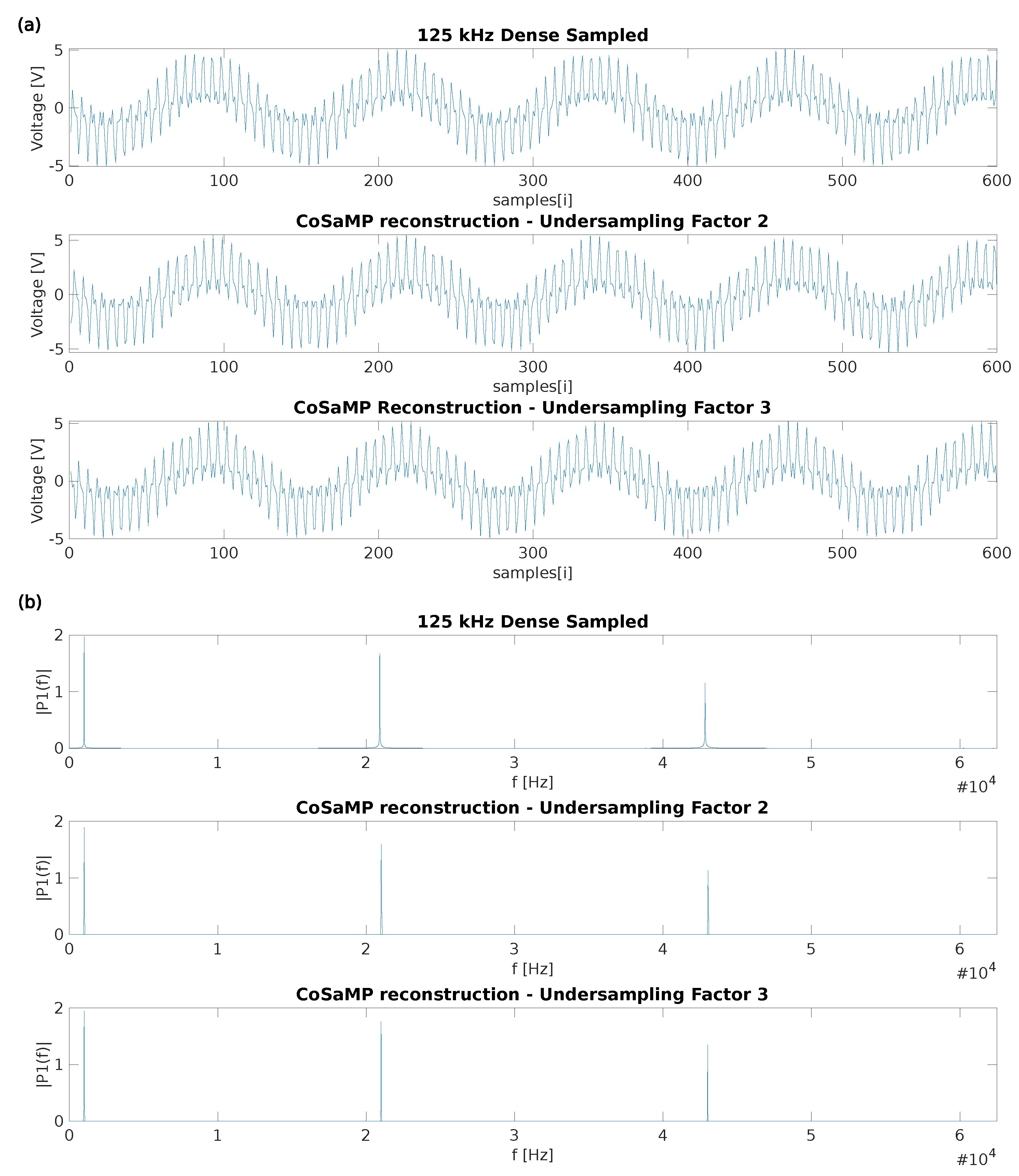
To test the CS generation, the CS option was enabled in the generator, which requires practically no additional effort. To prove that the generator functions well for different undersampling factors n whilst maintaining a successful reconstruction, at first two cases were tested, being
n = 2 and
n = 3. A comparison of the results using the three auto-generated acquisition firmwares can be seen in
Figure 3. As mentioned in
Section 3, the undersampled data reconstruction was done using the CoSaMP algorithm [
10]. The top figure presents the time domain values for the original signal, as well as its reconstructions for the two tested values of
n. The bottom figure shows the frequency domain values for the same three configurations. Let us discuss these results. Since the results for all three cases exactly match the generated sine waves’ frequencies (1, 21 and 43 kHz) the time-wise accuracy of the captured samples can be considered “on-the-clock-true”. If a mismatch between the defined and actual sampling frequency would be present, the calculated signal frequencies would be shifted, which is currently not the case. For the lowest frequency (1 kHz) a small difference in peak amplitude is visible for undersampling factor two. To evaluate this effect, different sections of the fully sampled signal were reconstructed. This revealed a certain tolerance on the peak of up to five percent when compared with the dense sampled peak amplitude. This effect is significantly smaller on the higher undersampling factors. This is probably due to the proposed approach not generating a sufficiently random sensing matrix for such a low undersampling factor, and therefore not complying with the RIP. For this reason, a minimum compression factor
n of three is recommended, to guarantee an accurate reconstruction.
From this comparison, the conclusion can be drawn that the generator is successfully generating firmware for CS purposes. The success of the reconstruction demonstrates that the proposed pseudo-random sampling method is appropriate for CS reconstruction using previously established reconstruction methods [
10].
5.2. Compression Robustness
Secondly, to explore the boundaries of CS for the used test signal, the cross-correlation factor between the Nyquist-sampled test signal and its undersampled version is calculated. The undersampling factor for this calculation ranges from 1 to 128. Due to the recovery success being calculated as the likelihood of an accurate reconstruction, a Monte Carlo simulation was used with 100 iterations per undersampling factor, using a different pseudorandom dataset for each simulation [
21]. As an indicator for the reconstruction’s success, the minimum, maximum and mean of the cross-correlation factors of each reconstruction with the original Nyquist-sampled signal are used. In
Figure 4, the results are demonstrated. The figure demonstrates that up until an undersampling factor of forty-four, the reconstruction achieves a mean value of 99.5% cross-correlation with the original signal. Above an undersampling factor of 44, the mean value of the cross-correlation factors drops below 99.5%. Due to the sparsity constraints inherent to CS, this is of course a signal specific result, and as such cannot be used to draw fixed conclusions on general limitations of the undersampling factor. However, including this simulation with a well-selected range of desired signals to be captured with the generated firmware, can help the designer to make an appropriate choice for the undersampling factor definition in the generator model.
6. Synchronization between CS Setups
Synchronization is a recurrent issue in measurement setups due to the multimodality of typical sensing setups (e.g., video, audio and motion) [
22,
23,
24,
25]. To validate the proposed synchronization approach, a test scenario is elaborated using a combination of two identical acquisition devices, two digital stethoscopes capturing diastolic sound and a synchronization signal. The stethoscopes are each connected to a separate acquisition device. A second channel on the acquisition device is used to capture the synchronization signal as portrayed in
Figure 5. The use case is designed to evaluate and address the issue of synchronization for CS in particular.
All channels have been captured with an undersampling factor
n of 3 and a defined sampling frequency of 125 kHz, that leads to an average sampling frequency of 41.667 kHz when applying Equation (
8) found in
Section 4. The synchronization signal is a pseudo-random block pulse generated using a National Instruments USB-6363 DAQ. This approach was chosen due to previous success in synchronization research from Laurijssen et al. [
26]. This research formulated the minimum and maximum period between signal transitions of the pseudo-random synchronization block pulse. However, this approach assumes traditional Nyquist sampling. Since it is crucial that no signal transitions are missed, the minimum and maximum periods are impacted by the undersampling factor. The minimum period or lower boundary has to be a value in proportion with the maximum number of skipped samples. Combining the conclusion from the research of Laurijssen et al. with the maximum number of skipped samples (two times the undersampling factor), the assumption is made that a proper synchronization can be guaranteed starting from a minimal transition time (in sample periods) of at least four times the undersampling factor. To determine the maximum period or upper boundary, a similar assumption is made. The research from Laurijssen et al. suggested that at least ten transitions need to be present in the synchronization signal. As such the upper boundary is dependent on the captured signal length. Dividing the captured signal length by the product of the minimum amount of transitions with twice the undersampling factor gives us the assumed upper boundary for successful synchronization. These assumptions are discussed and tested in detail in
Section 6.1.
The four channels are reconstructed using the CoSaMP CS reconstruction algorithm. The reconstruction of the captured stethoscope data is presented in
Figure 6. Since the two acquisition devices are separately controlled, the data is unsynchronized. To synchronize the two measurements, the proposed approach is to reconstruct the undersampled synchronization block pulse, and cross-correlate the two captures of the synchronization signal. The calculated timeshift between the two signals is then applied to the signal of interest to achieve synchronization as displayed in
Figure 6. Since the cross-correlation demonstrates a single peak with a sufficient difference in amplitude with other peaks in the data, the conclusion can be made that synchronization up to the resolution of a single sample is possible within the defined boundaries using the proposed approach. Since the tolerance on the synchronization is use-case dependent, the simulation presents a wide range of possible settings to provide a full image of the possible solutions for the designer’s synchronization issue.
6.1. Synchronization Robustness
To justify the chosen settings, a Monte Carlo simulation was elaborated to demonstrate the accuracy and limitations of the proposed method [
21].
This simulation evaluates the difference in the calculated synchronization timeshift between the traditional Nyquist sampled approach and the CS approach using synchronization signals of 4000 and 18,000 dense samples. The results of this simulation are presented in
Figure 7. As a ground truth, the traditional Nyquist sampled data is used. To determine the alignment error, the results obtained using the undersampled signals are compared with the results obtained using the ground truth signal. The simulation runs for one-hundred iterations with a new pseudo-random synchronization signal for every iteration. This synchronization signal is shifted by one-hundred samples to simulate an unsynchronized system with two acquisition devices. The signals are then undersampled with an undersampling factor ranging from one to forty-four. The undersampled signals are then reconstructed and synchronized using the proposed approach. The top panel of
Figure 7 presents the maximum alignment error for a signal of 4000 samples, meaning the maximum difference over one-hundred iterations in calculated timeshift between the synchronization calculation using traditionally sampled signals and the same calculation using undersampled signals. The lower boundary for the minimum amount of sample periods per transition is set as four times the undersampling factor. The upper boundary ensures that at least ten transitions are captured, and therefore depends on the amount of acquired signal samples. The lower panel of
Figure 7 demonstrates the impact of the signal length on the synchronization accuracy and boundaries by using a signal length of 18,000 samples. Using a larger signal length places the upper boundary higher, leading to a higher achievable maximum undersampling factor with a single sample period synchronization accuracy. This figure clearly demonstrates that the previously mentioned upper and lower boundaries provide appropriate limits to ensure valid synchronization with an accuracy up to one sample period. The maximum alignment error proves to be a good measure for the synchronization accuracy and can therefore be used by the system designer to make a well-founded parameter selection in the model. The comparison with the ground truth signal demonstrates that the proposed approach enables synchronization up to a single clock period when the parameters are selected within the set boundaries.


 ,
, 


