


Fiber-Optic Sensors (FOS) for Smart High Voltage Composite Cables—Numerical Simulation of Multi-Parameter Bending Effects Generated by Irregular Seabed Topography


Abstract
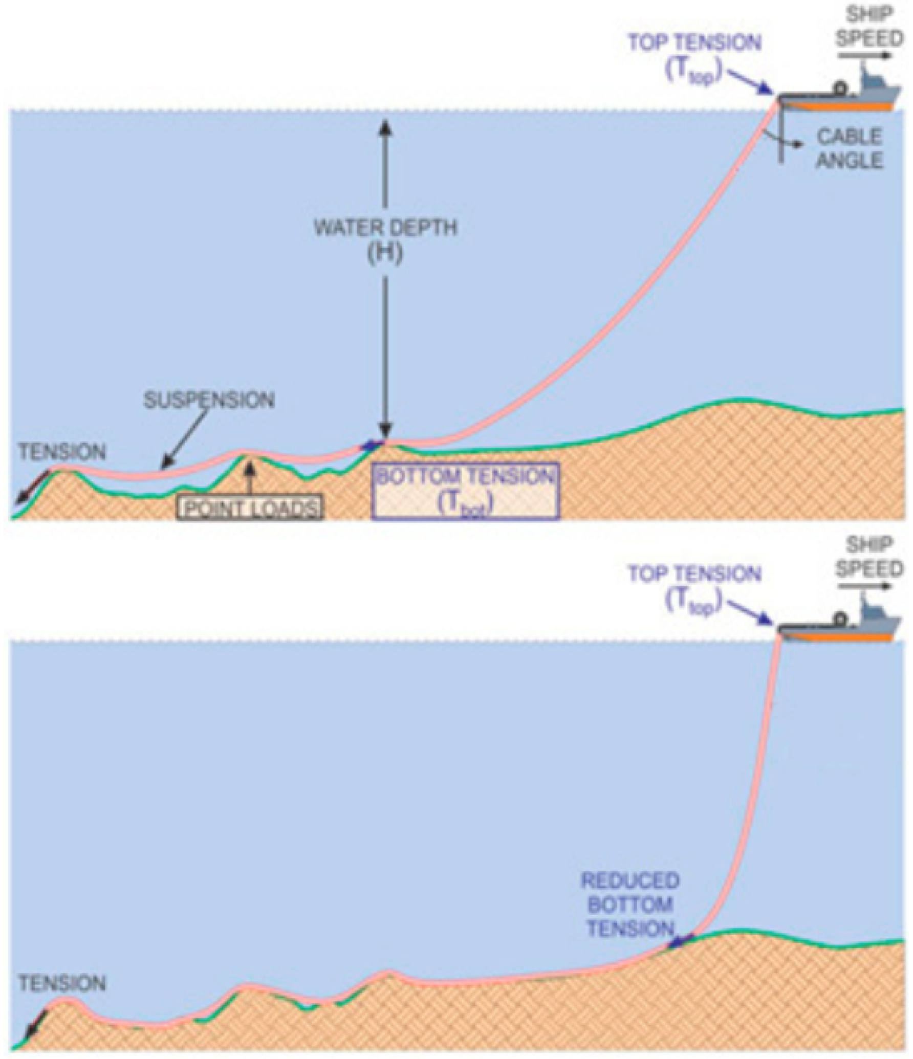
1. Introduction

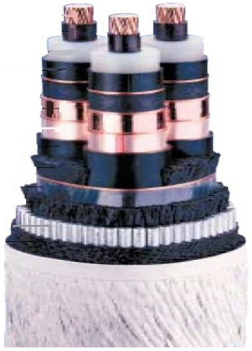
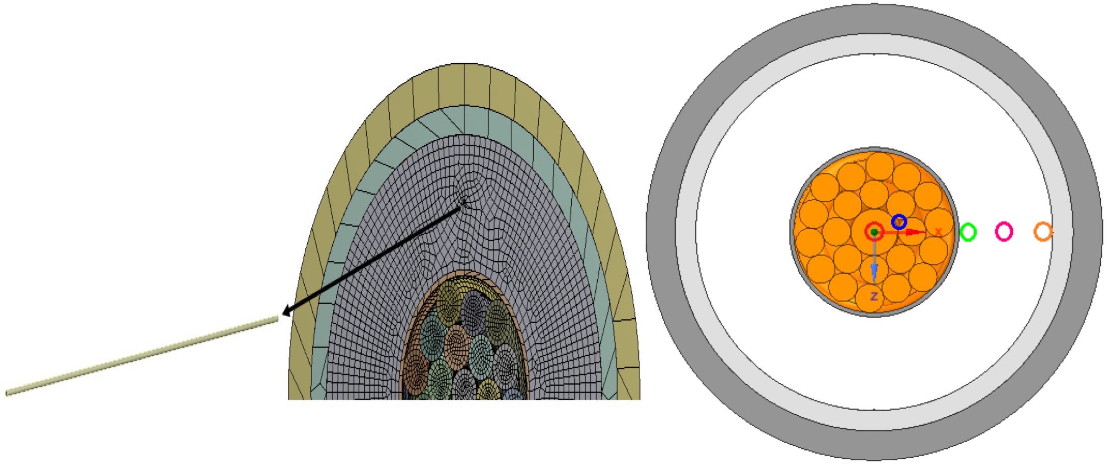
2. Geomteric Model
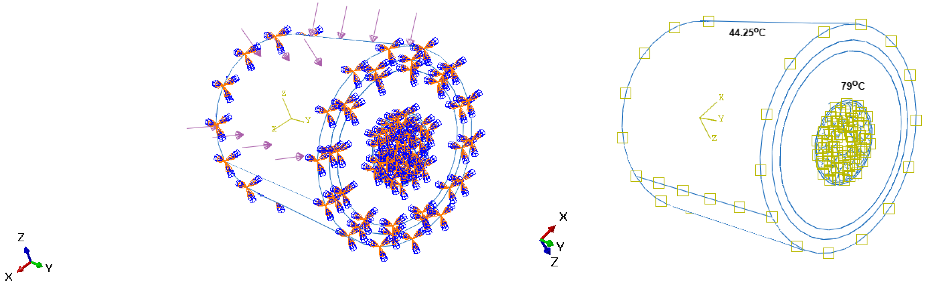
3. Mechanical Boundary Conditions
4. Thermal Boundary Condition
5. Results and Analysis
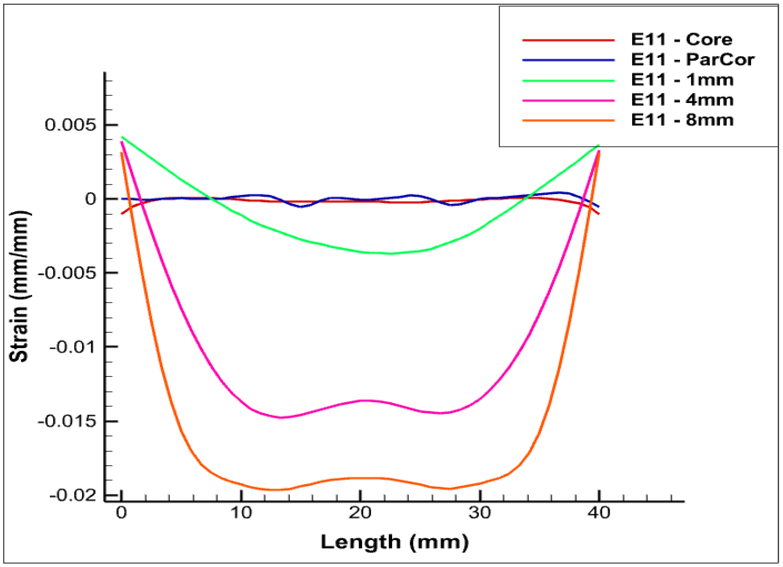
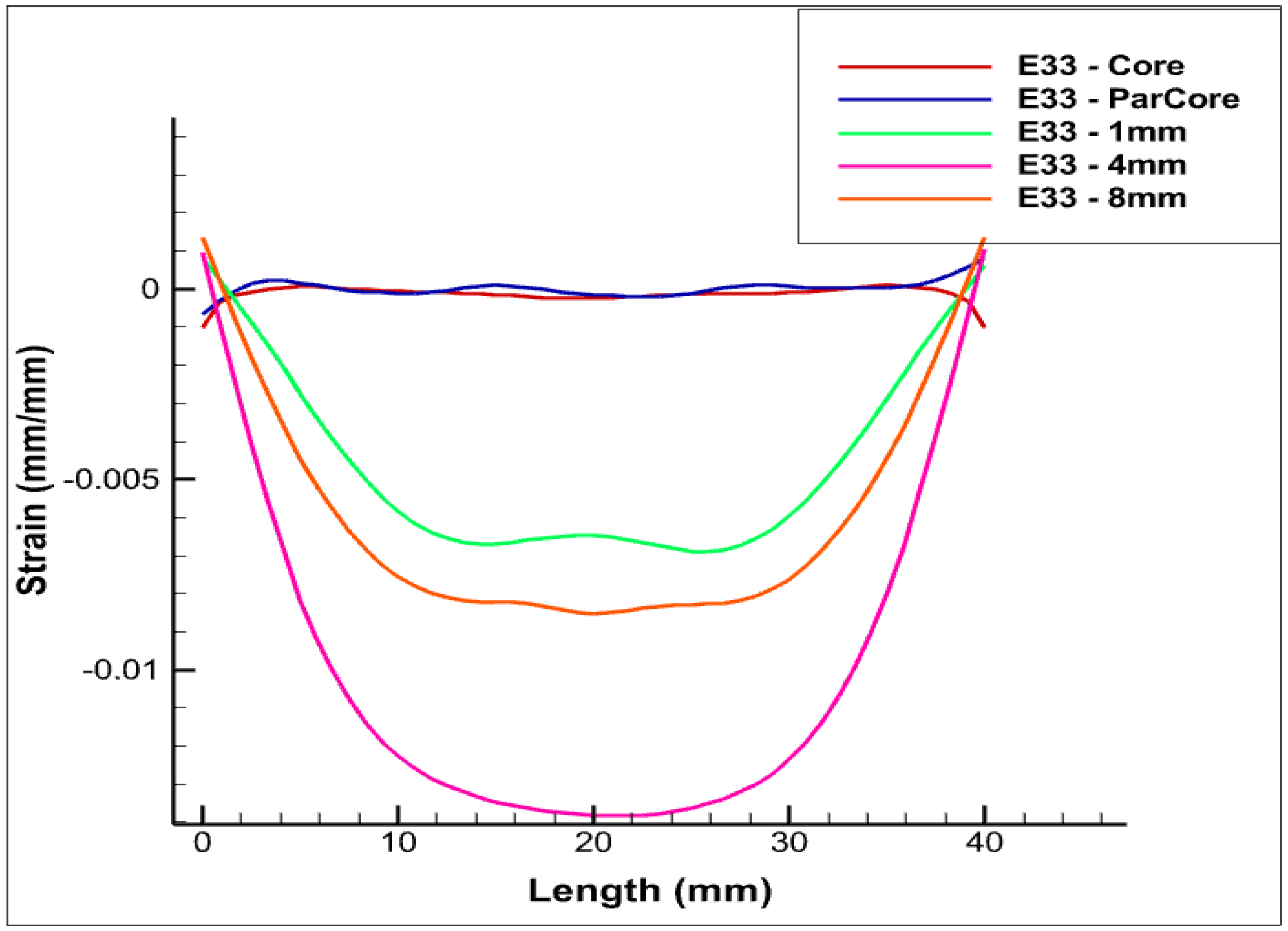
5.1. Test Case A—Positioning of Linear FOS in Parallel Positioning with Varying Length from the Core
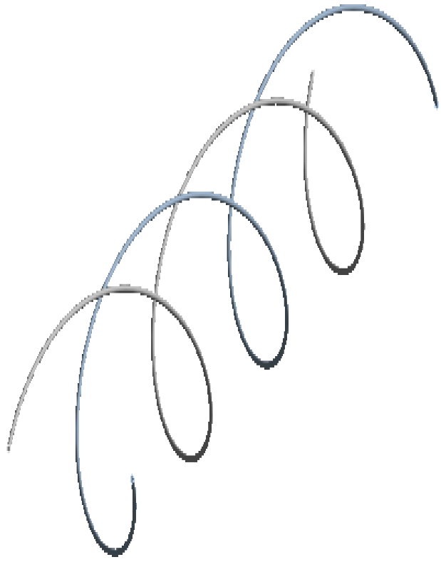
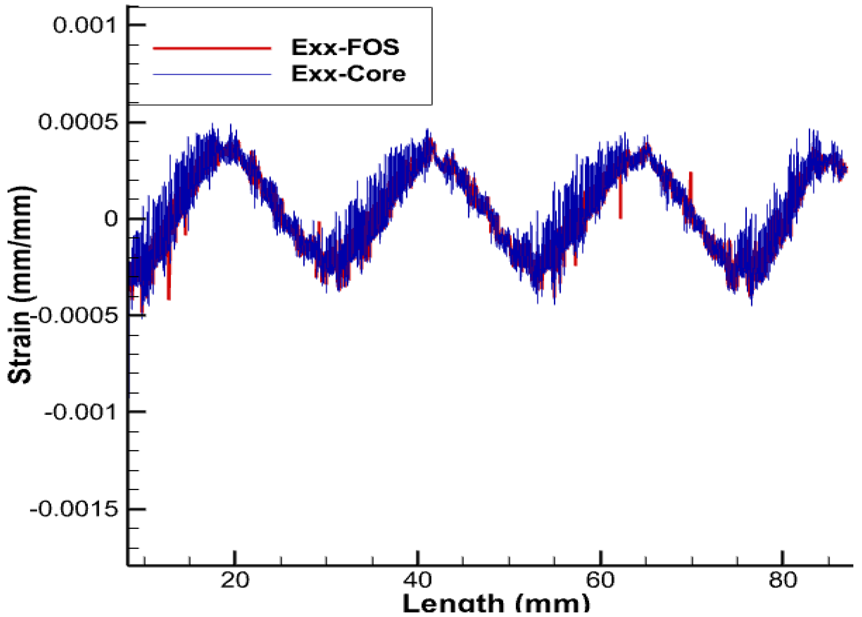
5.2. Test Case B: Placement of FOS Helical Wound around the Complete Core
6. Conclusions and Discussion
Author Contributions
Funding
Data Availability Statement
Acknowledgments
Conflicts of Interest
References
- Drissi-Habti, M.; Neghinal, A.; Manepalli, S.; Carvelli, V.; Bonamy, P.-J. Concept of Placement of Fiber-Optic Sensor in Smart Energy Transport Cable under Tensile Loading. Sensors 2022, 22, 2444. [Google Scholar] [CrossRef] [PubMed]
- Drissi-Habti, M.; Sriharsha, M.; Neghinal, A.; Carvelli, V.; Bonamy, P.-J. Numerical Simulation of Aging by Water-Trees of XPLE Insulator Used in a Single Hi-Voltage Phase of Smart Composite Power Cables for Offshore Farms. Energies 2022, 15, 1844. [Google Scholar] [CrossRef]
- Drissi-Habti, M.; Raman, V.; Khadour, A.; Timorian, S. fiber-optic Sensor Embedment Study for Multi-Parameter Strain Sensing. Sensors 2017, 17, 667. [Google Scholar] [CrossRef] [PubMed]
- Raman, V.; Drissi-Habti, M.; Guillaumat, L.; Khadhour, A. Numerical simulation analysis as a tool to identify areas of weakness in a turbine wind-blade and solutions for their reinforcement. Compos. Part B Eng. 2016, 103, 23–39. [Google Scholar] [CrossRef]
- Raman, V.; Drissi-Habti, M.; Limje, P.; Khadour, A. Finer SHM-coverage of inter-plies and bondings in smart composite by dual sinusoidal placed distributed optical fiber sensors. Sensors 2019, 19, 742. [Google Scholar] [CrossRef]
- Raman, V.; Drissi-Habti, M. Numerical simulation of a resistant structural bonding in wind-turbine blade through the use of composite cord stitching. Compos. Part B Eng. 2019, 176, 107094. [Google Scholar] [CrossRef]
- Drissi-Habti, M.; Das, R.-J.; Vijayaraghavan, S.; Ech-Cheikh, F. Numerical Simulation for Void Coalescence (Water Treeing) in XLPE Insulation of Submarine Composite Power Cables. Energies 2020, 13, 5472. [Google Scholar] [CrossRef]
- Raman, V.; Drissi-Habti, M.; Khadour, A. fiber-optic Sensor Embedment Study for Multi-Parameter Strain Sensing in Smart Composites. In Proceedings of the American Society for Composites—Thirty-Second Technical Conference, West Lafayette, Indiana, 23–25 October 2017. [Google Scholar]
- Matine, A.; Drissi-Habti, M. On-Coupling Mechanical, Electrical and Thermal Behavior of Submarine Power Phases. Energies 2019, 12, 1009. [Google Scholar] [CrossRef]
- Karimirad, M. Offshore Energy Structures: For Wind Power, Wave Energy and Hybrid Marine Platforms; Springer: Cham, Switzerland, 2014. [Google Scholar]
- Gulski, E.; Anders, G.J.; Jongen, R.A.; Parciak, J.; Siemiński, J.; Piesowicz, E.; Paszkiewicz, S.; Irska, I. Discussion of electrical and thermal aspects of offshore wind farms’ power cables reliability. Renew. Sustain. Energy Rev. 2021, 151, 111580. [Google Scholar] [CrossRef]
- Alcorn, R.; O’Sullivan, D. Electrical Design for Ocean Wave and Tidal Energy Systems; IET—Institution of Engineering and Technology: Stevenage, UK, 2013. [Google Scholar]
- Grant Agreements Number 213633—Project Title: Components for Ocean Renewable Energy—Specification of Power Umbilical Components. 2009. Available online: https://cordis.europa.eu/project/id/213633 (accessed on 1 October 2022).
- Bending Restrictors and Stiffeners Brochures. Available online: http://www.trelleborg.com (accessed on 1 October 2022).
- Diumegard, C.; Fellows, P. Installation of metallic tube umbilicals in 3000 meters water. In Proceedings of the Offshore Technology Conference, Houston, TX, USA, 5–8 May 2003. [Google Scholar]
- Ansari, F. Structural health monitoring with fiber-optic sensors. Front. Mech. Eng. China 2009, 4, 103–110. [Google Scholar] [CrossRef]
- Ramakrishnan, M.; Ginu, R.; Semenova, Y.; Farrell, G. Overview of fiber-optic sensor technologies for strain/temperature sensing applications in composite materials. Sensors 2016, 16, 99. [Google Scholar] [CrossRef] [PubMed]
- Napieralski, P.; Napieralska Juszczak, E.; Zeroukhi, Y. Nonuniform distribution of conductivity resulting from the stress exerted on a stranded cable during the manufacturing process. IEEE Trans. Ind. Appl. 2016, 52, 3886–3892. [Google Scholar] [CrossRef]
- Zhang, Y.; Chen, X.; Zhang, H.; Liu, J.; Zhang, C.; Jiao, J. Analysis on the temperature field and the ampacity of XLPE submarine HV cable based on electro-thermal-flow multiphysics coupling simulation. Polymers 2020, 12, 952. [Google Scholar] [CrossRef] [PubMed]
- Aras, F.; Biçen, Y. Thermal modelling and analysis of high-voltage insulated power cables under transient loads. Comput. Appl. Eng. Educ. 2013, 21, 516–529. [Google Scholar] [CrossRef]
- Pilgrim, J.; Lewin, P.; Gorwadia, A.; Waite, F.; Payne, D. Quantifying possible transmission network benefits from higher cable conductor temperatures. IET Gener. Transm. Distrib. 2013, 7, 636–644. [Google Scholar] [CrossRef]
- Robinson, G. Ageing characteristics of paper-insulated power cables. Power Eng. J. 1990, 4, 95–100. [Google Scholar] [CrossRef]
- Bo, Y.; Wu, K.; Zheng, Z.; Sun, W.; Wang, Y.; Yang, S.; Liang, R.; Feng, L. Study on improving the current carrying capacity of power cable in real-time operating environment. In Proceedings of the 2016 China International Conference on Electricity Distribution (CICED), Xi’an, China, 10–13 August 2016; pp. 1–4. [Google Scholar]
- Yang, L.; Hu, Z.; Hao, Y.; Qiu, W.; Li, L. Internal temperature measurement and conductor temperature calculation of XLPE power cable based on optical fiber at different radial positions. Eng. Fail. Anal. 2021, 125, 105407. [Google Scholar] [CrossRef]
- Mamatsopoulos, V.A.; Michailides, C.; Theotokoglou, E.E. An Analysis Tool for the Installation of Submarine Cables in an S-Lay Configuration Including “In and Out of Water” Cable Segments. J. Mar. Sci. Eng. 2020, 8, 48. [Google Scholar] [CrossRef]
- Cao, L.; Zhong, L.; Li, Y.; Gao, J.; Chen, G. Crosslinking Dependence of Direct Current Breakdown Performance for XLPE-PS Composites at Different Temperatures. Polymers 2021, 13, 219. [Google Scholar] [CrossRef]
- Al Robaidi, A.M.I.N.; Al Khateeb, S.; Dweiri, R.; Gaghbeer, T. The Effect of Radiation on the Thermal Expansion of Kaolin Nano Filled-XLPE Materials. 2012. Available online: https://www.ijser.org/researchpaper/The-effect-of-radiation-on-the-thermal-expansion-of-kaolin-nano-filled–XLPE-materials.pdf (accessed on 1 October 2022).
- Available online: https://seapower.vn/upload/file/iec-60287-1-1-9538-taptin0.pdf (accessed on 1 October 2022).
- di Sante, R. Fibre Optic Sensors for Structural Health Monitoring of Aircraft Composite Structures: Recent Advances and Applications. Sensors 2015, 15, 18666–18713. [Google Scholar] [CrossRef]
- Petrie, C.M.; Sridharan, N.; Subramanian, M.; Hehr, A.; Norfolk, M.; Sheridan, J. Embedded metallized optical fibers for high temperature applications. Smart Mater. Struct. 2019, 28, 055012. [Google Scholar] [CrossRef]
- Available online: https://www.forc-photonics.ru/en/fibers_and_cables/Cu_coated_fibers/1/381 (accessed on 1 October 2022).


| Materials | Density (kg/m3 | Young’s Modulus (MPa) | Poisson’s Ratio | Thermal Conductivity (W/mK) |
|---|---|---|---|---|
| Copper | 8300 | 1.1 | 0.3 | 370 |
| Semi-Conducting Polymer | 1000 | 1500 | 0.4 | 0.1 |
| XLPE | 955 | 1250 | 0.4 | 0.28 |
| Polyethelene Black | 958 | 1050 | 0.4 | 0.2 |
| Acrylate | 950 | 2700 | 0.35 | 0.2 |
| Polymide | 1100 | 3000 | 0.42 | 0.8 |
Publisher’s Note: MDPI stays neutral with regard to jurisdictional claims in published maps and institutional affiliations. |
© 2022 by the authors. Licensee MDPI, Basel, Switzerland. This article is an open access article distributed under the terms and conditions of the Creative Commons Attribution (CC BY) license (https://creativecommons.org/licenses/by/4.0/).
Share and Cite
Drissi-Habti, M.; Neginhal, A.; Manepalli, S.; Carvelli, V. Fiber-Optic Sensors (FOS) for Smart High Voltage Composite Cables—Numerical Simulation of Multi-Parameter Bending Effects Generated by Irregular Seabed Topography. Sensors 2022, 22, 7899. https://doi.org/10.3390/s22207899
Drissi-Habti M, Neginhal A, Manepalli S, Carvelli V. Fiber-Optic Sensors (FOS) for Smart High Voltage Composite Cables—Numerical Simulation of Multi-Parameter Bending Effects Generated by Irregular Seabed Topography. Sensors. 2022; 22(20):7899. https://doi.org/10.3390/s22207899
Chicago/Turabian StyleDrissi-Habti, Monssef, Abhijit Neginhal, Sriharsha Manepalli, and Valter Carvelli. 2022. "Fiber-Optic Sensors (FOS) for Smart High Voltage Composite Cables—Numerical Simulation of Multi-Parameter Bending Effects Generated by Irregular Seabed Topography" Sensors 22, no. 20: 7899. https://doi.org/10.3390/s22207899
APA StyleDrissi-Habti, M., Neginhal, A., Manepalli, S., & Carvelli, V. (2022). Fiber-Optic Sensors (FOS) for Smart High Voltage Composite Cables—Numerical Simulation of Multi-Parameter Bending Effects Generated by Irregular Seabed Topography. Sensors, 22(20), 7899. https://doi.org/10.3390/s22207899