
Directly Matching an MMIC Amplifier Integrated with MIMO Antenna through DNNs for Future Networks


Abstract
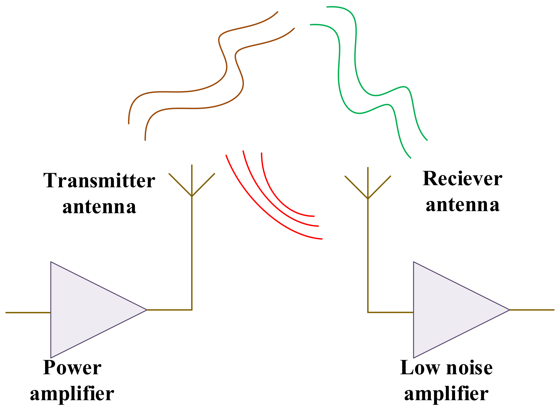
:1. Introduction
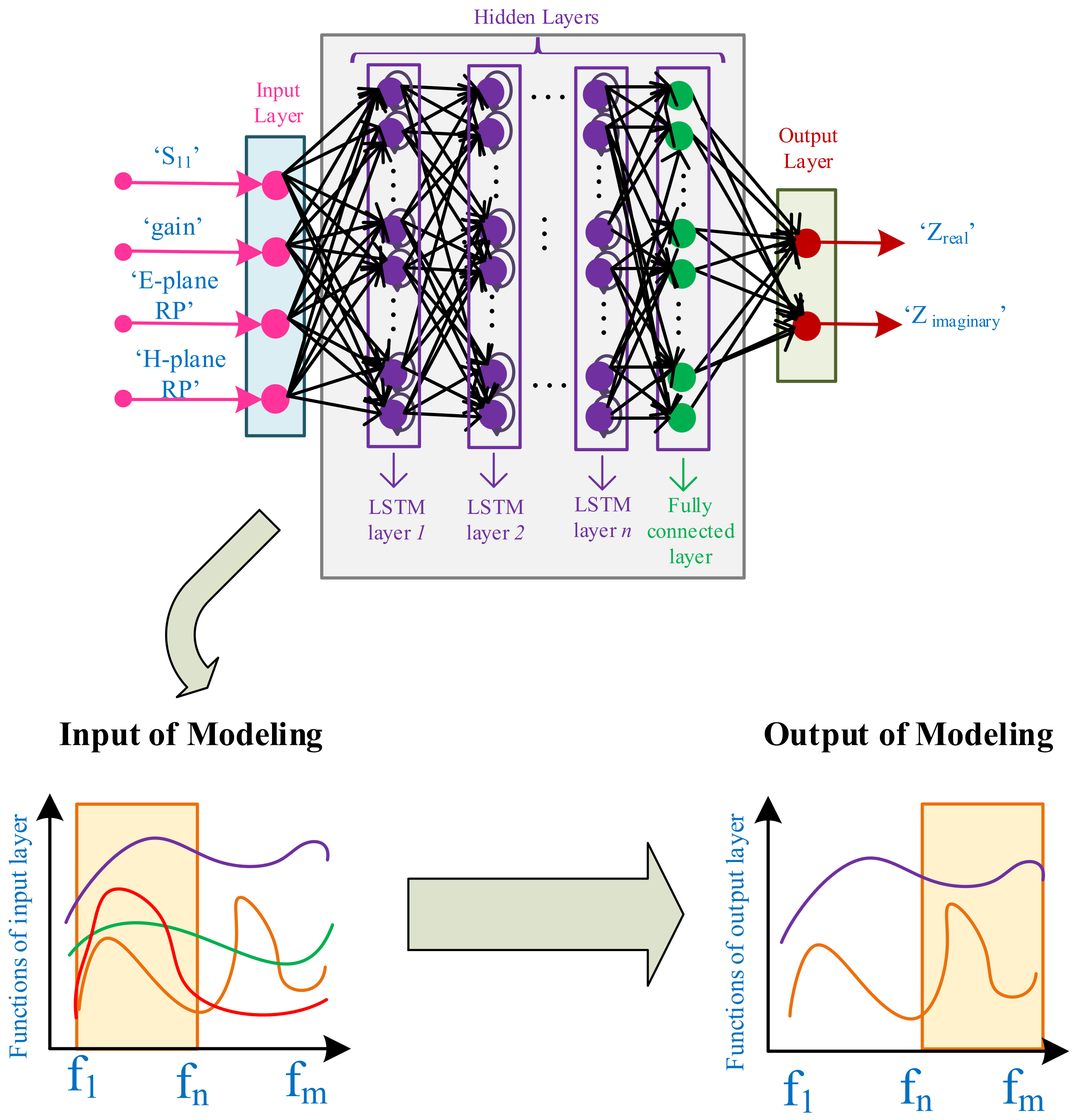
- Modeling the antenna with LSTM-based DNN leading to estimate the real and imaginary parts of load impedances over the large bandwidth;
- Directly matching the antenna into the drain’s optimal impedance;
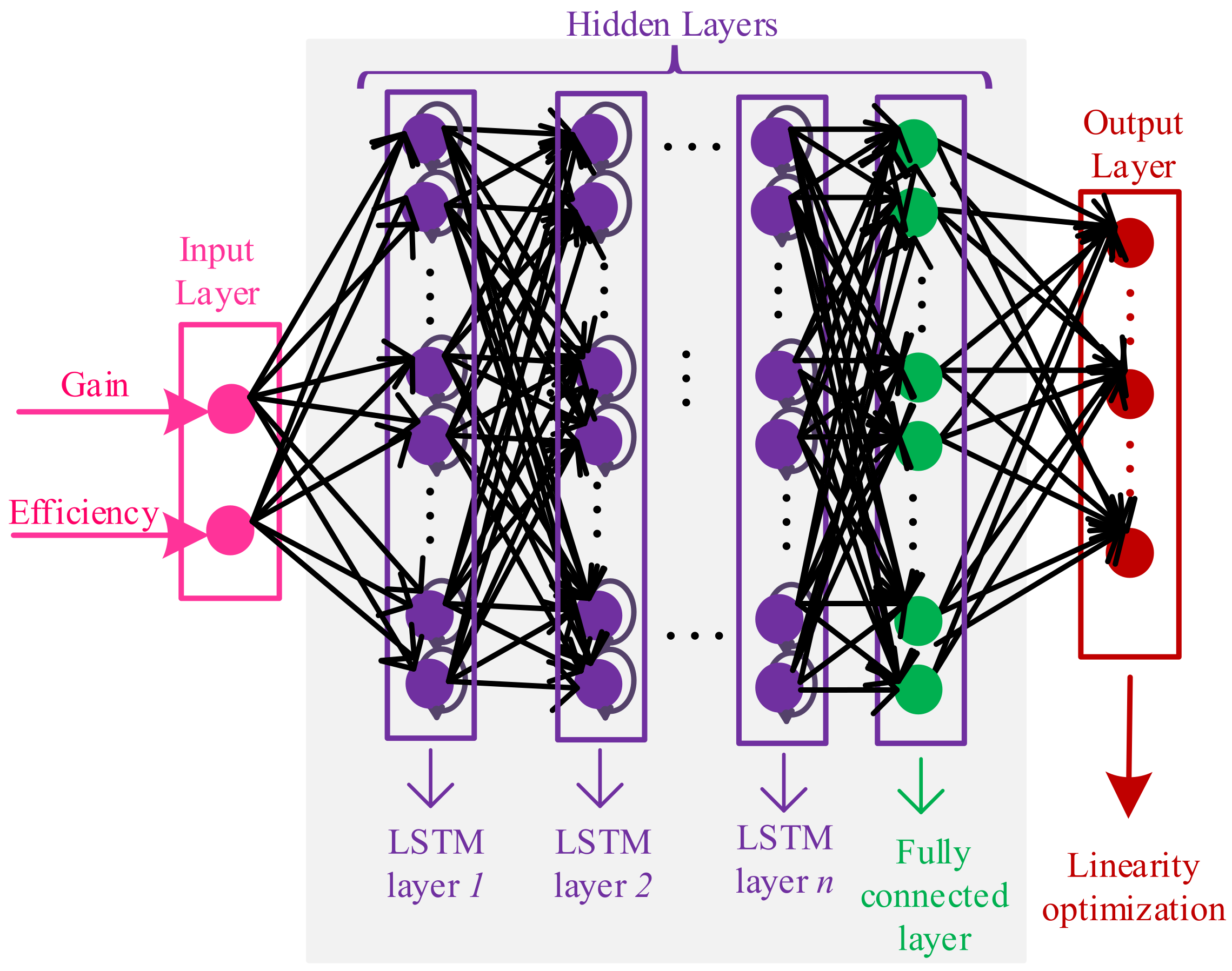
- Modeling the PA with the LSTM-based DNN through multivariate Newton’s method;
- Linearity improvement of the overall system by cointegration of antenna and amplifier as passive and active devices, respectively.
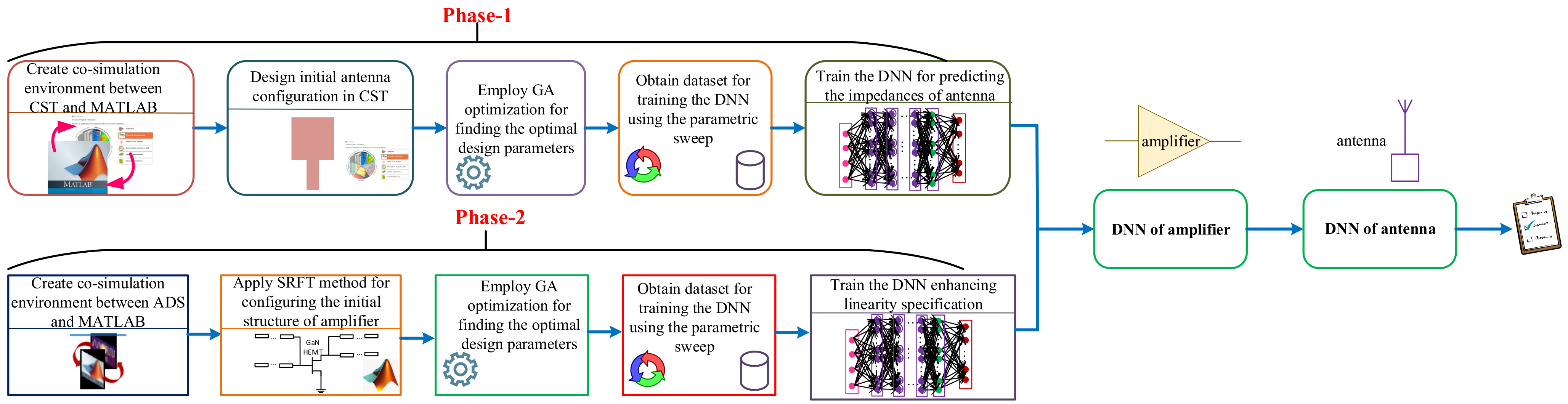
2. Proposed Optimization Method
2.1. LSTM-Based DNN for Modeling Antenna (Phase-1)
2.2. Linearity Optimization through DNN Conjoined to the Modeled Antenna (Phase-2)
| Algorithm 1 Proposed methodology for concurrently modeling antenna and amplifiers in the communication systems leads to enhanced linearity specification. |
| Phase 1 (Antenna modeling) 1: Create co-simulation environment between CST and MATLAB; 2: Design the initial structure of the antenna; 3: Employ the GA method for optimizing the design parameters; 4: Achieve a suitable dataset size, i.e., training and testing dataset, by performing the parametric sweep; 5: Achieve the optimal hyperparameters of DNN used for modeling the antenna through BO method; 6: Train the LSTM-based DNN enabling the prediction of the optimal imepdance that is perfectly matched to the drain impedance transistor over the large frequency band; Phase 2 (PA modeling and optimization in terms of linearity along with the modeled antenna) 7: Construct co-simulation environment between ADS and MATLAB; 8: Configure the PA structure with the SRFT method and run the GA method to obtain the optimal design parameters; 9: Obtain the dataset in terms of gain, efficiency, and IMDs for constructing the LSTM-based DNN; 10: Employ Multivariate Newton’s Method for optimizing the linearity specification; 11: Train the regression DNN for the PA where the optimal hyperparameters are achieved using the BO method; 12: Run the modeled antenna and PA concurrently for optimizing the whole linearity specification of communication systems over the determined frequency band. |
3. Practical Execution for Training Two DNNs
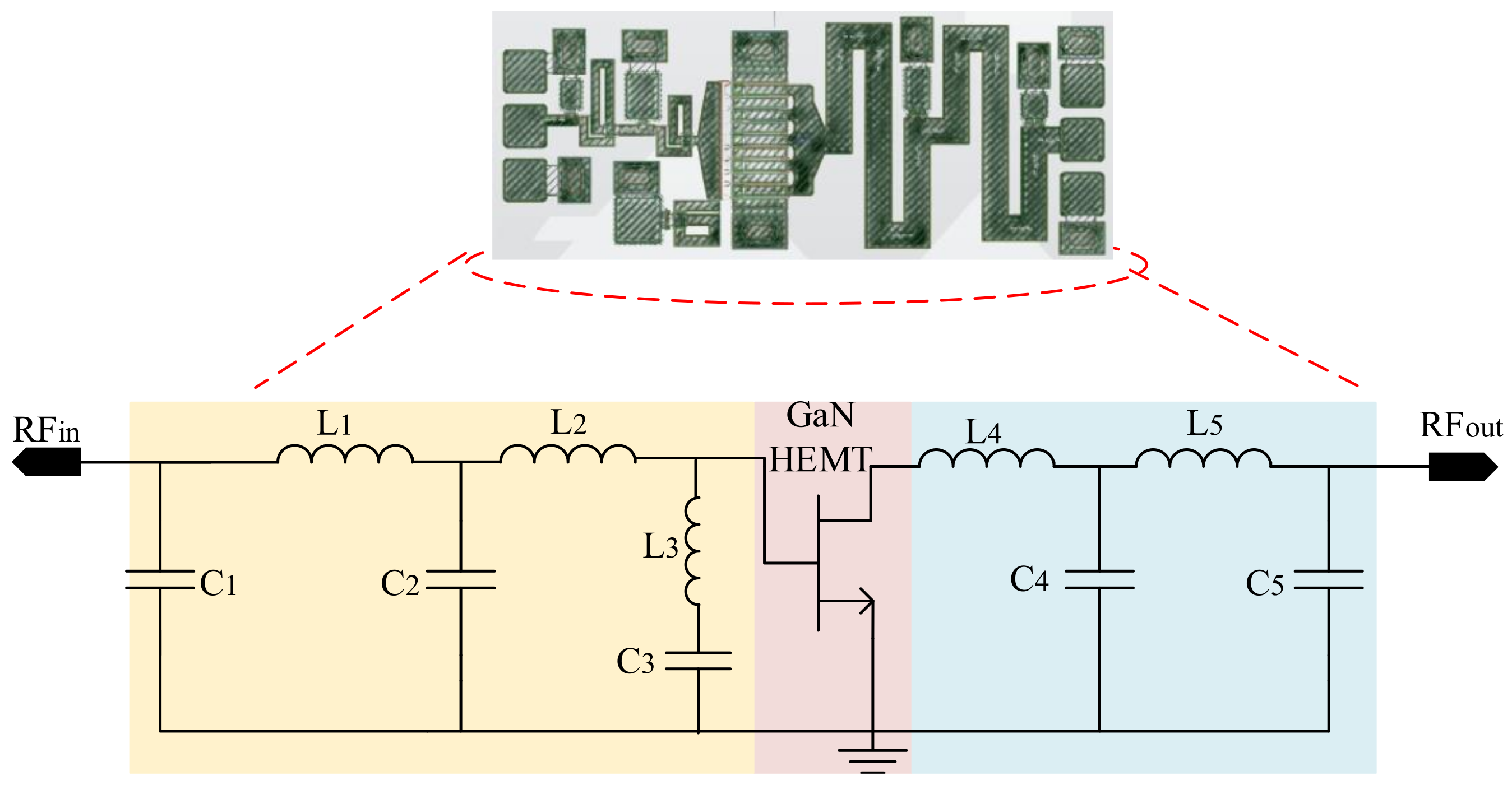
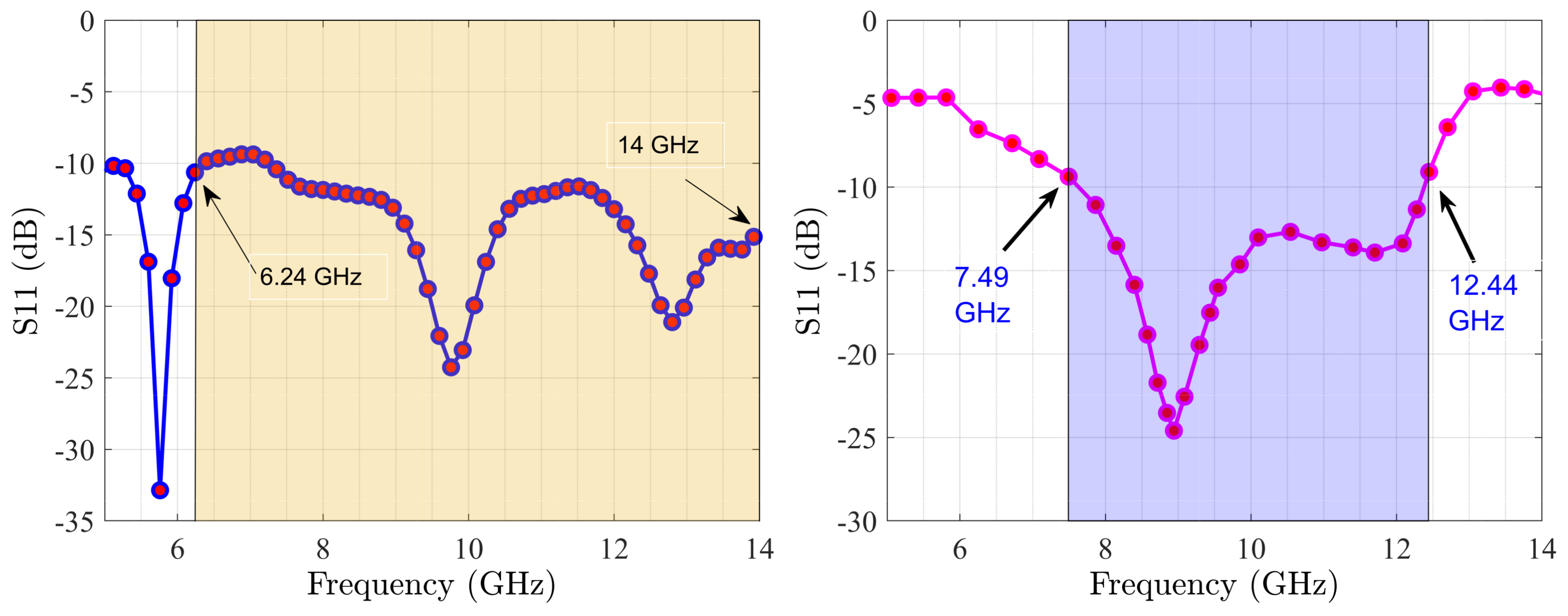
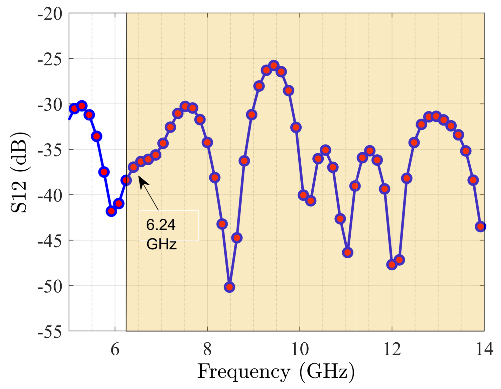
4. Simulation Results of the Optimized System with a Combination of MMIC and MIMO Antenna Designs
5. Conclusions
Funding
Institutional Review Board Statement
Informed Consent Statement
Data Availability Statement
Acknowledgments
Conflicts of Interest
Abbreviations
| ANN | Artificial neural network |
| BO | Bayesian optimization |
| DPD | Digital pre-distortion |
| DNN | Deep neural network |
| EDA | Electronic design automation |
| 5G | Fifth generation |
| GA | Genetic algorithm |
| GaN | Gallium Nitride |
| IMD | Intermodulation |
| LC | Inductor-capacitor |
| LSTM | Long short-term memory |
| MMIC | Monolithic microwave integrated circuit |
| MIMO | Multiple-input multiple-output |
| M | Mean values |
| NOMA | Non-orthogonal multiple access |
| PA | Power amplifier |
| PAE | Power added efficiency |
| ReLU | Rectified linear unit |
| SRFT | Simplified real frequency technique |
| 6G | Sixth generation |
| VLSI | Very-large-scale integration |
| RF | Radio frequency |
| Training input data | |
| Training output data | |
| Testing data | |
| Gain | |
| Variance | |
| Standard Deviation | |
| Real impedances | |
| Imaginary impedance |
References
- Pereira de Figueiredo, F.A. An Overview of Massive MIMO for 5G and 6G. IEEE Lat. Am. Trans. 2022, 20, 931–940. [Google Scholar] [CrossRef]
- Salous, S.; Haneda, K.; Degli-Esposti, V. 5G to 6G: A paradigm shift in radio channel modeling. Radio Sci. 2022, 57, 1–4. [Google Scholar] [CrossRef]
- He, J.; Jiang, F.; Keykhosravi, K.; Kokkoniemi, J.; Wymeersch, H.; Juntti, M. Beyond 5G RIS mmWave Systems: Where Communication and Localization Meet. IEEE Access 2022, 10, 68075–68084. [Google Scholar] [CrossRef]
- Munzer, D.; Mannem, N.S.; Wang, H. A Single-Ended Coupler-Based VSWR Resilient Joint mm-Wave True Power Detector and Impedance Sensor. IEEE Microw. Wirel. Compon. Lett. 2021, 31, 812–815. [Google Scholar] [CrossRef]
- Mahmood, A.; Marey, M.; Nasralla, M.M.; Esmail, M.A.; Mostafa, H. Secure PD-NOMA with Multi-User Cooperation and User Clustering in Both Uplink and Downlink PD-NOMA. Electronics 2022, 11, 2153. [Google Scholar] [CrossRef]
- Madi, N.K.M.; Nasralla, M.M.; Hanapi, Z.M. Delay-Based Resource Allocation with Fairness Guarantee and Minimal Loss for eMBB in 5G Heterogeneous Networks. IEEE Access 2022, 10, 75619–75636. [Google Scholar] [CrossRef]
- Li, S.; Chi, T.; Wang, Y.; Wang, H. A Millimeter-Wave Dual-Feed Square Loop Antenna for 5G Communications. IEEE Trans. Antennas Propag. 2017, 65, 6317–6328. [Google Scholar] [CrossRef]
- Bagger, R.; Sjöland, H. A 20-GHz Bandwidth Power Amplifier for Phased Array 5G New Radio Transmitters. IEEE Solid-State Circuits Lett. 2020, 3, 302–305. [Google Scholar] [CrossRef]
- Bressner, T.A.H.; Johansson, M.N.; Smolders, A.B.; Johannsen, U. High-Gain Lens-Horn Antennas for Energy-Efficient 5G Millimeter-Wave Communication Infrastructure. IEEE Trans. Antennas Propag. 2022, 70, 3183–3194. [Google Scholar] [CrossRef]
- Vilenskiy, A.R.; Liao, W.C.; Maaskant, R.; Vassilev, V.; Iupikov, O.A.; Emanuelsson, T.; Ivashina, M.V. Co-Design and Validation Approach for Beam-Steerable Phased Arrays of Active Antenna Elements with Integrated Power Amplifiers. IEEE Trans. Antennas Propag. 2021, 69, 7497–7507. [Google Scholar] [CrossRef]
- Nallandhigal, S.N.; Bayat-Makou, N.; Wu, K. Scalable Planar Active Array Antenna Integrated with Distributed Amplifying Transistors for High-Power Applications. IEEE Trans. Microw. Theory Tech. 2021, 69, 3425–3437. [Google Scholar] [CrossRef]
- Liu, R.J.; Zhu, X.W.; Xia, J.; Zhao, Z.M.; Dong, Q.; Chen, P.; Zhang, L.; Jiang, X.; Yu, C.; Hong, W. A 24–28-GHz GaN MMIC Synchronous Doherty Power Amplifier With Enhanced Load Modulation for 5G mm-Wave Applications. IEEE Trans. Microw. Theory Tech. 2022, 70, 3910–3922. [Google Scholar] [CrossRef]
- Liu, H.Y.; Xie, J.; Cheng, K.K.M. Impact of Nonideal Auxiliary Current Profile on Linearity of Microwave Doherty Amplifiers: Theory and Experiments. IEEE Trans. Circuits Syst. I Regul. Pap. 2022, 69, 2325–2338. [Google Scholar] [CrossRef]
- Hedayati, M.K.; Abdipour, A.; Sarraf Shirazi, R.; Ammann, M.J.; John, M.; Cetintepe, C.; Staszewski, R.B. Challenges in On-Chip Antenna Design and Integration with RF Receiver Front-End Circuitry in Nanoscale CMOS for 5G Communication Systems. IEEE Access 2019, 7, 43190–43204. [Google Scholar] [CrossRef]
- Sefunç, M.; Zappone, A.; Jorswieck, E.A. Energy Efficiency of mmWave MIMO Systems with Spatial Modulation and Hybrid Beamforming. IEEE Trans. Green Commun. Netw. 2020, 4, 95–108. [Google Scholar] [CrossRef]
- Iupikov, O.A.; Perez-Cisneros, J.R.; Meyer, P.; Åkesson, D.; Maaskant, R.; Buisman, K.; Rehammar, R.; Fager, C.; Ivashina, M.V. A Cavity-Backed Patch Antenna with Distributed Multi-Port Feeding, Enabling Efficient Integration with Doherty Power Amplifier and Band-Pass Filter. IEEE Trans. Antennas Propag. 2021, 69, 4412–4422. [Google Scholar] [CrossRef]
- Zayani, R.; Shaïek, H.; Roviras, D. Efficient Precoding for Massive MIMO Downlink Under PA Nonlinearities. IEEE Commun. Lett. 2019, 23, 1611–1615. [Google Scholar] [CrossRef]
- Zhang, Y.; Cui, Q.; Ni, W.; Zhang, P. Energy-Efficient Transmission of Hybrid Array with Non-Ideal Power Amplifiers and Circuitry. IEEE Trans. Wirel. Commun. 2018, 17, 3945–3958. [Google Scholar] [CrossRef]
- Aliakbari, H.; Abdipour, A.; Costanzo, A.; Masotti, D.; Mirzavand, R.; Mousavi, P. Far-Field-Based Nonlinear Optimization of Millimeter-Wave Active Antenna for 5G Services. IEEE Trans. Microw. Theory Tech. 2019, 67, 2985–2997. [Google Scholar] [CrossRef]
- Chappidi, C.R.; Sengupta, K. Globally Optimal Matching Networks with Lossy Passives and Efficiency Bounds. IEEE Trans. Circuits Syst. I Regul. Pap. 2018, 65, 257–269. [Google Scholar] [CrossRef]
- Yang, J.; Aubry, A.; De Maio, A.; Yu, X.; Cui, G. Multi-Spectrally Constrained Transceiver Design Against Signal-Dependent Interference. IEEE Trans. Signal Process. 2022, 70, 1320–1332. [Google Scholar] [CrossRef]
- Magalhães, S.R.C.; Fernandes, C.A.R.; Teles, L.C.S. Multiuser Cooperative OFDMA Uplink with Nonlinear Power Amplifiers: Theoretical Characterization and Resource Allocation. IEEE Trans. Commun. 2021, 69, 4545–4557. [Google Scholar] [CrossRef]
- Liu, C.; Feng, W.; Chen, Y.; Wang, C.X.; Ge, N. Optimal Beamforming for Hybrid Satellite Terrestrial Networks With Nonlinear PA and Imperfect CSIT. IEEE Wirel. Commun. Lett. 2020, 9, 276–280. [Google Scholar] [CrossRef]
- Cheng, H.V.; Persson, D.; Larsson, E.G. Optimal MIMO Precoding Under a Constraint on the Amplifier Power Consumption. IEEE Trans. Commun. 2019, 67, 218–229. [Google Scholar] [CrossRef]
- Skrimponis, P.; Hosseinzadeh, N.; Khalili, A.; Erkip, E.; Rodwell, M.J.W.; Buckwalter, J.F.; Rangan, S. Towards Energy Efficient Mobile Wireless Receivers Above 100 GHz. IEEE Access 2021, 9, 20704–20716. [Google Scholar] [CrossRef]
- Clerckx, B.; Huang, K.; Varshney, L.R.; Ulukus, S.; Alouini, M.S. Wireless Power Transfer for Future Networks: Signal Processing, Machine Learning, Computing, and Sensing. IEEE J. Sel. Top. Signal Process. 2021, 15, 1060–1094. [Google Scholar] [CrossRef]
- Cordero, A.; Torregrosa, J.R. Variants of Newton’s method for functions of several variables. Appl. Math. Comput. 2006, 183, 199–208. [Google Scholar] [CrossRef]
- LeCun, Y.; Bengio, Y.; Hinton, G. Deep Learning. Nature 2015, 521, 436–444. [Google Scholar] [CrossRef]
- Mir, F.; Kouhalvandi, L.; Matekovits, L.; Gunes, E.O. Automated optimization for broadband flat-gain antenna designs with artificial neural network. IET Microw. Antennas Propag. 2021, 15, 1537–1544. [Google Scholar] [CrossRef]
- Feng, F.; Na, W.; Jin, J.; Zhang, J.; Zhang, W.; Zhang, Q.J. Artificial Neural Networks for Microwave Computer-Aided Design: The State of the Art. IEEE Trans. Microw. Theory Tech. 2022, 1–23. [Google Scholar] [CrossRef]
- Dai, Z.; He, Y.; Tran, V.; Trigoni, N.; Markham, A. DeepAoANet: Learning Angle of Arrival From Software Defined Radios with Deep Neural Networks. IEEE Access 2022, 10, 3164–3176. [Google Scholar] [CrossRef]
- Youssef, K.; Bouchard, L.; Haigh, K.; Silovsky, J.; Thapa, B.; Valk, C.V. Machine Learning Approach to RF Transmitter Identification. IEEE J. Radio Freq. Identif. 2018, 2, 197–205. [Google Scholar] [CrossRef]
- Fan, H.; Ding, Y.; Goussetis, G.; Canavate Sanchez, M.J. Antenna Array Driven by Non-Isolated Power Amplifiers for MIMO Applications. In Proceedings of the 2019 49th European Microwave Conference (EuMC), Paris, France, 1–3 October 2019; pp. 468–471. [Google Scholar] [CrossRef]
- Huamannahui Huanca, D.; Gallego Pareja, L.A. Chu and Beasley Genetic Algorithm to Solve the Transmission Network Expansion Planning Problem Considering Active Power Losses. IEEE Lat. Am. Trans. 2021, 19, 1967–1975. [Google Scholar] [CrossRef]
- Zalat, M.S.; Darwish, S.M.; Madbouly, M.M. An Adaptive Offloading Mechanism for Mobile Cloud Computing: A Niching Genetic Algorithm Perspective. IEEE Access 2022, 10, 76752–76765. [Google Scholar] [CrossRef]
- Alanezi, M.A.; Bouchekara, H.R.E.H.; Apalara, T.A.A.; Shahriar, M.S.; Sha’aban, Y.A.; Javaid, M.S.; Khodja, M.A. Dynamic Target Search Using Multi-UAVs Based on Motion-Encoded Genetic Algorithm with Multiple Parents. IEEE Access 2022, 10, 77922–77939. [Google Scholar] [CrossRef]
- Lyu, W.; Xue, P.; Yang, F.; Yan, C.; Hong, Z.; Zeng, X.; Zhou, D. An Efficient Bayesian Optimization Approach for Automated Optimization of Analog Circuits. IEEE Trans. Circuits Syst. I Regul. Pap. 2018, 65, 1954–1967. [Google Scholar] [CrossRef]
- Na, W.; Liu, K.; Cai, H.; Zhang, W.; Xie, H.; Jin, D. Efficient EM Optimization Exploiting Parallel Local Sampling Strategy and Bayesian Optimization for Microwave Applications. IEEE Microw. Wirel. Compon. Lett. 2021, 31, 1103–1106. [Google Scholar] [CrossRef]
- Weller, D.D.; Hefenbrock, M.; Beigl, M.; Tahoori, M.B. Fast and Efficient High-Sigma Yield Analysis and Optimization Using Kernel Density Estimation on a Bayesian Optimized Failure Rate Model. IEEE Trans. Comput.-Aided Des. Integr. Circuits Syst. 2022, 41, 695–708. [Google Scholar] [CrossRef]
- Zhang, S.; Yang, F.; Yan, C.; Zhou, D.; Zeng, X. An Efficient Batch-Constrained Bayesian Optimization Approach for Analog Circuit Synthesis via Multiobjective Acquisition Ensemble. IEEE Trans. Comput.-Aided Des. Integr. Circuits Syst. 2022, 41, 1–14. [Google Scholar] [CrossRef]
- Masood, M.; R, S.E.; Rashev, P. Linearity Characterizations of Highly Efficient, Infrastructure GaN Doherty Power Amplifier for 5G Applications. In Proceedings of the 2019 IEEE MTT-S International Microwave Conference on Hardware and Systems for 5G and Beyond (IMC-5G), Atlanta, GA, USA, 15–16 August 2019; pp. 1–3. [Google Scholar] [CrossRef]
- Mayeda, J.C.; Lie, D.Y.C.; Lopez, J. A Highly Efficient 18–40 GHz Linear Power Amplifier in 40-nm GaN for mm-Wave 5G. IEEE Microw. Wirel. Compon. Lett. 2021, 31, 1008–1011. [Google Scholar] [CrossRef]
- Yarman, S. Design of Ultra Wideband Power Transfer Networks; Wiley: New York, NY, USA, 2010. [Google Scholar] [CrossRef]
- CURVE FITTING Toolbox. Available online: http://mathworks.com/help/curvefit/index.html?s_tid=CRUX_lftnav (accessed on 12 August 2022).
- NEWTON METHOD in N Dimensions. Available online: http://mathworks.com/matlabcentral/fileexchange/29370-newton-method-in-n-dimensions (accessed on 12 August 2022).
- Ghisotti, S.; Pisa, S.; Colantonio, P. S Band Hybrid Power Amplifier in GaN Technology with Input/Output Multi Harmonic Tuned Terminations. Electronics 2021, 10, 2318. [Google Scholar] [CrossRef]


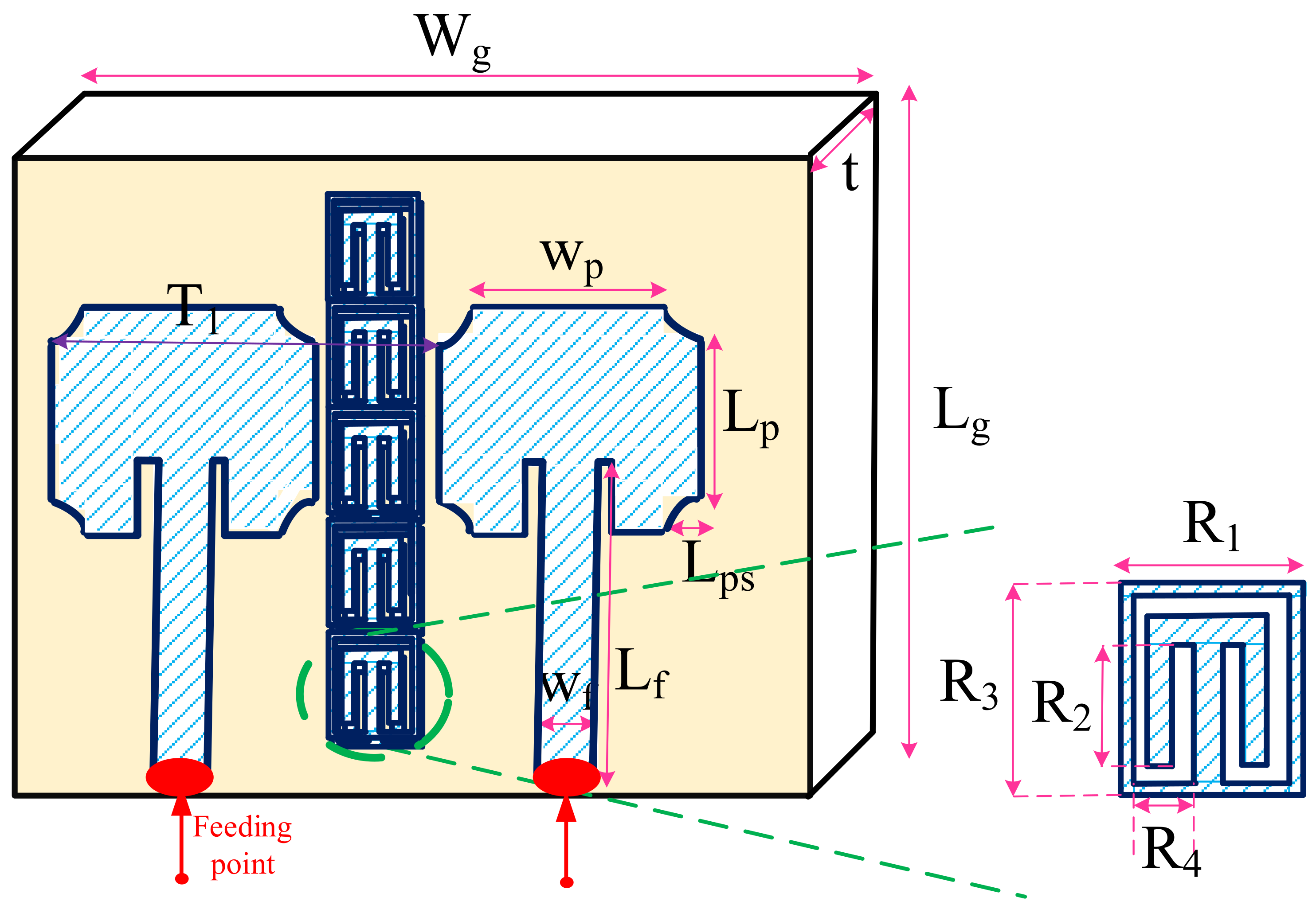
| Design Parameters | Value (mm) | Design Parameters | Value (mm) |
|---|---|---|---|
| 22.5 | 11 | ||
| 8.99 | 1.4 | ||
| 18.1 | 3.2 | ||
| 5.2 | 3.6 | ||
| 6.2 | 1.7 | ||
| 45 | 38 | ||
| 1.65 |
| Design Parameters | Value | Design Parameters | Value |
|---|---|---|---|
| 0.46 | 0.58 | ||
| 0.29 | 1.51 | ||
| 0.64 | 2.72 | ||
| 0.71 | 1.2 | ||
| 0.68 | 0.63 |
| Ref. | Method | Goal(s) of Paper |
|---|---|---|
| [16] | Balancing multiport feeding of the cavity-backed patch antenna | - Providing the optimal loading conditions for doherty PA |
| [17] | PA-aware precoding method by convex optimization | - Exploiting the high-dimensional degrees of freedom; |
| - Enhancing transmission quality | ||
| [18] | Coherent and non-coherent beamforming consideration | - Maximizing the energy efficiency |
| [19] | ANN-based optimization | - Optimizing the radiation and nonlinear performances |
| [20] | Nonlinear loadpull simulations | - Maximizing efficiency and bandwidth |
| [21] | Iterative procedure | - Optimizing radar performance in signal-dependent interference |
| [22] | Analytical expressions for the nonlinear distortion | - Enhancing resource allocation problem |
| [23] | Saleh PA-model for nonlinearity and the large scale satellite channel parameters | - Maximizing the achievable rate of the satellite system |
| [24] | Successive convex approximation | - Considering the capacity of the MIMO channel |
| [25] | Methodology based on the signal-to-noise ratio | - Optimizing energy Efficient |
| This work | Two LSTM-based DNNs with Multivariate Newton’s Method | - Modeling of antenna and amplifier through LSTM-based DNNs; |
| - Predicting the extended impedance over the large bandwidth; | ||
| - Achieving the optimal drain impedances; | ||
| - Enhancing the linearity specification of the overall system. |
Publisher’s Note: MDPI stays neutral with regard to jurisdictional claims in published maps and institutional affiliations. |
© 2022 by the author. Licensee MDPI, Basel, Switzerland. This article is an open access article distributed under the terms and conditions of the Creative Commons Attribution (CC BY) license (https://creativecommons.org/licenses/by/4.0/).
Share and Cite
Kouhalvandi, L. Directly Matching an MMIC Amplifier Integrated with MIMO Antenna through DNNs for Future Networks. Sensors 2022, 22, 7068. https://doi.org/10.3390/s22187068
Kouhalvandi L. Directly Matching an MMIC Amplifier Integrated with MIMO Antenna through DNNs for Future Networks. Sensors. 2022; 22(18):7068. https://doi.org/10.3390/s22187068
Chicago/Turabian StyleKouhalvandi, Lida. 2022. "Directly Matching an MMIC Amplifier Integrated with MIMO Antenna through DNNs for Future Networks" Sensors 22, no. 18: 7068. https://doi.org/10.3390/s22187068
APA StyleKouhalvandi, L. (2022). Directly Matching an MMIC Amplifier Integrated with MIMO Antenna through DNNs for Future Networks. Sensors, 22(18), 7068. https://doi.org/10.3390/s22187068