1. Introduction
According to World Health Organization research [
1], road accidents claim the lives of almost 1.3 million people every year around the world. VANETs offer a viable approach for avoiding such incidents. VANETs are mobile ad hoc networks [
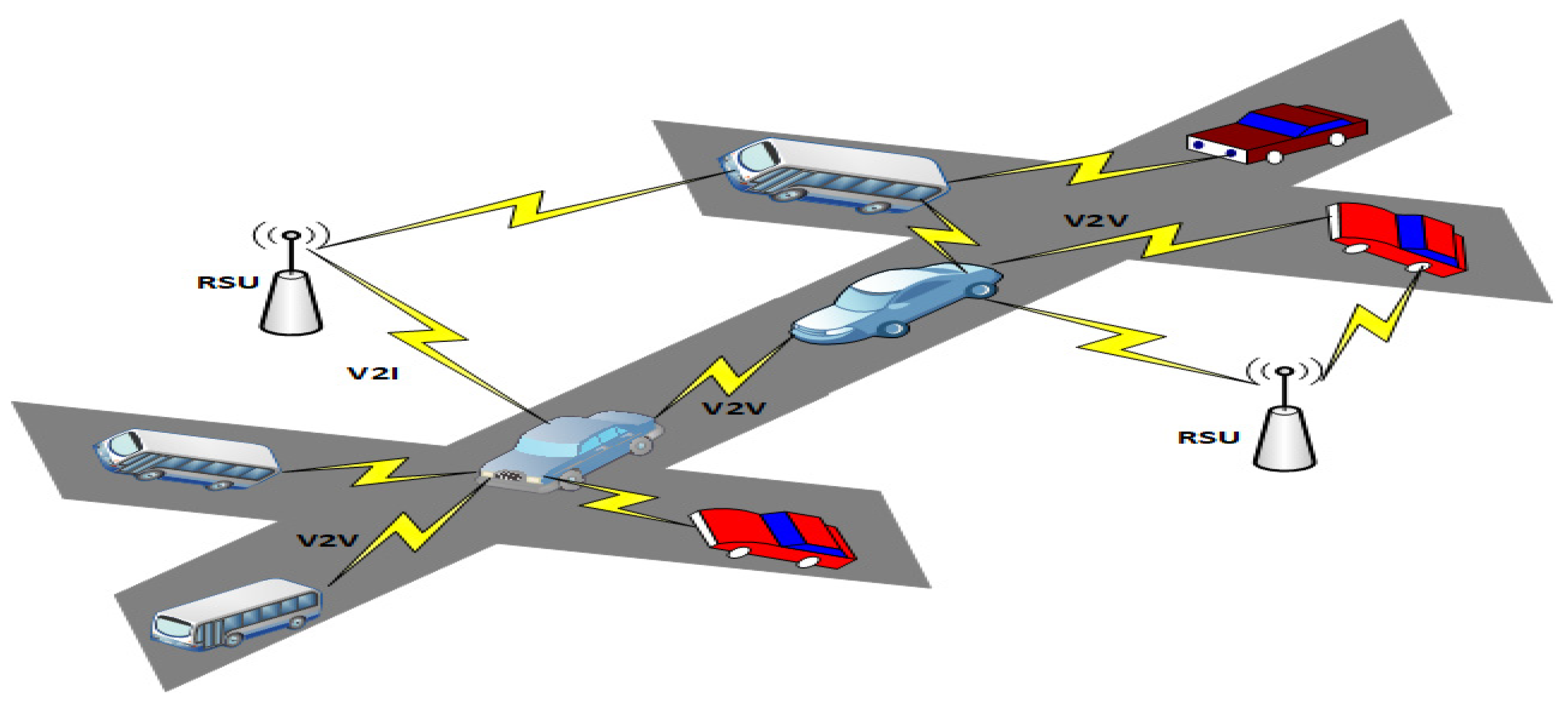
2] that can operate with a diversity of models, such as the Vehicle-to-Infrastructure (V2I) model and Vehicle-to-Vehicle (V2V) model, as depicted in
Figure 1. Advanced communication protocols such as IEEE 802.11p and IEEE 1609 send information between vehicles in the fundamental VANET architecture. VANETs encompass a diverse set of utilizations divided into two categories, i.e., comfort and safety applications. Cooperative collision prevention and traffic updates are examples of safety applications.
In contrast, comfort applications provide value-added services, including entertainment, travel time prediction, path identification, environmental protection, and road conditions [
3]. The prevention of traffic accidents is the most crucial application among these. Safety applications in VANETs mostly rely on warning message (WM) broadcasting. When a vehicle senses a hazardous incident, it transmits WMs to the surrounding vehicles, allowing them to take appropriate action to avoid traffic accidents [
4,
5]. However, on the other hand, unnecessary broadcasting causes several serious problems, including road accidents, redundancy in transmission, and high latency [
6].
Therefore, a rapid and reliable path for WMs is critical, as latency and packet drops during WMs delivery can cause large-scale collisions among vehicles [
6]. When a sender vehicle is ready to send WMs, it may face two scenarios. To begin with, if there is just one path to the target vehicle, it is unavoidable to take that path. Secondly, choosing the optimal route with the least latency and packet drop becomes critical if multiple paths to the target vehicle are available. As a result, selecting the following hop, also known as the optimal forwarder (
Of), is critical during the delivery of WMs.
Greedy routing methods [
7] consider parameters such as the present positions of intermediate relay nodes and their distances from the target node. When vehicles are static, such parameters are valid. In VANETs, the greedy routing protocols [
8] chose the next-hop in a target vehicle direction, which is a good strategy in uni-directional road traffic. However, direction-based greedy protocols’ performances worsen in bi-directional road traffic when a next-hop is picked based on its current location in the direction of the target vehicle. The distances among vehicles change in a bi-directional highway environment because nodes can move at high speeds in both directions. Hence, due to the constant changes in topology, these vehicles leave and enter the transmission ranges with one other regularly. As a result, a path chosen at a specific time step does not remain fixed indefinitely. It may alter at later time-steps somewhat for transmitting even a single warning message. This alteration may happen concerning a decreased or increased number of hops that affect the latency appropriately. Furthermore, paths are broken, and new paths are generated at routine intervals, potentially resulting in network partitions. Therefore, all warning messages routed across the damaged paths are dropped. These aspects lead to high packet losses, delays in WMs transmission, and reduced throughput of the networks.
We present a unique cluster-based approach, OPRP, to disseminate WMs in highway VANETs, addressing the abovementioned difficulties. OPRP considers our mobility parameters when choosing a CH to improve cluster stability and reduce communication overhead. Only a cluster head can disseminate the WMs among its cluster members. Moreover, CH transmits WMs across adjacent cluster heads and increases network efficiency.
Novelty and Contributions
We used a hybrid mechanism to disseminate warning messages. For this, we considered a cluster-based bi-directional highway scenario. The contributions and novelty are as follows:
Dissemination of warning messages has been performed on bi-directional highway roads, but in a non-cluster scenario. The novelty of this paper is the directional-based clustering technique for disseminating warning messages on bi-directional highways.
We propose a modified K-medoids algorithm for selecting cluster heads. To the best of our knowledge, the modified K-medoids have never been used in the literature for cluster head selection in a bi-directional highway scenario. The modified K-medoids algorithm is presented in
Section 3.2.3, Equation (5).
We use the positions and movement directions of the nodes to disseminate warning messages in a clustering-based approach. Previously, either the positions or movement directions of nodes have been used, but not both.
We use the Hamming distance function to find the direction of a node. To the best of our knowledge, Hamming distance has never been used previously in a bi-directional clustering-based approach. It is presented in
Section 3.2.1, Equation (2).
We use Euclidean distance for cluster formation in the bi-directional highway. To the best of our knowledge, this was the first time Euclidean distance was employed for cluster formation in a bi-directional clustering-based approach.
Simulation results reveal that OPRP outperforms renowned WMs dissemination schemes concerning information coverage, end-to-end delay (E2E), network overhead, message reliability, and PDR. The remainder of the paper is organized as follows:
Section 2 reviews related work.
Section 3 offers a system model, and
Section 4 estimates its performance. Finally,
Section 5 presents the conclusion and future work.
2. Related Work
The dissemination of WMs in VANETs has received a lot of interest in recent years. By broadcasting WMs on time, drivers can avoid collisions. As a result, dissemination speed is a vital performance component, particularly for time critical WMs [
9]. Designing such solutions for enormously dynamic vehicle networks is extremely difficult. Therefore, timely WMs transmission and computationally effective solutions are required for WM dissemination in VANETs. The schemes discussed in this subsection address specific WM dissemination issues, such as lowering network overhead and end-to-end delay while boosting information coverage and PDR.
In VANETs, timely and reliable warning messages are as critical as accurate collision detection. For VANETs, several clustering techniques have been suggested. The authors of [
10] presented a clustering technique for VANETs called the Distributed Multichannel and Mobility-Aware Cluster-based MAC Protocol (DMMAC). The DMMAC considers speeding a significant aspect while forming the cluster to improve stability, using a fuzzy framework to measure vehicle speeds. Furthermore, the DMMAC uses a temporary cluster head idea when the original cluster head is unreachable. For every cluster, the protocol chooses a secondary CH. These protocols [
10,
11] are helpful in high-mobility areas, although primary cluster heads frequently change as topologies change. As a result of the frequent switching generated by the primary CH, the secondary cluster head’s efficiency is diminished. Therefore, the clusters become unstable.
Furthermore, the authors of [
12] offered a novel clustering approach that relies on affinity propagation to tackle instability. This technique does not need a constant number of nodes to create a cluster; instead, it employs similarity measurements to transmit messages across data points throughout cluster creation. Although the affinity technique can aid with cluster stability, it does so by involving several iterative loops, which lengthens cluster creation time, and as a result, produces more significant latency.
To achieve effective bandwidth utilization and minimize message delivery time [
13] introduced an event-driven cluster-based method. Furthermore, clustering after event finding produces an end-to-end delay, which is inconvenient for time-crucial information in bi-directional road traffic. The authors of [
14] suggested a clustering strategy called time barrier-based emergency message dissemination in the vehicular ad-hoc network (TBEM) that relies on the time barrier technique and aims to reduce excessive message dissemination. If an event occurs during work, the farthest vehicle is a relay to cover a greater distance. As there are multiple vehicles along the same length of road, numerous vehicles can send the same message, causing network congestion. Furthermore, vehicles are permitted to transmit messages after the time limit expires, resulting in redundancy and affecting network performance.
The authors of [
15] suggested the distributed vehicular broadcast (DV-CAST) protocol to enhance coverage area and eliminate detached network difficulties adaptively. DV-CAST is the only solution we identified in the literature that tackles varying connectivity situations in VANETs. To improve coverage information, DV-CAST uses a store-carry-forward (SCF) method [
16,
17,
18,
19]. Furthermore, the transmitting vehicles send WMs to the farthest vehicle with a high probability of shortening the waiting time. However, when the distance between two vehicles grows, a message’s transmission probability increases linearly. As a result, the SCF method causes end-to-end latency. Multiple vehicles can retransmit the same message in a probabilistic approach, causing network congestion.
The k-medoids [
20] and k-means [
21] algorithms add to the clustering diversity but have similar tendencies. However, a k-medoids algorithm performs better in some cases [
22]. Both algorithms divide the entire sample space into groups of comparable nodes depending on the shortest distance among nodes and a central node, CH. In a k-medoids algorithm, the cluster’s center is always a node, but in a k-means algorithm, it may or may not be. As the mobility of nodes in VANET is high, choosing a geographical place other than the node as the cluster center can induce clustering instability. Furthermore, any approximation made in this direction by choosing the closest node to a central place will reduce accuracy and increase processing overhead. Moreover, compared to a k-means algorithm, a k-medoids algorithm is much more tolerating of outliers [
21].
The study in [
23] presents the fuzzy logic-based technique for creating clusters with long lifetimes. Three parameters are taken into account in this approach. First, it combines node relative speeds with their associated CHs. Second, it examines a node’s number of available links inside a cluster, and third, it considers node security. This method can still be used in uni-directional highway scenarios. In a bi-directional highway scenario, however, selecting member nodes with the same speed as its CHs may be ineffective because they could travel in different directions. This reduces the time it takes for the node to be associated with a cluster. Another similar clustering strategy was proposed in [
24]; however, it lacks the potential to tolerate the variability of bi-directional road traffic. In addition, the authors of [
25] considered connection dependability during clustering. However, this strategy assumes a fixed arrival rate for motorway nodes, which is unsustainable.
The work of [
26] presents a comparative distance-based clustering algorithm that performs poorly in real highway scenarios due to a lack of direction evaluation. Likewise, the authors of [
27] adopted a grey wolf optimization-based clustering method to limit the number of clusters. On the other hand, the approach has a significant computational overhead when identifying weak and aging nodes. One well-known clustering protocol is Low-Energy Adaptive Clustering Hierarchy (LEACH) [
28], which has various multi-hop and single-hop variations. LEACH Fuzzy Inference System (LEACH-FIS) [
29] and Quadrature Low Energy Adaptive Cluster Hierarchy (FCM-QLEACH) [
30] are two current VANET-specific variations. All LEACH techniques are energy-efficient, which is their main advantage, but significant clustering overheads limit their performance.
Similarly, the authors of [
31] presented a clustering technique in which a gateway node is introduced as a relay node between CHs. The gateway node provides the connection between two cluster heads to increase information range without needing roadside units. This scheme is best for uni-directional traffic, and suitable for urban VANETs and unsuitable for highway environments. EEMDS also ignores the node’s direction, degrading the scheme’s performance. The work of RBO-EM [
32] presents a clustering scheme in which the nodes’ numbers are reduced that can retransmit an emergency message, and linked condition reliability is employed to choose a trustworthy gateway. RBO-EM also ignores the node’s direction, degrading the scheme’s performance.
Similarly, the authors of BRUP [
33] presented a network that was hierarchically partitioned into numerous clusters on a roundabout in an urban scenario, each associated with the CH. Only the CH was accountable for the retransmission of WMs in every cluster to avoid redundant transmission and ensure reliable WM dissemination. Furthermore, ref. [
33] employed a k-medoids algorithm for CH selection and Hamming distance for finding a node’s movement direction to maximize the cluster’s lifetime, and it has been proven to operate well in a roundabout in urban settings. BURP does not apply to highways environment where mobility is very high. This paper proposes OPRP as an extension of [
33] to highway environments. The authors of [
1,
34] described message dissemination using SND. However, SDN separates the data and control plane, and the controller should interact with the underlying network to have a global view of the status of the data plane. Hence, when there are dynamic changes in the network, there should be a frequent status update in the SDN controller.
When there is a new packet for which the flow rules do not exist in the underlying switches, it must be sent to the controller, and the same applies for the updated status. Consequently, it adds delay. Moreover, when the algorithm for dissemination runs and the new updates rules are found, those rules must be pushed to the flow tables of the SDN switches. Hence, there will be an additional flow setup delay.
Table 1 shows a comparison of several WM dissemination techniques.
3. Proposed Protocol
This section proposes our protocol (OPRP) enabling V2V communication betwixt nodes traveling in the real-time bi-directional highway environment. The timely propagation of WMs is crucial in VANET environments, necessitating an effective routing mechanism. In the following subsection, we propose the system model for bi-directional highway VANETs. CH selection, WM distribution, and dynamic cluster formation are all included in the proposed approach.
3.1. System Model
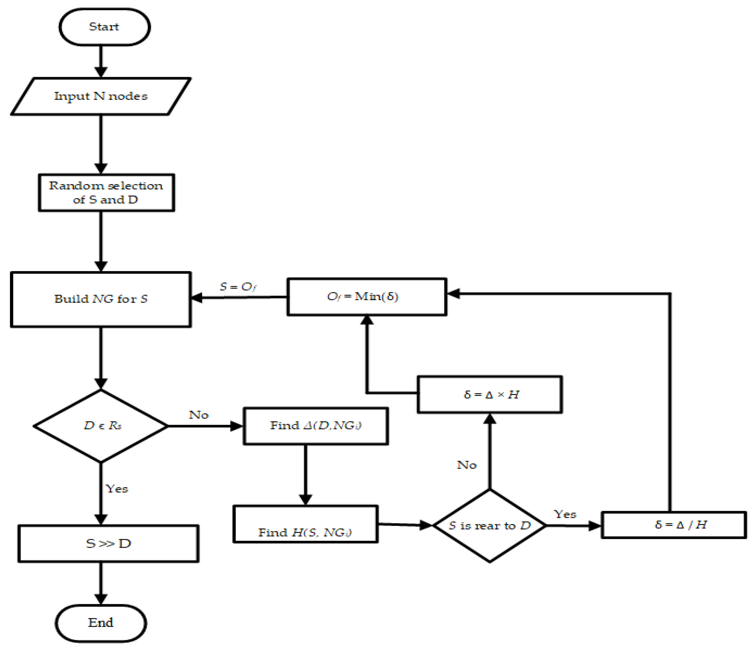
Figure 2 depicts a detailed outline of the proposed protocol, which achieves direction-based priority assignments among numerous routes to a destination. Collisions among nodes on a wide scale could be caused by an ineffective routing strategy for vehicle collision prevention. As a result, routing performance becomes equally essential in addition to the importance of node collision detection. Delivering timely and reliable WMs is crucial for implementing collision-prevention procedures. Once a source node is willing to send a WM, and there is only one path to the destination, following that path becomes unavoidable. When there are numerous paths to the target, choosing the optimum path with the least latency, the fewest packet losses, and the highest throughput becomes critical. Greedy protocols use distance as a parameter to find the optimum path, whereas direction-based Greedy protocols look for available relay nodes in the direction of the destination node. All paths to the target are examined for a specified time step, such as τ0. However, the node’s mobility is very high; they regularly enter and exit each other’s communication ranges, resulting in continual topological changes in bi-direction circumstances. Due to this dynamic nature, two scenarios may arise during message delivery.
Firstly, paths to the target may encounter outages, causing all communications transmitted on these paths to be lost. Second, because the path specified at τ0 does not always stay intact, it may go through a path reconstruction phase at τ1, τ2, …, τn until a message is successfully delivered.
This might be increasing or decreasing the length of a path. As a result, the rate of packet drops and delays increase, reducing the throughput of the Greedy and direction-based Greedy protocols. Therefore, in complement to a distance parameter, we recommend using the following parameters for the optimum path selection:
The direction of node movement: here, we apply Equation (1) to find the direction of a node’s movement.
The source and destination nodes’ relative positions.
The list of notations used in this research can also be found in
Table 2. In this regard, the proposed protocol includes two phases: the cluster formation phase and the optimal path discovery phase. The subsections below go over all of these phases in detail.
3.2. Cluster Formation Phase
The following assumptions are taken into account by OPRP:
Each node starts in a safe state, with no probability of crashing.
Each node has the on-board unit (OBU) for communication and a Global Positioning System (GPS) for positioning.
Each node can determine its direction, speed, location, and deceleration or acceleration.
Each node may calculate its maximum average radio range based on its surroundings, which can be utilized to connect and communicate with the other nodes.
Ordinary vehicles (OV) and CHs are the two types of nodes that the suggested OPRP applies to. A CH is in charge of the cluster and keeps a record of all nodes that make up the cluster. An OV represents a non-CH member node. A CH constructs a list of each of its member nodes, which includes current location, current speed, node-id, expected state, and acceleration/deceleration. The following are possible states for a node:
The node moves forward from a standstill to enter the highway. In this circumstance, it will either join an established cluster or establish its cluster.
The node maintains the same direction and speed on the highway. In this situation, it continues to move with the same cluster. During the travels, its speed may alter as it accelerates or decelerates with time, resulting in a change in its cluster.
While moving with the highway, a node may reverse its heading and begin moving in the opposite direction. This will result in a cluster change for this particular node.
This subsection of the suggested OPRP describes cluster creation, including how nodes can find their neighbors and enter or depart a cluster. The k-medoids algorithm is possibly a better option for clustering based on the benefits stated in the previous section. The simple k-medoids approach, on the other hand, is insufficient for clustering bi-directional road traffic. The direction parameter is considered to accommodate bi-directional road traffic. To that end, in the suggested OPRP, we present a variation to the fundamental k-medoids algorithm and employ the modified form for clustering. The rest of this section explains the various phases required in clustering in a bi-directional environment using the revised k-medoids algorithm.
3.2.1. Neighbor Discovery
We offer Algorithm 1, which takes
Ack and
N as inputs and finds neighbors, where
N = n1, n2, …, nx denotes a set of all nodes, and
Ack denotes an acknowledgment received in response to a transmitted Hello packet. Here,
n denotes a single member node, and x represents the number of nodes on the path. The algorithm discovers neighbor nodes and creates a neighboring table (
NG), which is a list of all of a node’s neighbors. Neighbors are nodes connected directly to one another or within one hop. Each node broadcasts Hello packets at regular intervals to discover its neighbors.
| Algorithm1: Neighbor Discovery. |
| Input: Ack,N |
| Output: NG |
- 1.
Begin: - 2.
Flush NGs - 3.
i←0 - 4.
S broadcast Hello packets - 5.
Repeat: - 6.
for Ack received from node ni - 7.
S updates the NGs - 8.
NGs (i, 1)←NIDni - 9.
NGs (i, 2)←CNPni - 10.
NGs (i, 3)←𝜏ni - 11.
incrementi - 12.
until: All the received Acks are processed or each cluster - 13.
Return NG - 14.
end
|
When S obtains an Ack from another node in reply to its broadcasted Hello packet, it adds this node to its NG. In NG, information about nearby nodes is maintained in the form of current node position (CNP), node identity (NID), and the time stamp (𝜏) of the last correctly received Ack. Here, 𝜏 is used to determine the freshness of the received Ack packet and to remove any older information. For node localization, we suppose every node is fitted with a Global Positioning System (GPS). Algorithm 1 produces NG as a result. The algorithm’s complexity is on average Θ(n). The output of the algorithm is NG for the neighbors at each time period.
3.2.2. Node Joining a Cluster
When different nodes come in, a highway becomes crowded with clusters. The highway’s first node forms its cluster and deputizes itself as a CH. The CH is re-selected for every cluster when the number of nodes within cluster grows, as explained in
Section 3.2.3. A candidate node, a node that wants to join the cluster, sends out a Hello message. The OVs ignore this communication, but all CHs in the vicinity acknowledge it.
The number of acknowledgments a candidate node receives is the number of available clusters (k) for the k-medoids algorithm. The distance betwixt this candidate node and every CH is calculated when the position information is shared. The nearest CH is found, so this applicant node joins that cluster to which it belongs. Suppose a candidate node cannot find a cluster—i.e., it receives no acknowledgment in reply to a Hello message. The candidate node builds its cluster and deputizes itself as the CH.
The main k-medoids algorithm [
20] uses Manhattan distance for clustering. In contrast, the modified k-medoids algorithm presented in this paper for OPRP employs two metrics, Euclidean distance, and Hamming distance, to create clusters. The first metric, Euclidean distance, calculates the distance between a candidate node and all of the CHs nearby. Hence,
where
η denotes the Euclidean distance calculated between the CHs and applicant node with coordinates (
,
) and (
,
), respectively.
The Hamming distance function, which includes the bi-directional aspect of a road traffic flow, is the next metric computed after the Euclidean distance. The nodes on the highway can move in opposite directions because the bi-directional heterogeneous traffic allows it. Hamming distance function calculates in light of the difference in travel directions between an applicant node and a CH. The result is 1 if a candidate node and the CH have the same direction and 0 if they have the opposite direction [
33]; i.e.,
here, the Hamming distance is denoted by κ, and the direction is represented by regardless of the node type (i.e., OV or CH).
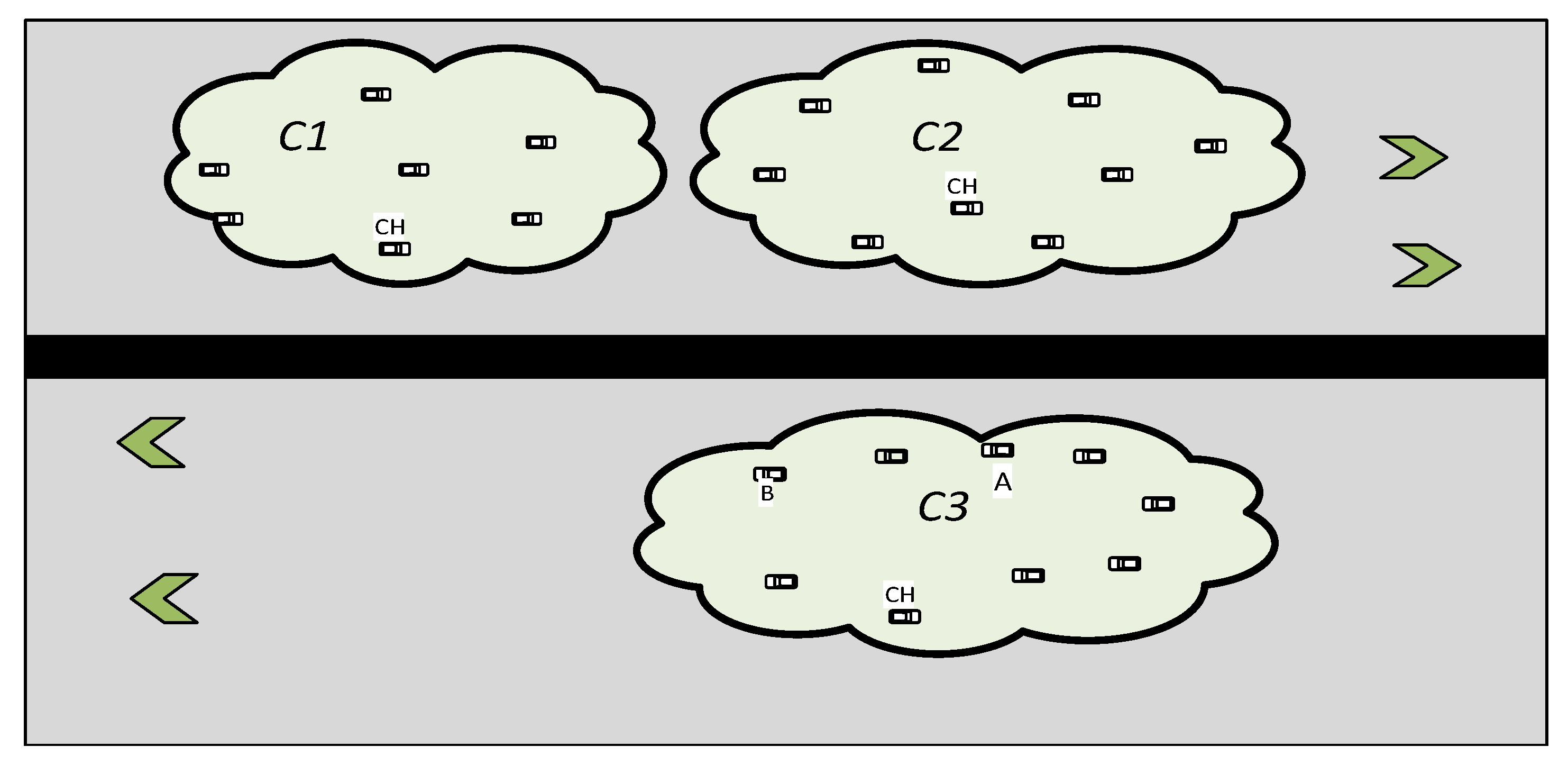
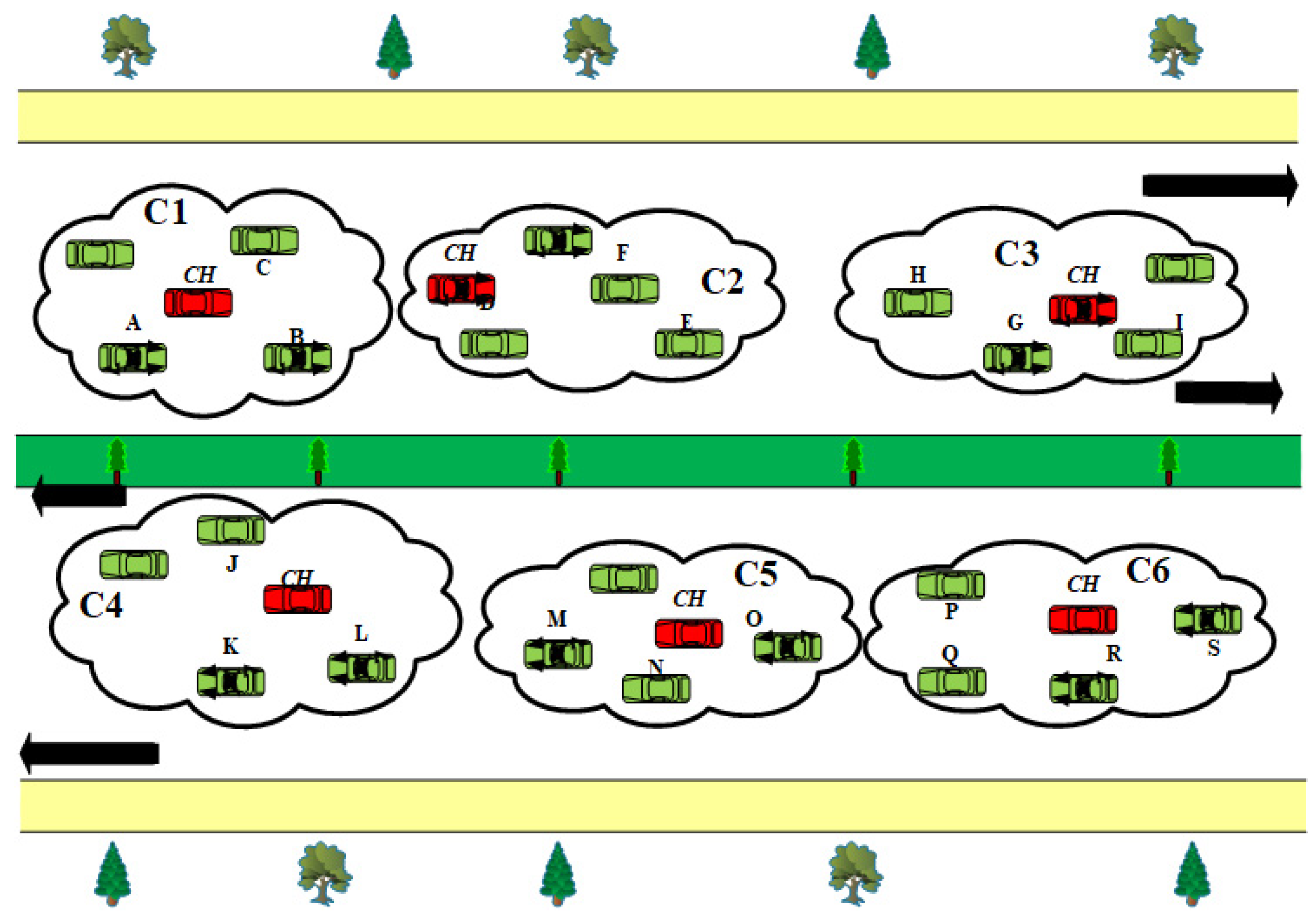
It is essential to rely on the two metrics described above when connecting nodes to a cluster. Assume, for instance, that Node A is located 3 m from C2: CH and 4 m from C3: CH in
Figure 3. This node will connect to C2 using simply the distance factor. This should not occur, since Node A and the members of C2 are traveling in opposing directions, and Node A joining C2 would destabilize the cluster rather than serve a proper function. OPRP suggests Equation (3) to solve this problem, which determines the ultimate distance by adding the directional components and relative components. By applying this criterion, the distance between Node A and C2: CH increases to infinity while the distance between Node A and C3: CH stays at 4 m. As a result, Node A will join C3. As a result, by associating the node with the cluster in the same direction, a node equation used in a modified k-medoids algorithm for OPRP favorably and efficiently contributes to the definition of stable clusters. Hence,
where
δ stands for the relative distance between two adjacent nodes.
The distance with all neighboring CHs is calculated by Equation (3) because OPRP considers the attachment of the candidate node to the cluster upon the shortest distance from the appropriate CH. Additionally, Equation (4) locates a CH with the smallest distance and links the node to the relevant cluster, converting that candidate node’s position to that of the member node. Thus,
where
is the minimum distance
CH,
represents the
ith candidate node, and
CHi is the
ith cluster in the sample space.
Using our modified k-medoids technique, Algorithm 2 outlines how a node might join a specific cluster. The inputs for this algorithm are
k,
M, and
S.
k is the number of the clusters obtained in response to a Hello message,
M is the set of CHs, and
S is the set of applicant nodes. The algorithm’s output consists of
k clusters created or modified by adding
N nodes, where
N stands for the collection of member nodes in the cluster. The algorithm’s complexity is on average Θ(n). The output of the algorithm is
K clusters each time.
| Algorithm2: Candidate Node Joining a Cluster. |
| Input: K, M, S |
| Output: K cluster with N nodes |
- 1.
Begin: - 2.
repeat: - 3.
if K ≠ 0 then - 4.
for each member of M do - 5.
Compute ηi using (1) - 6.
Compute κi using (2) - 7.
Compute δi using (3) - 8.
Ti ⇐ δi - 9.
CHmin ⇐ Min [T] using (4) - 10.
CHmin ← Si - 11.
Nmin ← Si - 12.
endfor - 13.
else - 14.
K ⇐ K + 1 - 15.
CHi ← Si - 16.
Mi ← CHi - 17.
endif - 18.
until: All the members of S are clustered - 19.
end
|
3.2.3. Cluster Head Selection
The CH node in our suggested approach is the one that is the closest to every other node in the cluster. It is reducing the number of hops lowers communication latency. As seen in
Figure 2, the CH selection procedure continues to iterate until the clusters merge. This convergence is best attained if no modification is seen after two iterations [
20]. When a first potential node enters a highway and forms its own cluster, as was covered in the previous subsection, the CH is chosen. The modified k-medoids algorithm determines the median of each cluster when the clusters are filled with nodes. Therefore, this median, also known as the medoid, computed using Equation (5), is elected as the new CH for a cluster [
33]. Thus,
where
Mc represents the set of CHs and n is the number of nodes in a cluster.
The suggested k-medoids approach in Algorithm 3 provides phases for choosing a CH in a particular cluster.
K and
N are the inputs for Algorithm 3. This algorithm’s output includes
Mc. The algorithm’s complexity is on average Θ(n). The algorithm’s outcome is an
Mc set of the cluster heads each time.
| Algorithm3: Cluster Head Selection. |
| Input: K, N |
| Output: M |
- 1.
Begin: - 2.
repeat: - 3.
if N = 1 then - 4.
CHi← Ni - 5.
Mi← CHi - 6.
else if N > 2 then - 7.
CHi ← median (N) using (5) - 8.
Mi← CHi - 9.
endif - 10.
until: CH is selected for K clusters - 11.
end
|
3.2.4. Node Leaving a Cluster
The OPRP offers a planned method for member nodes to leave a cluster. This results from a member node changing its path or accelerating or decelerating. The nodes most likely to leave a cluster are edge nodes, which are found close to their boundaries. Even when the node is not an edge node, it transforms into one shortly before leaving. Every member node in OPRP maintains a threshold, ε, to keep itself connected to a specific cluster. When a node wants to leave its cluster, this threshold is evaluated concerning an immediate neighbor node. Once this threshold is reached, the member node communicates a leaving message to its CH, indicating that it is willing to leave the cluster. The CH announces its departure and deletes any entries related to that node from its list. OPRP suggests updating ε as follows for a node that wants to leave its cluster:
where Δ represents a fading component and
μ is the node’s transmission range that contributes to the definition of
ε for a node in terms of
μ. As soon as a leaving node reaches the fading area, also known as
μ −
ε, which is located around the boundaries of a given node’s communication range, the leaving node begins to leave the associated cluster. Depending on the circumstances, the departing node may join another cluster or form its own cluster.
Algorithm 4 offers instructions for removing a node from a specific cluster, utilizing our improved k-medoids algorithm. If the departing node is a CH, it specifies the CH re-election criteria. In that algorithm, Nr stands for the randomly chosen node, which is chosen as a temporary CH upon an existing CH’s departure from its cluster. This method takes the inputs K and N, and its output is a notification of Ni’s departure. The algorithm’s complexity is on average Θ(n). The algorithm’s output is the Ni node leaving a notification each time.
| Algorithm 4: Node Leaving. |
| Input:K, N |
| Output: Leaving notification of Ni |
- 1.
Begin: - 2.
repeat: - 3.
if K ≠ φ then - 4.
if η(Ni, Ni+1) > ε or η(Ni, Ni−1) > ε then - 5.
if Ni ≡ CHi then - 6.
CHi ← Ni - 7.
perform CH selection - 8.
else - 9.
CHi → Ni - 10.
endif - 11.
endif - 12.
endif - 13.
endrepeat - 14.
End
|
3.2.5. CH Re-Selection
It is also feasible that the leaving node is the CH when considering the earlier standard for node exit from a cluster. In this scenario, the CH temporarily hands over to
Nr, a node selected at random, gathering data on all of the member nodes and conducting CH election similarly to
Section 3.2.3.
5. Performance Evaluation
The effectiveness of our suggested OPRP procedure is assessed in this section concerning DABFS [
8] and ID-LAR [
7]. We employed the Mobility Model Generator for Vehicular Networks (MOVE) [
35], Simulation of Urban Mobility (SUMO) [
36], and ns-2.35 to assess performance in a realistic vehicular environment. Route information, intersections, and node positions were produced by SUMO and MOVE and used by ns-2.35. Unless otherwise stated, all simulations were based on Scenarios 1 to 5, depicted in
Figure 4 in
Section 4. The performance evaluation parameters for the protocols mentioned above are listed in
Table 3. Nodes with omni-directional antennas are dispersed at random. The nodes were moving bi-directional at varying rates belonging to a set, χ, with lower and upper bounds of 0 m/s and 42 m/s, respectively. The acceleration or deceleration that nodes achieved was in the range of 1 to 6 m/s
2. In addition,
Table 4 shows the number of nodes on the highway was categorized as sparse, medium, or dense. This classification adjusts the node density by actual traffic [
37].
Throughput (Tr), packet loss rate (Pr), and end-to-end delay (Er), which are frequently used metrics in state-of-the-art to analyze VANET routing protocols for efficient distribution of WMs with minimal latencies and few packet losses, were among the efficiency evaluation measures [
38,
39].
Figure 5,
Figure 6 and
Figure 7 illustrate the simulation results for each metric. The
Figure 7a–e in each figure correspond to the five different scenarios presented in Scenarios 1 through 5 of
Section 4.2.
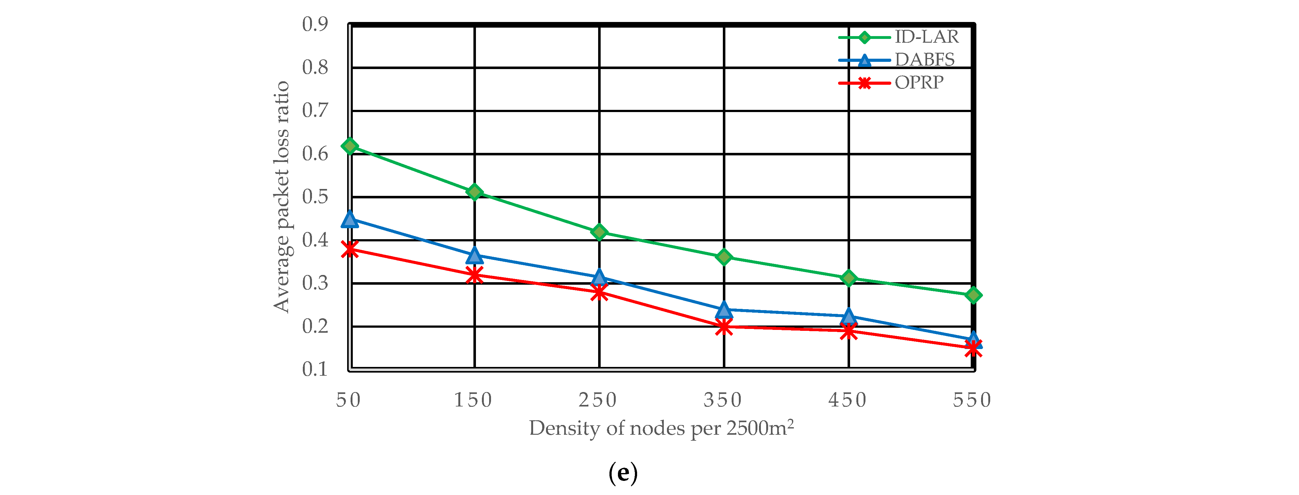
5.1. Packet Loss Rate
This parameter is the ratio of dropped packets, which may be calculated as follows:
where
Pr denotes the packet loss rate,
Pli is a dropped packet, and
Pt is the total number of packets delivered across the network.
Due to the repeated network changes, the path choice during WM transmission remains crucial. In VANETs, topological changes are frequently caused by fast nodes traveling in various directions. The nodes continuously move, enter, and exit each other’s communication ranges. As a result, paths are frequently dropped and new ones generated, potentially leading to network partitions. As a greater number of nodes enhances network connectivity and lowers packet drops, the probability of such network partitioning seems higher in scatter networks than in dense networks. The packet loss ratio decreases as the density increases because nodes are closer. Hence, the proposed protocol with clustering and the compared protocols without clustering becomes more intimate in the results. The three protocols’ results illustrated in
Figure 5a–e reveal such behavior.
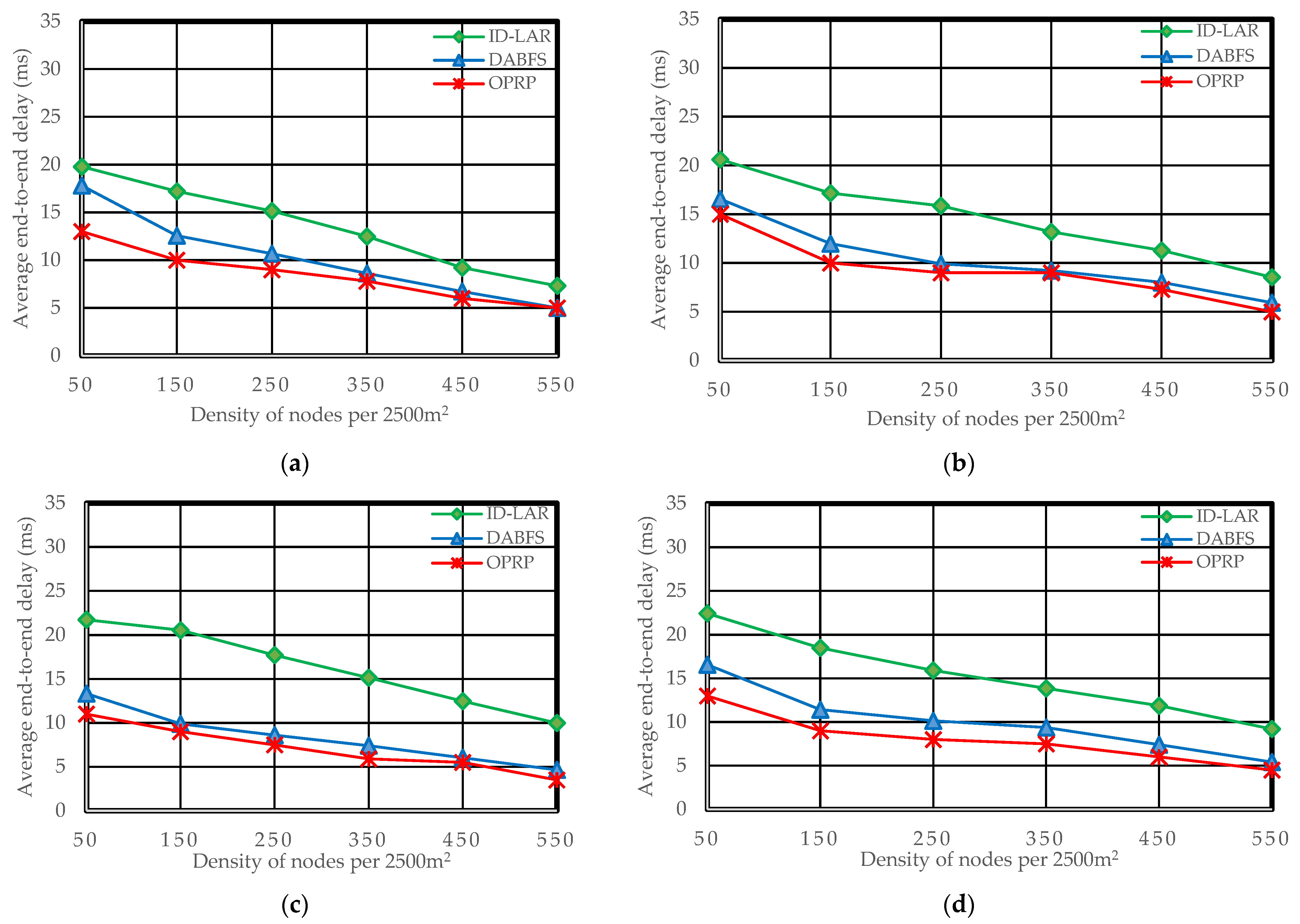
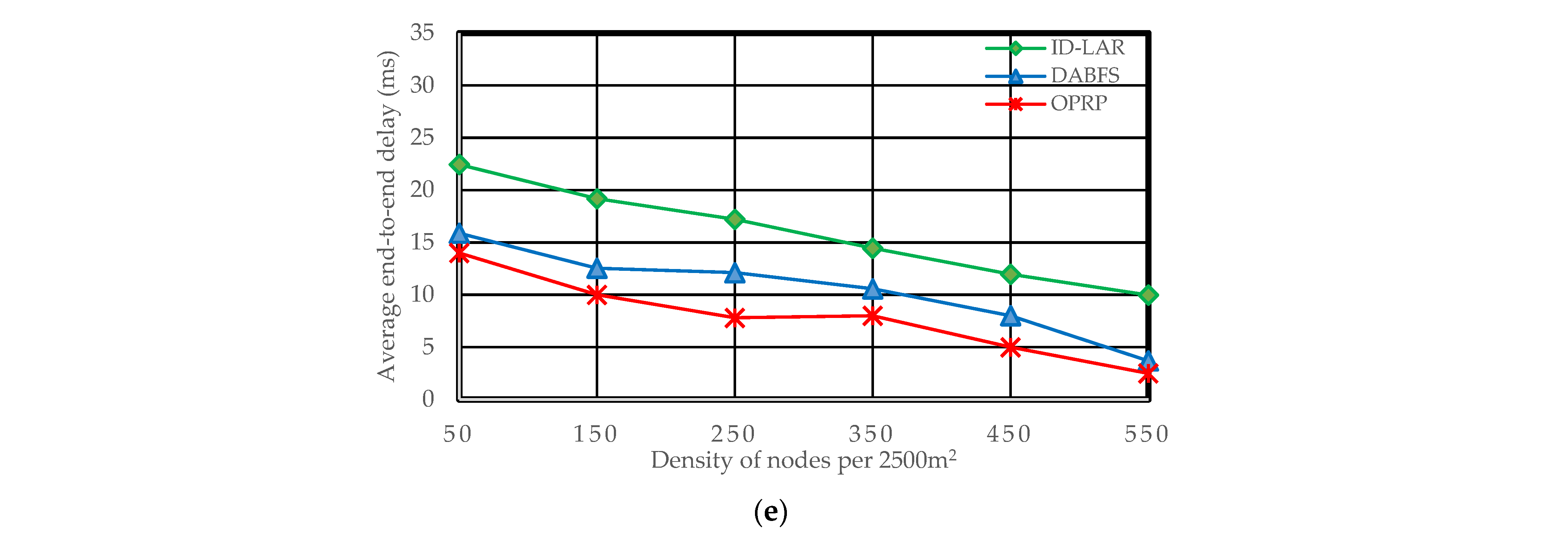
5.2. End-to-End Delay
End-to-end delays can be computed as:
where the terms
Er and
Edi and
Rp stand for the end-to-end delay ratio, the individual packet delay, and the total number of packets received. Due to the increased number of hops in DABFS and ID-LAR, as a result of the path reconstruction process, as detailed in
Section 4.2.1, the total number of send and receive operations also increases. The efficiency of both DABFS and ID-LAR is negatively impacted by the growing number of transmitting and receive operations because they are time-consuming. However, by choosing the next hops traveling in the target node’s direction, OPRP reduces this latency. The end-to-end delay decreases as the density increases because nodes are closer. Hence, the proposed protocol with clustering and the compared protocols without clustering become clearer in the results.
Figure 6a–e reveals Scenario 5.
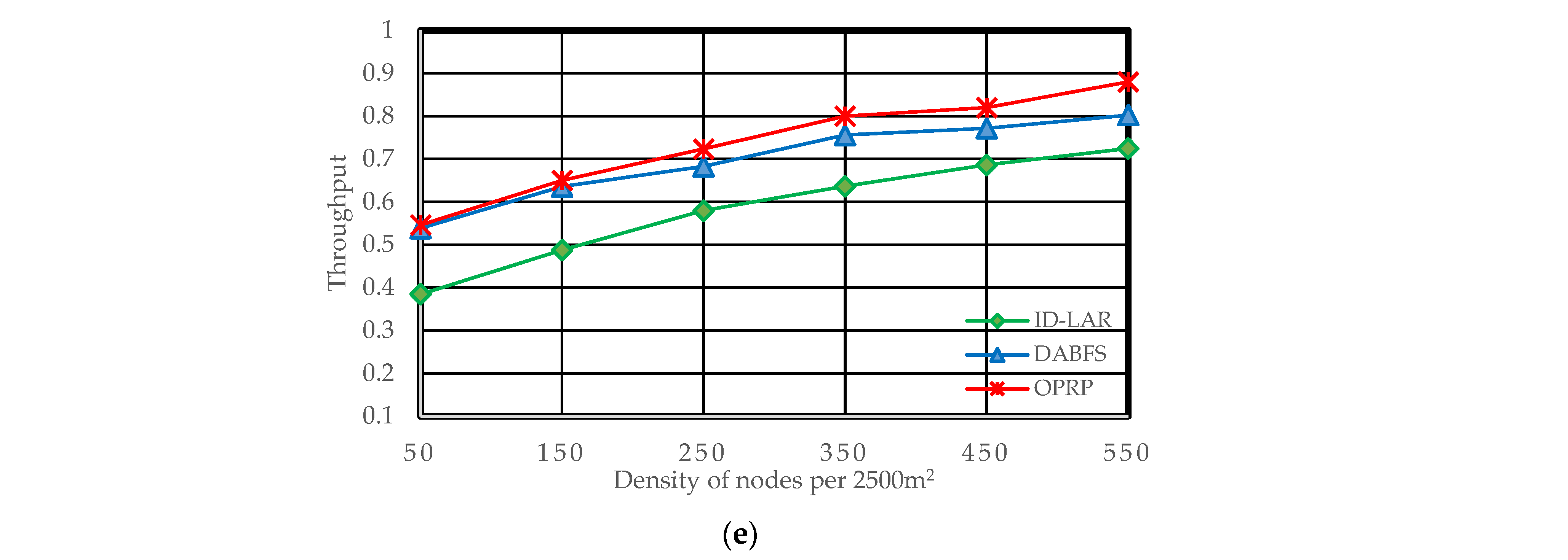
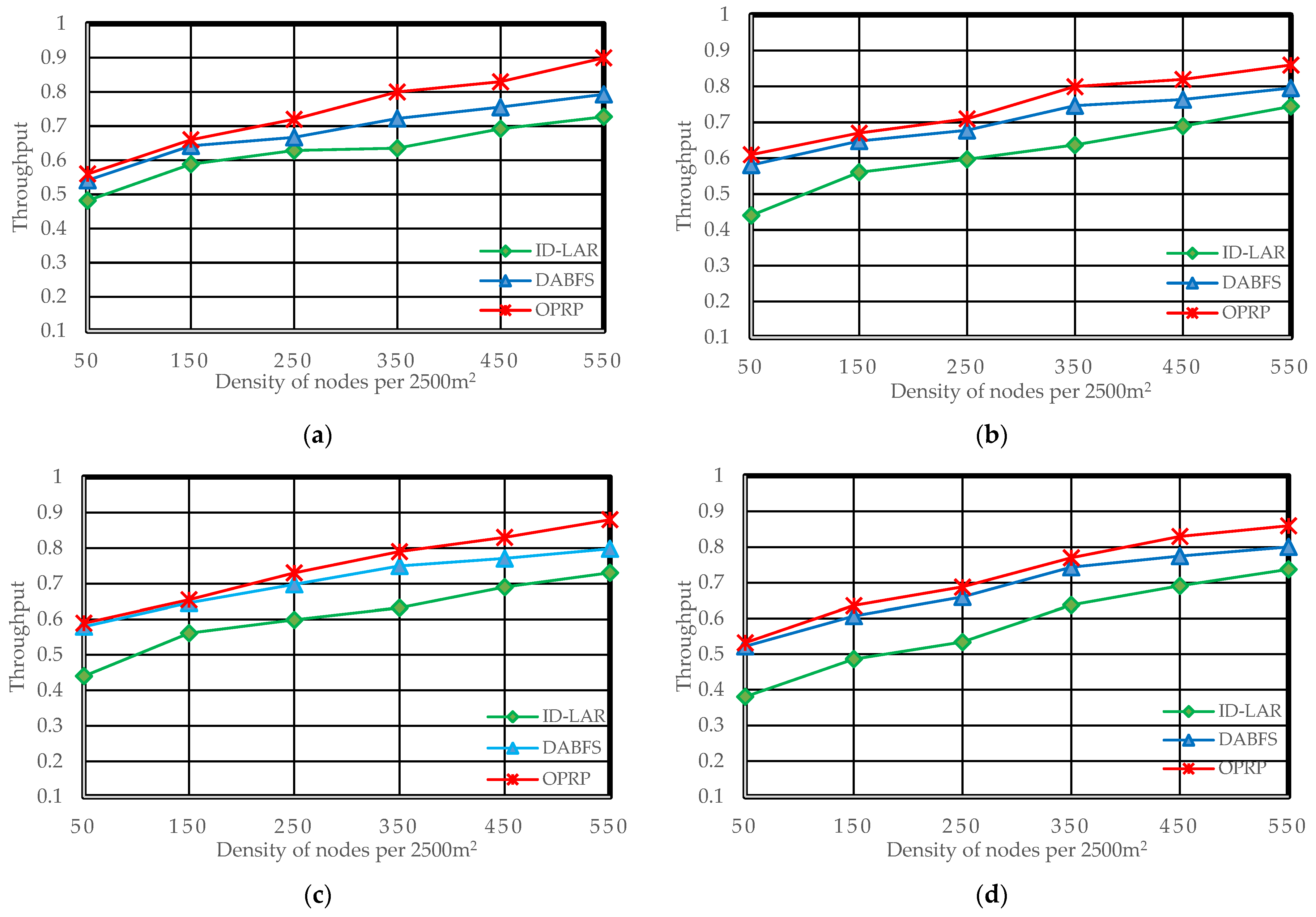
5.3. Throughput
This parameter, which can be calculated, refers to the proportion of packets received on the destination nodes of all packages sent by the source nodes.
where
refers to the network throughput gain,
refers to the total number of packets sent by the source node, and
denotes a specific packet received by a target node.
As it counts the number of packets successfully delivered to target nodes, throughput is a crucial metric for performance evaluation. End-to-end delays and packet losses impact the throughput of the network.
Figure 7a,b show improved throughput of OPRP compared to DABFS and ID-LAR due to our original direction-based path selection. Additionally, OPRP follows the same pattern under challenging circumstances where the source and destination are on the opposite sides of the road by significantly improving throughput, as demonstrated in
Figure 7c,d. Additionally, as shown in
Figure 7e, OPRP outperformed the other protocols, improving throughput restoration state packet forwarding.
Moreover, the packet loss ratio and end-to-end delay decrease as the density increases because nodes are closer. As a result, the throughput increases. Therefore, the proposed protocol with clustering and the compared protocols without clustering are clearly illustrated in the results.


 ,
, 


