
A Novel Grayscale Image Encryption Scheme Based on the Block-Level Swapping of Pixels and the Chaotic System


 , ,
, ,  , and
, and
Abstract
:1. Introduction
- The scheme is efficient regarding the computational time. Thus, it has good chances for its real-world application.
- This scheme has achieved better throughput. Moreover, the incorporation of plaintext sensitivity is a good way to avert the potential threats of cryptanalytic attacks.
- The majority of instructions of the suggested scheme are repetitive. Thus this scheme can be easily customized to run in some parallel settings.
2. Basic Principles
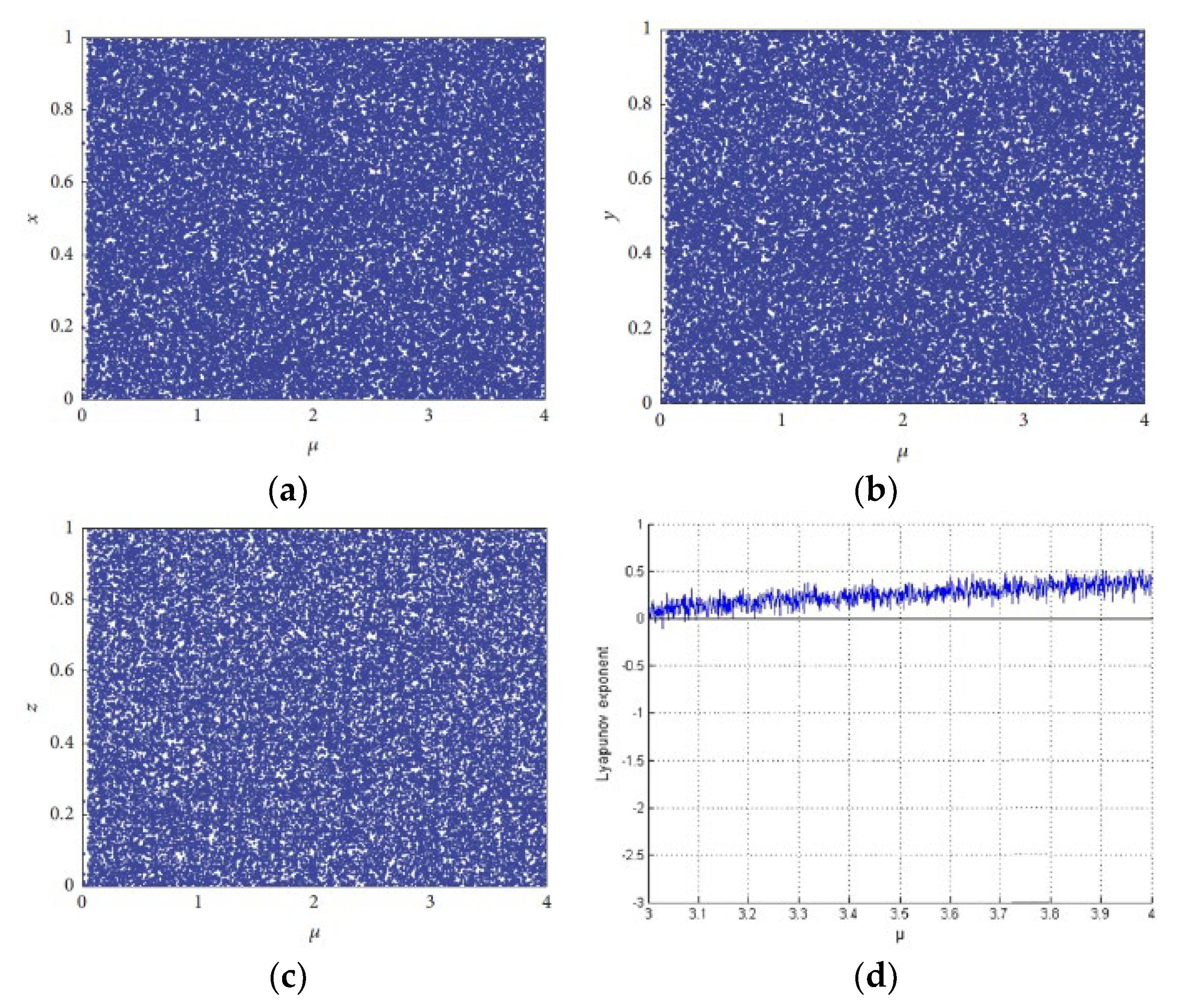
2.1. Chaotic System
2.2. Block Swapping
3. Proposed Block-Based Image Encryption Scheme
3.1. Generation of the Initial Values and System Parameters
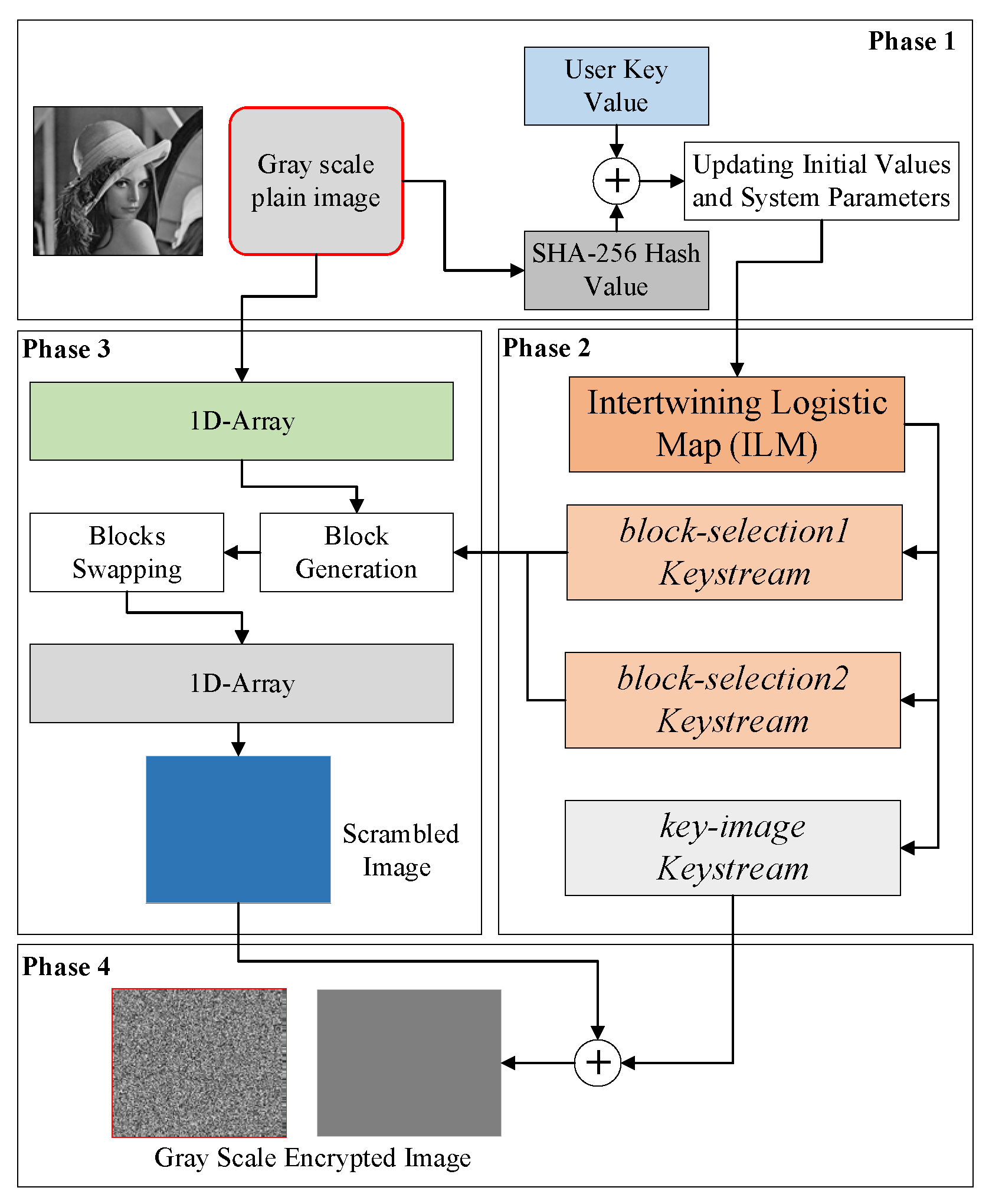
3.2. Encryption Procedure
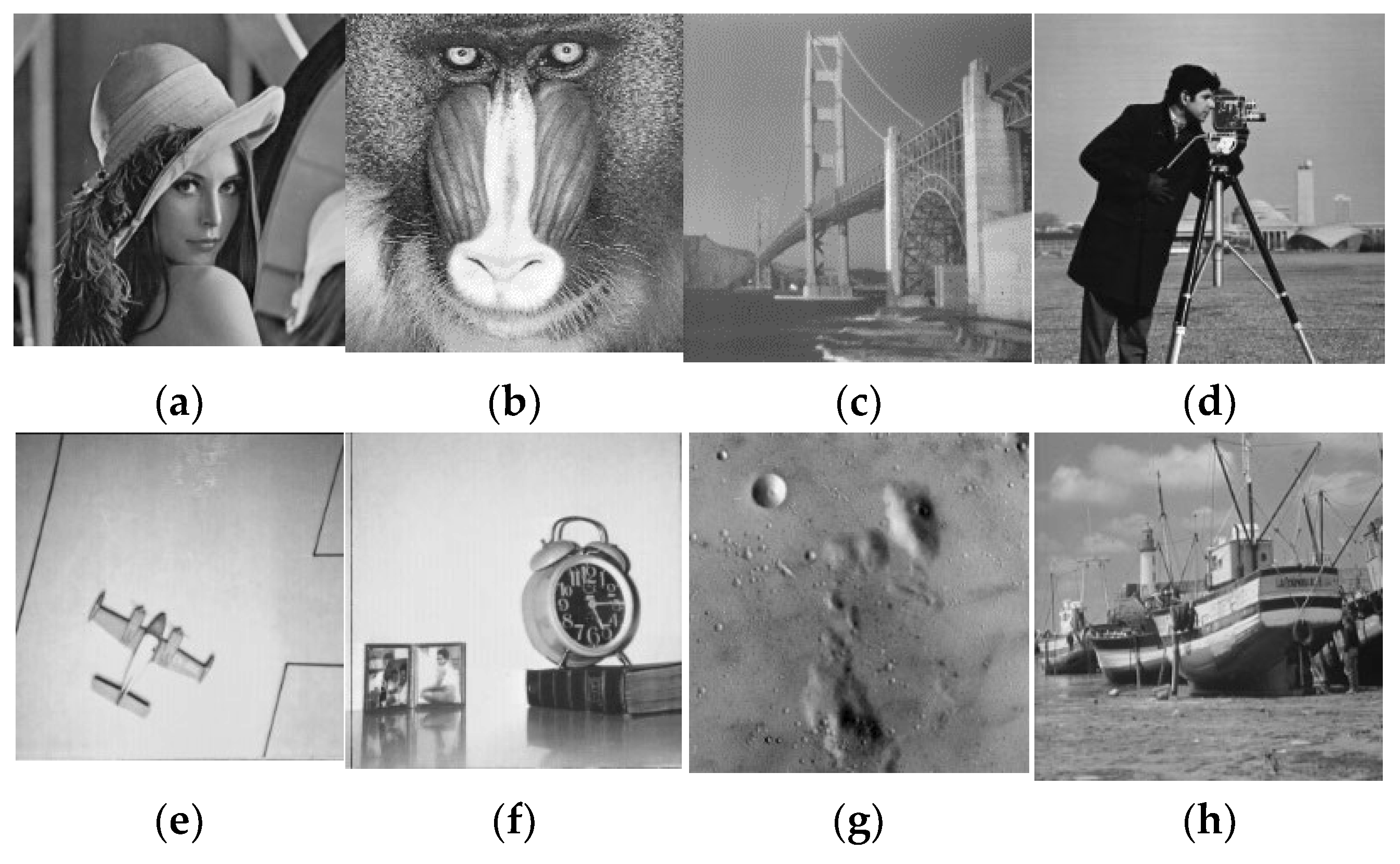
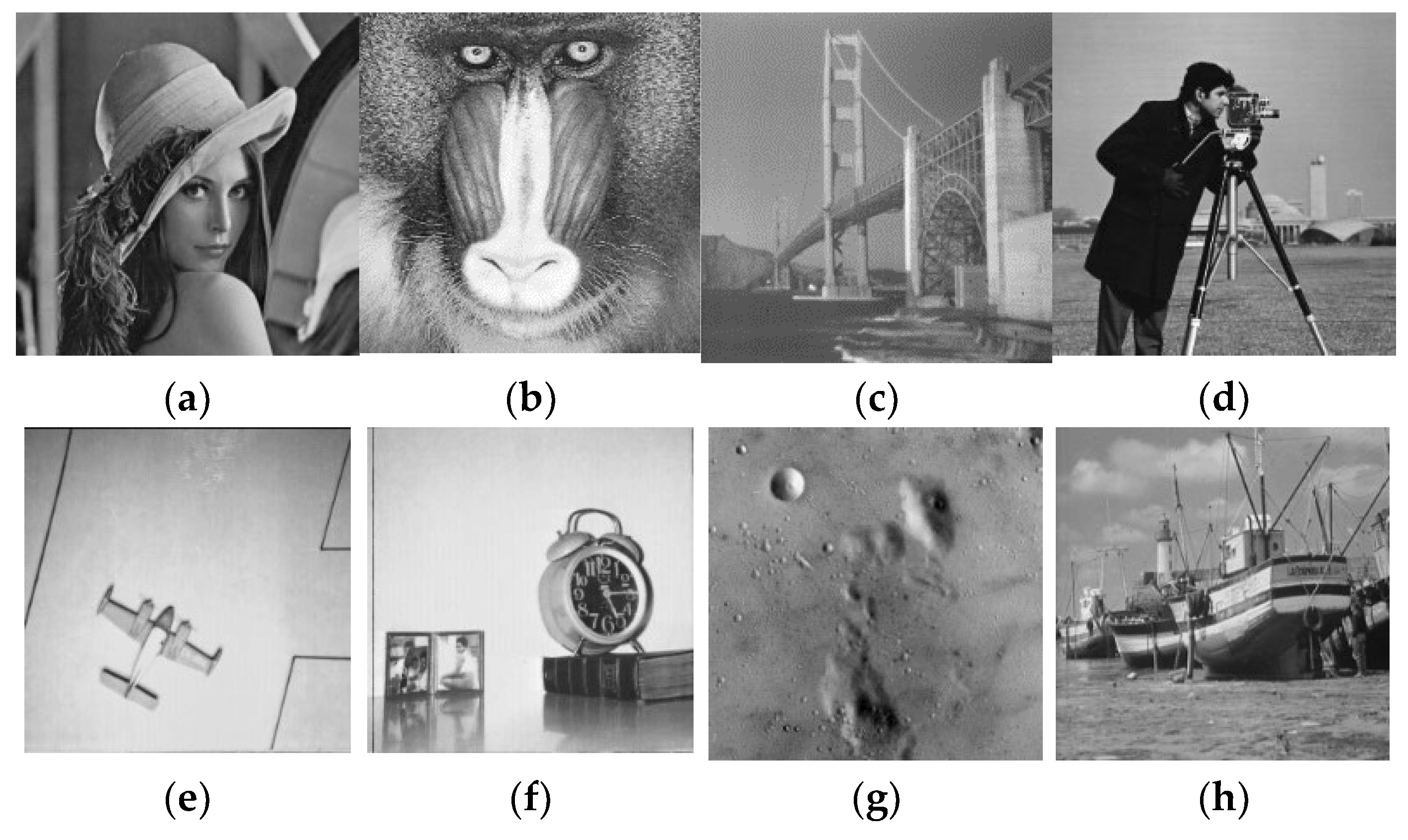
4. Simulation
5. Security Analysis
5.1. Key Space Analysis
5.2. Statistical Analysis
5.2.1. Histogram Analysis
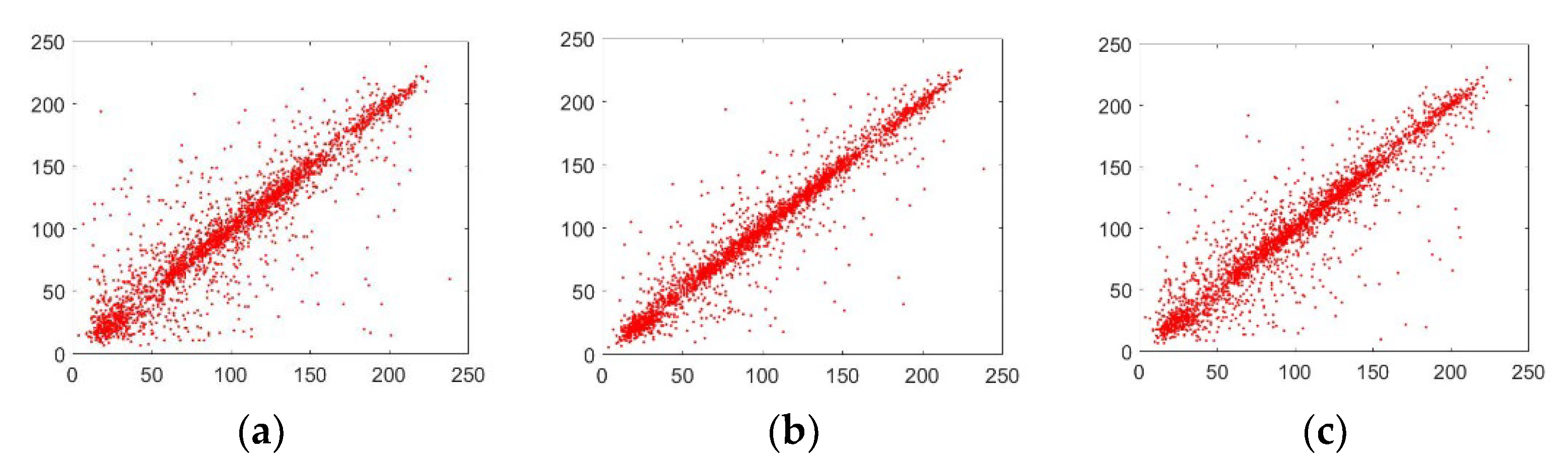
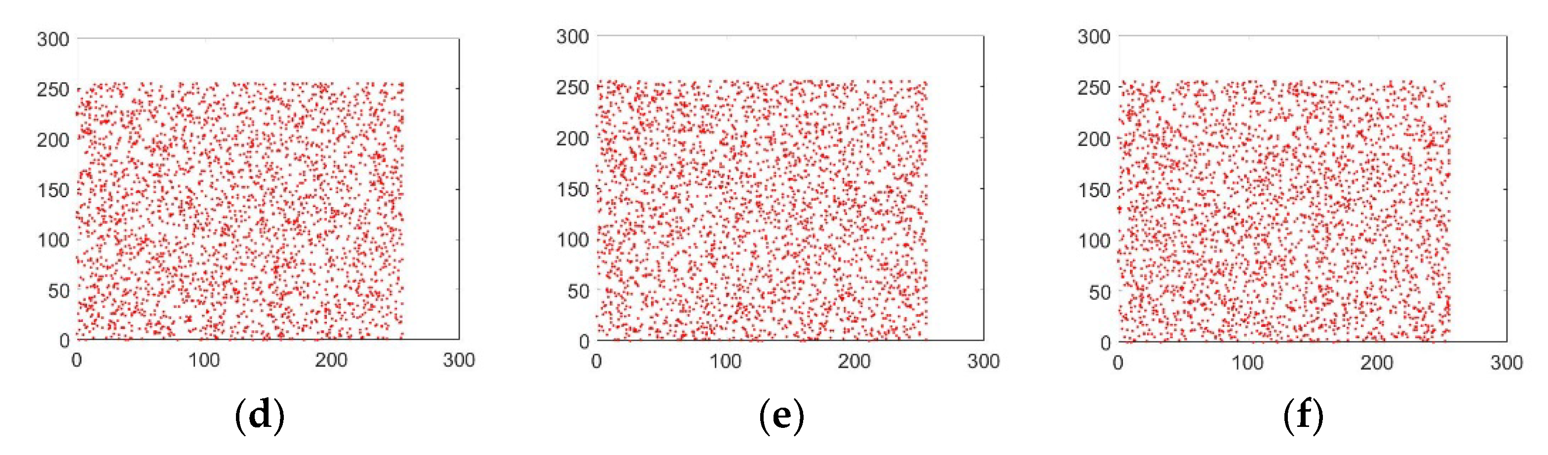
5.2.2. Analysis of the Correlation Coefficient
5.3. Analysis of Information Entropy
5.4. Plaintext Sensitivity Analysis (Differential Attack)
5.5. Peak Signal-to-Noise Ratio (PSNR) Analysis
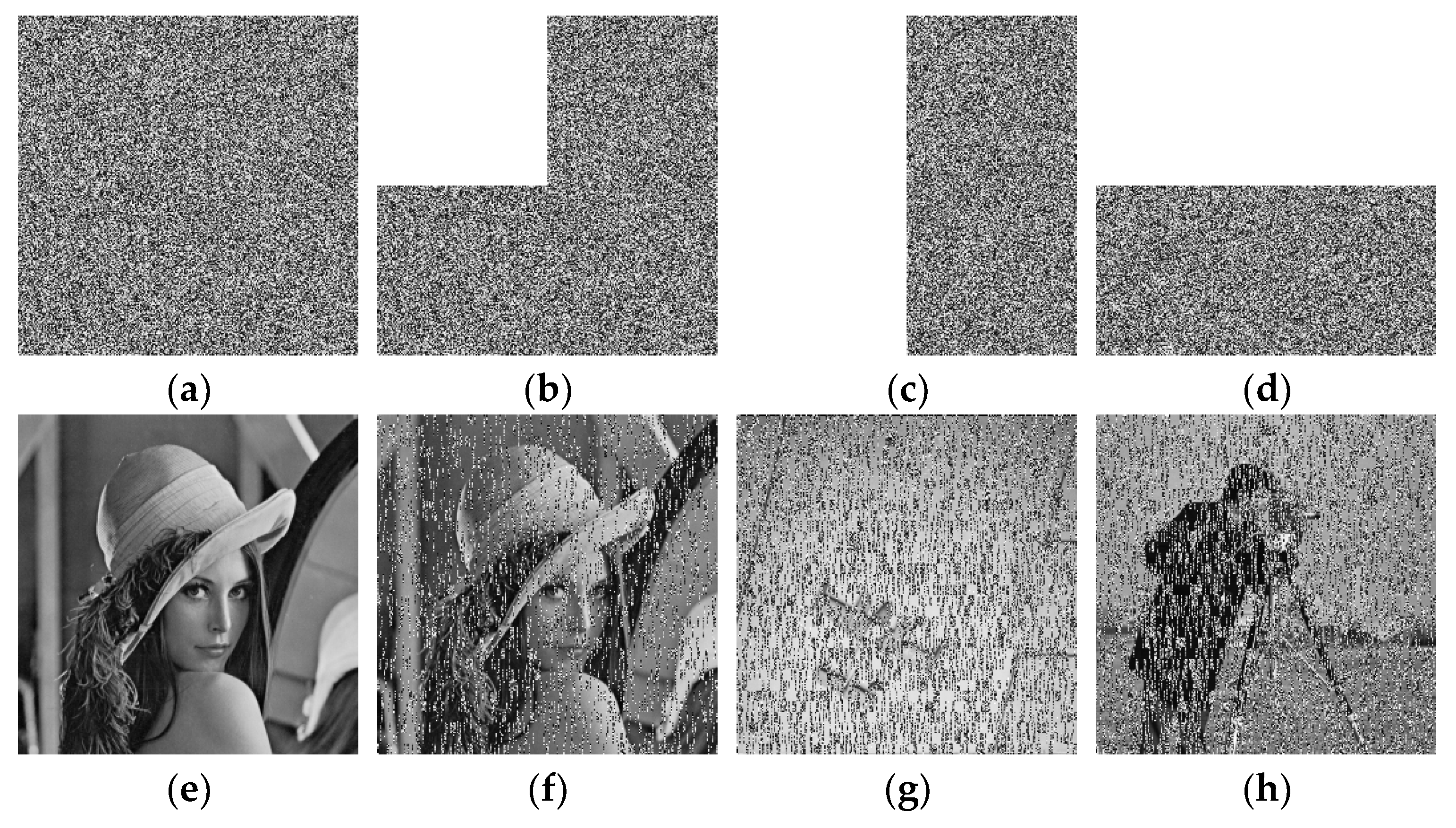
5.6. Noise and Data Loss Analysis
5.7. Computational Time Analysis
6. Conclusions
Author Contributions
Funding
Institutional Review Board Statement
Informed Consent Statement
Data Availability Statement
Conflicts of Interest
References
- Bashir, Z.; Iqbal, N.; Hanif, M. A novel gray scale image encryption scheme based on pixels’ swapping operations. Multimed. Tools Appl. 2020, 80, 1029–1054. [Google Scholar] [CrossRef]
- Wan, Y.; Wang, S.; Du, B. A bit plane image encryption algorithm based on compound chaos. Multimed. Tools Appl. 2022, in press. [CrossRef]
- Zheng, J.; Zeng, Q. An image encryption algorithm using a dynamic S-box and chaotic maps. Appl. Intell. 2022, in press. [CrossRef]
- Sharkawy, N.H.; Afify, Y.M.; Gad, W.; Badr, N. Gray-Scale Image Encryption Using DNA Operations. IEEE Access 2022, 10, 63004–63019. [Google Scholar] [CrossRef]
- Tanveer, M.; Shah, T.; Rehman, A.; Ali, A.; Siddiqui, G.F.; Saba, T.; Tariq, U. Multi-Images Encryption Scheme Based on 3D Chaotic Map and Substitution Box. IEEE Access 2021, 9, 73924–73937. [Google Scholar] [CrossRef]
- Mirzaei, O.; Yaghoobi, M.; Irani, H. A new image encryption method: Parallel sub-image encryption with hyper chaos. Nonlinear Dyn. 2011, 67, 557–566. [Google Scholar] [CrossRef]
- Patro, K.A.K.; Soni, A.; Netam, P.K.; Acharya, B. Multiple grayscale image encryption using cross-coupled chaotic maps. J. Inf. Secur. Appl. 2020, 52, 102470. [Google Scholar] [CrossRef]
- Iqbal, N.; Abbas, S.; Khan, M.A.; Fatima, A.; Ahmed, A.; Anwer, N. Efficient image cipher based on the movement of king on the chessboard and chaotic system. J. Electron. Imaging 2020, 29, 023025. [Google Scholar] [CrossRef]
- Girdhar, A.; Kapur, H.; Kumar, V. A novel grayscale image encryption approach based on chaotic maps and image blocks. Appl. Phys. A 2021, 127, 1–12. [Google Scholar] [CrossRef]
- Chowdhary, C.L.; Patel, P.V.; Kathrotia, K.J.; Attique, M.; Perumal, K.; Ijaz, M.F. Analytical Study of Hybrid Techniques for Image Encryption and Decryption. Sensors 2020, 20, 5162. [Google Scholar] [CrossRef]
- Hanif, M.; Abbas, S.; Khan, M.A.; Iqbal, N.; Rehman, Z.U.; Saeed, M.A.; Mohamed, E.M. A Novel and Efficient Multiple RGB Images Cipher Based on Chaotic System and Circular Shift Operations. IEEE Access 2020, 8, 146408–146427. [Google Scholar] [CrossRef]
- Iqbal, N.; Hanif, M.; Abbas, S.; Khan, M.A.; Rehman, Z.U. Dynamic 3D scrambled image based RGB image encryption scheme using hyperchaotic system and DNA encoding. J. Inf. Secur. Appl. 2021, 58, 102809. [Google Scholar] [CrossRef]
- Xu, Q.; Sun, K.; Cao, C.; Zhu, C. A fast image encryption algorithm based on compressive sensing and hyperchaotic map. Opt. Lasers Eng. 2019, 121, 203–214. [Google Scholar] [CrossRef]
- Hasheminejad, A.; Rostami, M. A novel bit level multiphase algorithm for image encryption based on PWLCM chaotic map. Optik 2019, 184, 205–213. [Google Scholar] [CrossRef]
- Wu, T.; Xie, S.-C.; Zhang, J.-Z.; Zhao, H.-X. Color image encryption algorithm based on the position index and chaos theory. J. Electron. Imaging 2019, 28, 53008. [Google Scholar] [CrossRef]
- Iqbal, N.; Abbas, S.; Khan, M.A.; Alyas, T.; Fatima, A.; Ahmad, A. An RGB Image Cipher Using Chaotic Systems, 15-Puzzle Problem and DNA Computing. IEEE Access 2019, 7, 174051–174071. [Google Scholar] [CrossRef]
- Shao, Z.; Liu, X.; Yao, Q.; Qi, N.; Shang, Y.; Zhang, J. Multiple-image encryption based on chaotic phase mask and equal modulus decomposition in quaternion gyrator domain. Signal Process. Image Commun. 2019, 80, 115662. [Google Scholar] [CrossRef]
- Girdhar, A.; Kumar, V. A RGB image encryption technique using Lorenz and Rossler chaotic system on DNA sequences. Multimed. Tools Appl. 2018, 77, 27017–27039. [Google Scholar] [CrossRef]
- Iqbal, N.; Hanif, M.; Abbas, S.; Khan, M.A.; Almotiri, S.H.; Al Ghamdi, M.A. DNA Strands Level Scrambling Based Color Image Encryption Scheme. IEEE Access 2020, 8, 178167–178182. [Google Scholar] [CrossRef]
- Zhang, X.; Wang, X. Multiple-image encryption algorithm based on mixed image element and chaos. Comput. Electr. Eng. 2017, 62, 401–413. [Google Scholar] [CrossRef]
- Chai, X.; Chen, Y.; Broyde, L. A novel chaos-based image encryption algorithm using DNA sequence operations. Opt. Lasers Eng. 2017, 88, 197–213. [Google Scholar] [CrossRef]
- Suri, S.; Vijay, R. A synchronous intertwining logistic map-DNA approach for color image encryption. J. Ambient Intell. Humaniz. Comput. 2018, 10, 2277–2290. [Google Scholar] [CrossRef]
- Enayatifar, R.; Abdullah, A.H.; Isnin, I.F.; Altameem, A.; Lee, M. Image encryption using a synchronous permutation-diffusion technique. Opt. Lasers Eng. 2017, 90, 146–154. [Google Scholar] [CrossRef]
- Cao, C.; Sun, K.; Liu, W. A novel bit-level image encryption algorithm based on 2D-LICM hyperchaotic map. Signal Process. 2018, 143, 122–133. [Google Scholar] [CrossRef]
- Patro, K.A.K.; Acharya, B. A novel multi-dimensional multiple image encryption technique. Multimed. Tools Appl. 2020, 79, 12959–12994. [Google Scholar] [CrossRef]
- Wang, X.; Xu, D. A novel image encryption scheme using chaos and Langton’s Ant cellular automaton. Nonlinear Dyn. 2014, 79, 2449–2456. [Google Scholar] [CrossRef]
- Li, S.; Li, C.; Chen, G.; Zhang, D.; Bourbakis, N. A General Cryptanalysis of Permutation-Only Multimedia Encryption Algorithms. IACR’s Cryptology ePrint Archive. 2015, pp. 1–20. Available online: http://citeseerx.ist.psu.edu/viewdoc/download?doi=10.1.1.59.449&rep=rep1&type=pdf (accessed on 2 January 2022).
- Li, C.; Lo, K.-T. Optimal quantitative cryptanalysis of permutation-only multimedia ciphers against plaintext attacks. Signal Process. 2011, 91, 949–954. [Google Scholar] [CrossRef]
- Özkaynak, F.; Ozer, A.B. Cryptanalysis of a new image encryption algorithm based on chaos. Optik 2016, 127, 5190–5192. [Google Scholar] [CrossRef]
- Zhang, W.; Wong, K.-W.; Yu, H.; Zhu, Z.-L. A symmetric color image encryption algorithm using the intrinsic features of bit distributions. Commun. Nonlinear Sci. Numer. Simul. 2013, 18, 584–600. [Google Scholar] [CrossRef]
- Zhang, W.; Yu, H.; Zhao, Y.-L.; Zhu, Z.-L. Image encryption based on three-dimensional bit matrix permutation. Signal Process. 2016, 118, 36–50. [Google Scholar] [CrossRef]
- Hua, Z.; Zhou, Y.; Pun, C.-M.; Chen, C.P. 2D Sine Logistic modulation map for image encryption. Inf. Sci. 2014, 297, 80–94. [Google Scholar] [CrossRef]
- Chen, L.; Ma, B.; Zhao, X.; Wang, S. Differential cryptanalysis of a novel image encryption algorithm based on chaos and Line map. Nonlinear Dyn. 2016, 87, 1797–1807. [Google Scholar] [CrossRef]
- Hoang, T.M.; Thanh, H.X. Cryptanalysis and security improvement for a symmetric color image encryption algorithm. Optik 2018, 155, 366–383. [Google Scholar] [CrossRef]
- Wu, J.; Liao, X.; Yang, B. Cryptanalysis and enhancements of image encryption based on three-dimensional bit matrix permutation. Signal Process. 2018, 142, 292–300. [Google Scholar] [CrossRef]
- Zhou, Y.; Bao, L.; Chen, C.P. A new 1D chaotic system for image encryption. Signal Process. 2013, 97, 172–182. [Google Scholar] [CrossRef]
- Khan, M. A novel image encryption scheme based on multiple chaotic S-boxes. Nonlinear Dyn. 2015, 82, 527–533. [Google Scholar] [CrossRef]
- Patro, K.A.K.; Acharya, B. Secure multi–level permutation operation based multiple colour image encryption. J. Inf. Secur. Appl. 2018, 40, 111–133. [Google Scholar] [CrossRef]
- Bano, A.; Singh, P. Image encryption using block based transformation algorithm. Pharma Innov. J. 2019, 8, 11–18. [Google Scholar]
- Artiles, J.A.; Chaves, D.P.; Pimentel, C. Image encryption using block cipher and chaotic sequences. Signal Process. Image Commun. 2019, 79, 24–31. [Google Scholar] [CrossRef]
- Liu, X.; Xiao, D.; Huang, W.; Liu, C. Quantum Block Image Encryption Based on Arnold Transform and Sine Chaotification Model. IEEE Access 2019, 7, 57188–57199. [Google Scholar] [CrossRef]
- Ramasamy, P.; Ranganathan, V.; Kadry, S.; Damaševičius, R.; Blažauskas, T. An image encryption scheme based on block scrambling, modified zigzag transformation and key generation using enhanced logistic—Tent map. Entropy 2019, 21, 656. [Google Scholar] [CrossRef]
- Xu, L.; Gou, X.; Li, Z.; Li, J. A novel chaotic image encryption algorithm using block scrambling and dynamic index based diffusion. Opt. Lasers Eng. 2017, 91, 41–52. [Google Scholar] [CrossRef]
- Zhu, S.; Zhu, C. Plaintext-Related Image Encryption Algorithm Based on Block Structure and Five-Dimensional Chaotic Map. IEEE Access 2019, 7, 147106–147118. [Google Scholar] [CrossRef]
- Chai, X.-L.; Gan, Z.; Zhang, M. A fast chaos-based image encryption scheme with a novel plain image-related swapping block permutation and block diffusion. Multimed. Tools Appl. 2016, 76, 15561–15585. [Google Scholar] [CrossRef]
- Wang, X.; Liu, L.; Zhang, Y. A novel chaotic block image encryption algorithm based on dynamic random growth technique. Opt. Lasers Eng. 2015, 66, 10–18. [Google Scholar] [CrossRef]
- Ye, G. A block image encryption algorithm based on wave transmission and chaotic systems. Nonlinear Dyn. 2013, 75, 417–427. [Google Scholar] [CrossRef]
- Chai, X.; Gan, Z.; Yang, K.; Chen, Y.; Liu, X. An image encryption algorithm based on the memristive hyperchaotic system, cellular automata and DNA sequence operations. Signal Process. Image Commun. 2017, 52, 6–19. [Google Scholar] [CrossRef]
- Khan, M.A.; Ahmad, J.; Javaid, Q.; Saqib, N.A. An efficient and secure partial image encryption for wireless multimedia sensor networks using discrete wavelet transform, chaotic maps and substitution box. J. Mod. Opt. 2017, 64, 531–540. [Google Scholar] [CrossRef]
- IEEE Computer Society Standards Committee. IEEE Standard for Binary Floating-Point Arithmetic; IEEE: Piscataway, NJ, USA, 1985; Volume 754. [Google Scholar]
- Ye, R.; Xi, Y.; Ma, Y. A chaotic image encryption scheme using swapping based confusion approach. In Proceedings of the 2016 First IEEE International Conference on Computer Communication and the Internet (ICCCI), Wuhan, China, 13–15 October 2016; pp. 374–377. [Google Scholar] [CrossRef]
- Fu, C.; Zhao, G.-Y.; Gao, M.; Ma, H.-F. A chaotic symmetric image cipher using a pixel-swapping based permutation. In Proceedings of the 2013 IEEE International Conference of IEEE Region 10 (TENCON 2013), Xi’an, China, 22–25 October 2013; pp. 1–6. [Google Scholar] [CrossRef]
- Chen, J.-X.; Zhu, Z.-L.; Fu, C.; Yu, H. An improved permutation-diffusion type image cipher with a chaotic orbit perturbing mechanism. Opt. Express 2013, 21, 27873–27890. [Google Scholar] [CrossRef]
- Chen, J.-X.; Zhu, Z.-L.; Fu, C.; Yu, H. A fast image encryption scheme with a novel pixel swapping-based confusion approach. Nonlinear Dyn. 2014, 77, 1191–1207. [Google Scholar] [CrossRef]
- Shannon, C.E. Communication Theory of Secrecy Systems. Bell Syst. Technol. J. 1949, 28, 656–715. [Google Scholar] [CrossRef]
- Parvees, M.Y.M.; Samath, J.A.; Bose, B.P. Secured Medical Images—A Chaotic Pixel Scrambling Approach. J. Med. Syst. 2016, 40, 1–11. [Google Scholar] [CrossRef] [PubMed]
- Wong, K.-W.; Kwok, B.S.-H.; Yuen, C.-H. An efficient diffusion approach for chaos-based image encryption. Chaos Solitons Fractals 2009, 41, 2652–2663. [Google Scholar] [CrossRef]
- Zhu, C. A novel image encryption scheme based on improved hyperchaotic sequences. Opt. Commun. 2012, 285, 29–37. [Google Scholar] [CrossRef]
- Norouzi, B.; Mirzakuchaki, S. A fast color image encryption algorithm based on hyper-chaotic systems. Nonlinear Dyn. 2014, 78, 995–1015. [Google Scholar] [CrossRef]
- Taneja, N.; Raman, B.; Gupta, I. Combinational domain encryption for still visual data. Multimed. Tools Appl. 2011, 59, 775–793. [Google Scholar] [CrossRef]
- Rehman, A.U.; Liao, X.; Kulsoom, A.; Ullah, S. A modified (Dual) fusion technique for image encryption using SHA-256 hash and multiple chaotic maps. Multimed. Tools Appl. 2015, 75, 11241–11266. [Google Scholar] [CrossRef]
- Hu, T.; Liu, Y.; Gong, L.-H.; Guo, S.-F.; Yuan, H.-M. Chaotic image cryptosystem using DNA deletion and DNA insertion. Signal Process. 2017, 134, 234–243. [Google Scholar] [CrossRef]
- Chai, X.; Fu, X.; Gan, Z.; Lu, Y.; Chen, Y. A color image cryptosystem based on dynamic DNA encryption and chaos. Signal Process. 2018, 155, 44–62. [Google Scholar] [CrossRef]


| Algorithm | Key Space |
|---|---|
| Ours | 1.16 × 10182 |
| [19] | 10105 |
| [45] | |
| [51] | 10128 |
| [52] | 1090 |
| [53] | |
| [54] |
| Images | Encryption Algorithm | Correlation Direction | ||
|---|---|---|---|---|
| Horizontal | Vertical | Diagonal | ||
| Original Lena image | Our Algorithm | 0.8941 | 0.9172 | 0.9516 |
| Encrypted Lena image | Our Algorithm | 0.0065 | −0.0016 | 0.0063 |
| Lena | [45] | −0.0164 | −0.0083 | 0.0080 |
| Lena | [51] | 0.0038 | 0.0024 | 0.0052 |
| Lena | [52] | 0.0044 | 0.0151 | 0.0012 |
| Lena | [53] | −0.0077 | 0.0117 | 0.0119 |
| Peppers | [54] | 0.0171 | −0.0213 | 0.0118 |
| MRI | [56] | 0.0060 | 0.0123 | 0.0023 |
| Lena | [57] | 0.0038 | −0.0011 | 0.0010 |
| Encryption Algorithm | Images | Size | Original | Encrypted |
|---|---|---|---|---|
| Our Algorithm | Lena | 256 × 256 | 7.5690 | 7.9957 |
| Baboon | 256 × 256 | 6.6962 | 7.9952 | |
| Bridge | 256 × 256 | 7.0097 | 7.9960 | |
| Cameraman | 256 × 256 | 6.4523 | 7.9952 | |
| Airplane | 256 × 256 | 6.2616 | 7.9954 | |
| Clock | 256 × 256 | 6.7057 | 7.9955 | |
| Moon | 256 × 256 | 7.1701 | 7.9956 | |
| Ship | 256 × 256 | 6.7093 | 7.9956 | |
| Average | 256 × 256 | 6.8217 | 7.9955 | |
| [40] | Lena | 256 × 256 | 6.3872 | 7.9953 |
| [45] | Lena | 512 × 512 | 7.4456 | 7.9994 |
| [51] | Lena | 256 × 256 | 7.5683 | 7.9971 |
| [52] | Lena | 512 × 512 | 7.4456 | 7.9993 |
| [53] | Lena | 512 × 512 | 7.4456 | 7.9994 |
| Images | NPCR | UACI |
|---|---|---|
| Lena | 99.5743 | 33.0509 |
| Baboon | 99.6521 | 33.1627 |
| Bridge | 99.6506 | 33.3766 |
| Cameraman | 99.6445 | 33.6619 |
| Airplane | 99.6518 | 33.8155 |
| Clock | 99.6323 | 33.1338 |
| Moon | 99.6216 | 32.5399 |
| Ship | 99.5987 | 33.2262 |
| Average | 99.6282 | 33.2459 |
| Algorithm | Average NPCR | Average UACI |
|---|---|---|
| Ours | 99.6282 | 33.2459 |
| [40] | 99.6091 | 33.4437 |
| [45] | 99.6000 | 33.4000 |
| [51] | 99.6000 | 33.4000 |
| [52] | 99.6200 | 33.4500 |
| [53] | 99.6100 | 33.4200 |
| [54] | 99.6110 | 33.2320 |
| Encryption Algorithm | PSNR | Lena | Baboon | Bridge | Cameraman | Airplane | Clock | Moon | Ship |
|---|---|---|---|---|---|---|---|---|---|
| Our algorithm | PSNR(O–D) | Inf | Inf | Inf | Inf | Inf | Inf | Inf | Inf |
| PSNR(O–C) | 8.5534 | 8.0991 | 8.3854 | 7.7515 | 9.9684 | 7.2682 | 9.3150 | 9.1370 | |
| [58] | PSNR(O–D) | 96.2956 | |||||||
| PSNR(O–C) | 9.0348 | ||||||||
| [59] | PSNR(O–C) | 8.6878 | |||||||
| [60] | PSNR(O–C) | 9.0486 |
Publisher’s Note: MDPI stays neutral with regard to jurisdictional claims in published maps and institutional affiliations. |
© 2022 by the authors. Licensee MDPI, Basel, Switzerland. This article is an open access article distributed under the terms and conditions of the Creative Commons Attribution (CC BY) license (https://creativecommons.org/licenses/by/4.0/).
Share and Cite
Hanif, M.; Iqbal, N.; Ur Rahman, F.; Khan, M.A.; Ghazal, T.M.; Abbas, S.; Ahmad, M.; Al Hamadi, H.; Yeun, C.Y. A Novel Grayscale Image Encryption Scheme Based on the Block-Level Swapping of Pixels and the Chaotic System. Sensors 2022, 22, 6243. https://doi.org/10.3390/s22166243
Hanif M, Iqbal N, Ur Rahman F, Khan MA, Ghazal TM, Abbas S, Ahmad M, Al Hamadi H, Yeun CY. A Novel Grayscale Image Encryption Scheme Based on the Block-Level Swapping of Pixels and the Chaotic System. Sensors. 2022; 22(16):6243. https://doi.org/10.3390/s22166243
Chicago/Turabian StyleHanif, Muhammad, Nadeem Iqbal, Fida Ur Rahman, Muhammad Adnan Khan, Taher M. Ghazal, Sagheer Abbas, Munir Ahmad, Hussam Al Hamadi, and Chan Yeob Yeun. 2022. "A Novel Grayscale Image Encryption Scheme Based on the Block-Level Swapping of Pixels and the Chaotic System" Sensors 22, no. 16: 6243. https://doi.org/10.3390/s22166243
APA StyleHanif, M., Iqbal, N., Ur Rahman, F., Khan, M. A., Ghazal, T. M., Abbas, S., Ahmad, M., Al Hamadi, H., & Yeun, C. Y. (2022). A Novel Grayscale Image Encryption Scheme Based on the Block-Level Swapping of Pixels and the Chaotic System. Sensors, 22(16), 6243. https://doi.org/10.3390/s22166243