1. Introduction
With the development of coal mining technology, mining speed on the working face is becoming faster and faster, and most mines in China face a tension between mining and drivage [
1,
2]. The drivage speed plays a decisive role in coal mining but is largely limited by the operational safety of supporting, bolting and transportation links [
3]. The anchor support device is mainly composed of support equipment and anchor drilling equipment, which can achieve the coordinated and efficient operation of tunneling, anchor drilling and support at the same time, mainly including crawler-type, wheel-type and step-type walking modes. However, due to a lack of safety monitoring and early warning monitoring during operation, equipment collision damage and casualties can occur. In order to improve drivage speed and operation safety, domestic and international researchers have designed drivage, bolt and support equipment of various structures to solve “mining–drivage imbalance” and “drivage–support imbalance” [
4,
5]. Based on the ACP theory—an excavation support anchor intelligent control theory—Yang et al. proposed the anticollision and cooperative operation of tunneling, support, and anchor equipment in the complex environment of the roadway [
6]. Zhang et al. used a virtual environment development platform and the method of combining virtual ray and bounding box to achieve collision detection and early warning monitoring between tunneling and anchor support equipment [
7]. Javaid et al. studied effective channel modeling, visible light communication characteristics and underground communication structure in the harmful and unpredictable environment of underground coal mines [
8,
9,
10]. In view of the complex working environment and multiple safety hazards on the heading face, this paper designs the sensor module, logic control module and execution module of a safety interlock system and performs a safety interlock control experiment for the purpose of improving the safety properties of support and anchor equipment.
2. Design of a Sensor Module for Safety Interlock System
At present, complex equipment for industrial safety production is usually self-protected by building safety interlock systems. A safety interlock system is mainly composed of a sensor module, a logical solution module, and an executor module [
11], with functions such as environment perception, signal processing, logical judgment, and decision execution [
12].
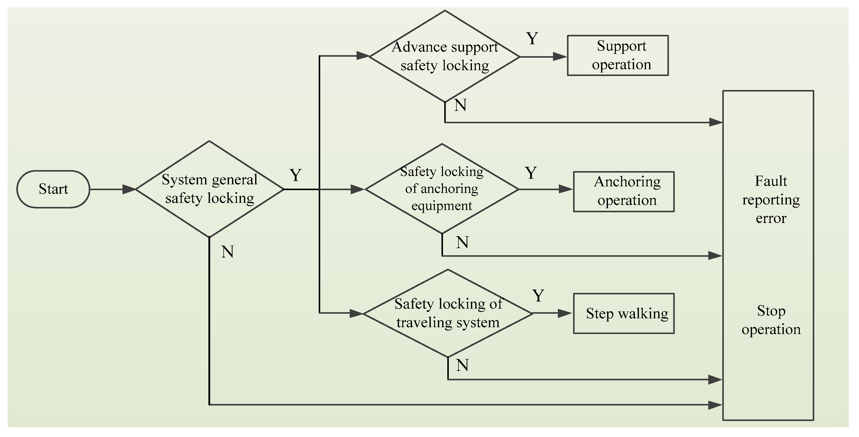
Because the combined support and anchor equipment studied herein has the functions of walking, supporting, bolting, etc., the sensor module should comprise monitoring sensors at the advanced support equipment position, the bolter position, and the walking equipment position. The monitoring sensors at the advanced support equipment position are installed at the four corners on the top beam of the support equipment to monitor the distance between the advanced support system and the other sub-equipment or obstacles during movement support. The monitoring sensors at the bolter position are installed on the support base of the jumbolter to monitor the distance between the jumbolter and the surrounding obstacles when the jumbolter is not being operated. The monitoring sensors at the walking equipment position are installed at the four corners of the gantry frame to monitor the distance between the whole machine and the obstacles in the moving and turning process. The logic diagram of the sensor module is shown in
Figure 1.
S1: Initialize the safety interlock system of support and anchor equipment.
S2: Judge whether the general safety interlock system of the stepping-type combined support and anchor equipment is locked. If yes, the next step is performed; if no, the system stops running and displays an error report.
S3: Judge whether the safety interlock system of the advanced support equipment is locked. If yes, the next step is performed; if no, the system stops running and displays an error report.
S4: Judge whether the safety interlock system of the bolter is locked. If yes, the next step is performed; if no, the system stops running and displays an error report.
S5: Judge whether the safety interlock system of the walking equipment is locked. If yes, the next step is performed; if no, the system stops running and displays an error report.
3. Design of a Logic Control Module for Safety Interlock System
Due to the complex working conditions of the combined support and anchor equipment, the flow demand of the hydraulic system varies greatly, so a single mode of flow control can barely meet the needs of actual operation. This is the reason why this paper adopts pump-valve collaborative control. At present, there are two types of pump-valve collaborative control: the parallel type and tandem type. The parallel type is composed of a relatively independent pump control system and valve control system; the tandem type is composed of control valves in series in the pump control circuit. The parallel type has high system reliability and working efficiency, but two independent hydraulic circuits are needed, so the system structure is complex. The tandem type only requires one oil source, so it has the advantages of simple structure, low cost and high reliability [
13]. Considering the mechanical structure and application position of the studied equipment, this paper chooses the tandem-type pump-valve collaborative control system as the control mode of the power system.
3.1. Modelling of the Pump Control Part for Pump-Valve Collaborative Control System
This paper chooses to power the system by using a permanent magnet synchronous motor (PMSM) to drive the plunger pump.
3.1.1. Mathematical Model of PMSM in a Natural System of Coordinates
The basic equation of PMSM in a natural system of coordinates is established as follows [
14,
15]:
where
where
Lm is the stator mutual inductance (H);
Lz is the stator leakage inductance (H);
ψA,
ψB, and
ψC are the flux linkage of the three-phase winding (Wb);
ψf is the flux linkage of the fundamental wave of the permanent magnet (Wb);
iA,
iB, and
iC are the current of the three-phase winding, A;
uA,
uB, and
uC are the phase voltage of the three-phase winding (V);
pn is the pair of poles;
R is the resistance of the three-phase winding (Ω);
θe is the rotor electrical angle (rad);
θm is the mechanical angle (rad);
ωe is the electrical angular velocity (rad/s);
ωm is the mechanical angular velocity (rad/s);
Te is the electromagnetic torque (N·m).
3.1.2. Mathematical Model of PMSM in a Synchronous Rotating Reference Frame
Under the constraint of constant amplitude, the Clarke transformation and the Park transformation were performed successively to convert the PMSM equation from the natural system of coordinates to the synchronous rotating reference frame
d-
q. The coordinate transformation matrix was
TCP:
where
ud and
uq are the
d-
q shaft voltage (V);
id and
iq are the
d-
q shaft current (A);
ψd and
ψq are the
d-
q shaft flux linkage (Wb);
Ld and
Lq are the
d-
q shaft inductance (H).
Equation (7) is rewritten into the symmetric matrix equation below:
The electromagnetic torque (
Te) is:
The output flow
Qp of the hydraulic pump can be expressed as:
where
n is the revolving speed of the hydraulic pump (r/min);
D is the rated displacement of hydraulic pump (L/r);
Kc is the leakage coefficient of the hydraulic pump;
Ps is the inlet pressure of the overflow valve (MPa).
The output oil of the pump control system passes the overflow valve to stabilize the system pressure. From the internal flow balance equation of the overflow valve and the balance equation of valve element stress, the transfer function between the inlet pressure of the overflow valve
Ps and the overflow quantity
Qr can be obtained [
3,
11]:
where
mR is the overflow valve element mass (kg);
AR is the equivalent area of overflow valve element (m
2);
A is the sectional area of overflow valve element (m
2);
ω is the valve port area gradient;
x0 is the spring offset at the balance point (m);
θ is the intersection angle between the flux axis line and valve element axis line;
KR is the overflow valve spring equivalent stiffness;
Qr0 is the steady-state value of overflow quantity;
Ps0 is the system pressure at the balance point (MPa);
Ks is the spring stiffness;
Qp is the hydraulic pump output flow;
QL is the load flow.
Therefore, the overflow valve inlet pressure can be expressed as:
where
Km is the motor speed gain coefficient;
τm is the time constant;
um is the control voltage signal;
KR is the equivalent stiffness of the overflow valve spring.
3.2. Modelling of Valve Control Part of Pump-Valve Collaborative Control System
In order to facilitate analysis of the valve control process of the pump-valve collaborative control system, this paper takes the activity of a hydraulic cylinder as the research object and establishes the relationship equation between input current and output flow [
13,
16]:
where
ωsv is the inherent frequency of the valve (rad/s);
is the damping ratio of the valve;
Ksf is the valve’s main spool displacement gain (m/A);
xv is the spool displacement.
Suppose the initial volume of the two cavities of the piston is
V10 =
V20 =
V0, and
A1y V0, A
2y V0; then, the flow continuity equation and the force balance equation of the hydraulic cylinder are:
where
Ctc is the total leakage coefficient.
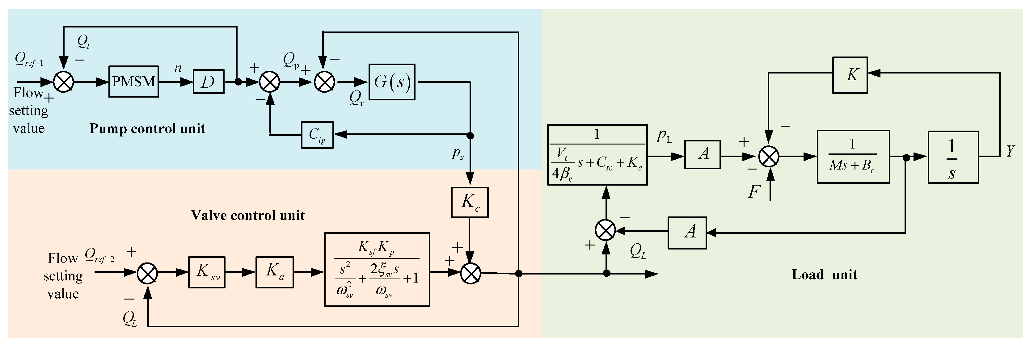
Figure 2 shows the control block diagram of the established pump-valve cooperative compound control system.
3.3. Valve Control System Based on Feedforward–Feedback Optimization
General hydraulic control systems have a time lag; that is, when a large deviation between the controlled object and the set value occurs, PID is driven to produce a reasonable adjustment. In a different way, following the compensation principle, a feedforward control system adjusts according to the change in perturbation or the given value. It has control according to the magnitude of the disturbance after the disturbance takes place and before the controlled variable changes to compensate for the impact of the disturbance on the controlled variable. Therefore, in order to improve the stability of the designed safety interlock control system herein, a feedforward control system was introduced to optimize the valve control system, as shown in
Figure 3. In
Figure 3, the feedforward is inputted to compensate for the steady-state error brought about by the flow change of the object, and the load current feedforward is inputted to compensate for the steady-state error brought about by load disturbance.
4. Design of the Executor Module
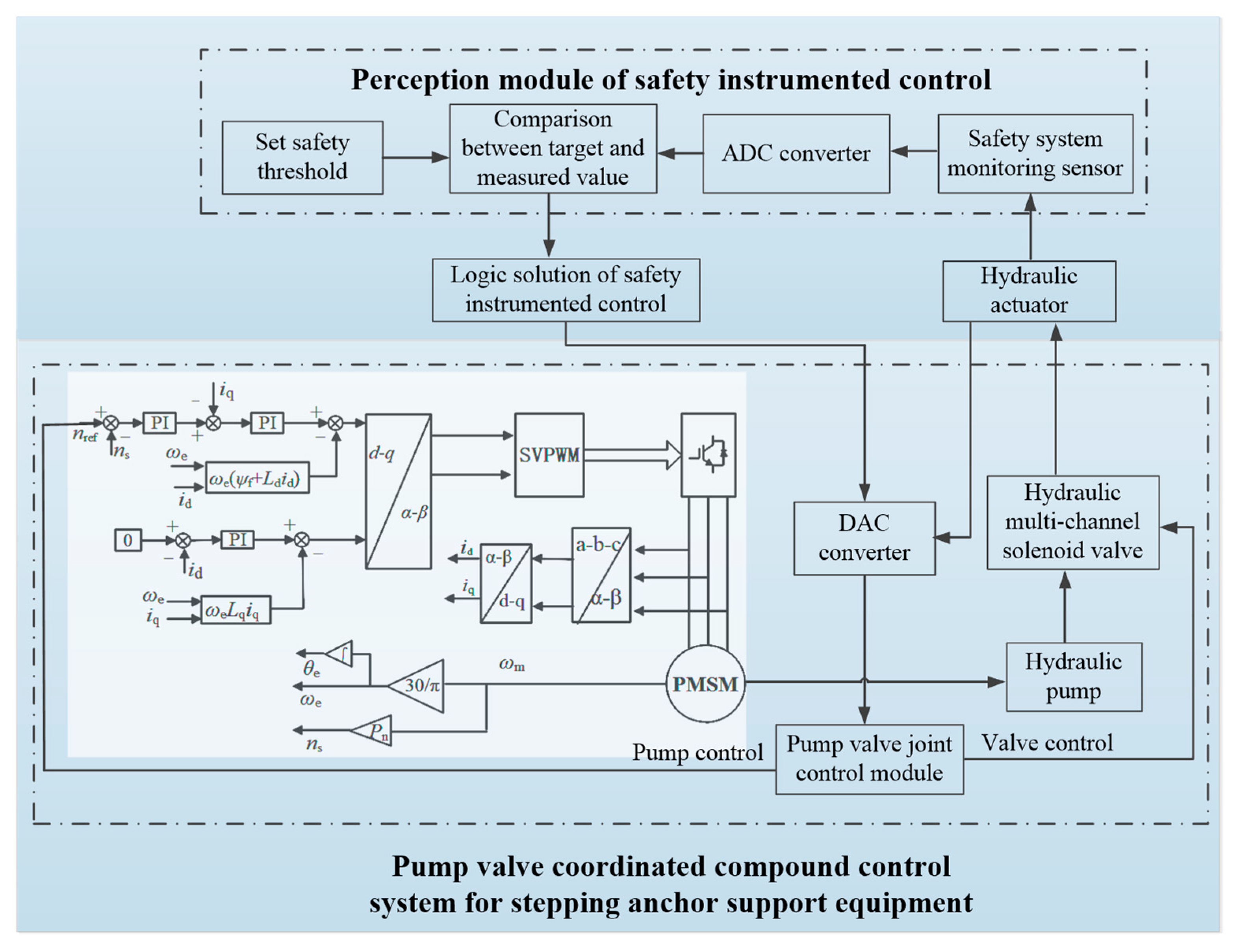
The logical solution module encompasses signal processing, analysis and judgment, decision output and other functions. First, the information collected by the sensor module is inputted into the logic control circuit through the A/D conversion module for comparative analysis with the preset threshold value. The logic module determines whether to perform walking or turning according to the input information into the logic control circuit, so as to avoid collision between the equipment and other equipment or personnel. At the same time, the safety interlock system of the equipment protects the pump-valve collaborative control system of the power unit to prevent the malfunction or maloperation of the equipment, so as to improve the stability and safety of the equipment. The working principle of the logic solution and executor module is shown in
Figure 4.
S1: The signal measured by the sensor module is converted into a digital signal through the A/D conversion module.
S2: The logic control circuit in the logic module is connected to the A/D conversion module to receive the measured data, and then performs amplification, filtering and logical judgment according to the allowable safe value set by the equipment.
S3: The decision signal is transmitted into the electromagnetic valve group and the PMSM driver in the executor module, so as to realize the real-time dynamic control of the pump-valve electrohydraulic system.
S4: The sensor module updates the monitored movement state of the combined stepping-type support and anchor equipment, and repeats the work in steps 1–3.
5. Experiment on the Safety Interlock System of Combined Stepping-Type Support and Anchor Equipment
In order to realize the synchronization of the drivage, bolting and supporting processes and improve efficiency, the hardware equipment is constructed according to the control method of the safety interlock system for the combined support and anchor equipment, as shown in
Figure 5. The experimental device of support and anchor equipment is shown in
Figure 6.
The safety interlock system of the combined stepping-type support and anchor equipment, shown in
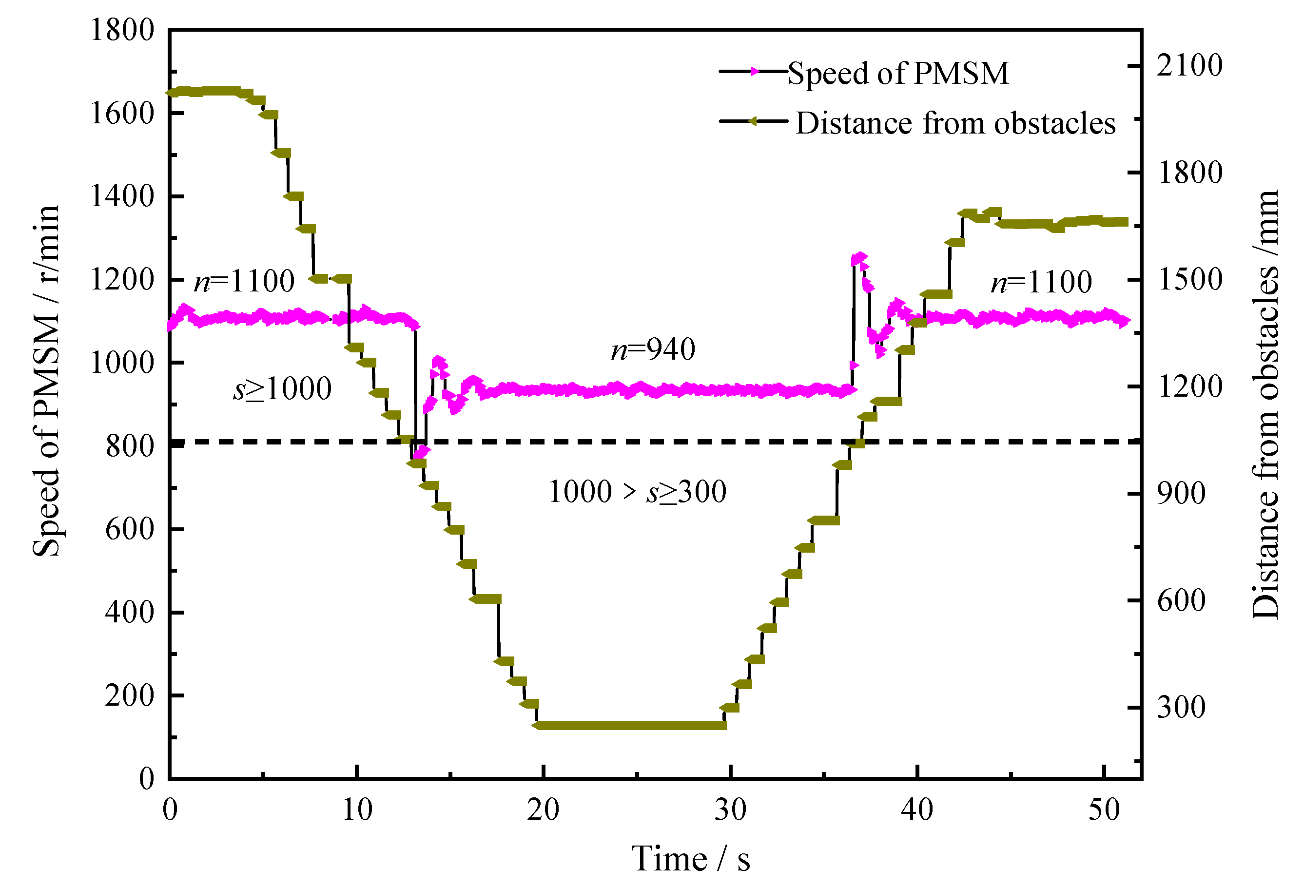
Figure 5, first arranges ultrasonic sensor groups at key positions around the equipment to build a virtual working space. When the equipment moves or operates, the safety interlock control system constantly updates the current threshold value, and transmits the control signal to the pump-valve compound control system. An experiment was carried out that targeted the safety interlock control system while the equipment was moving or turning. A three-level control mode was preset according to the distance between the equipment and the obstacle. The experimental results are shown in
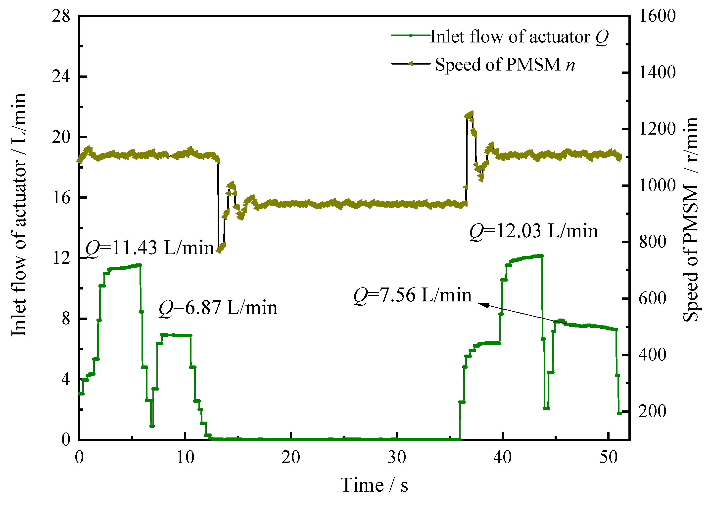
Figure 7.
According to
Figure 7, when the distance from the obstacle (s) is ≥1000 mm, the PMSM operates at a constant speed (ns = 1100 r/min); the moment the distance from the obstacle becomes less than 1000 mm, the revolving speed of the PMSM rapidly drops, fluctuates slightly, and then stabilizes at 940 r/min after 0.2 s; the moment the distance from the obstacle becomes more than 1000 mm, the revolving speed of the PMSM surges to 1100 r/min and remains stable.
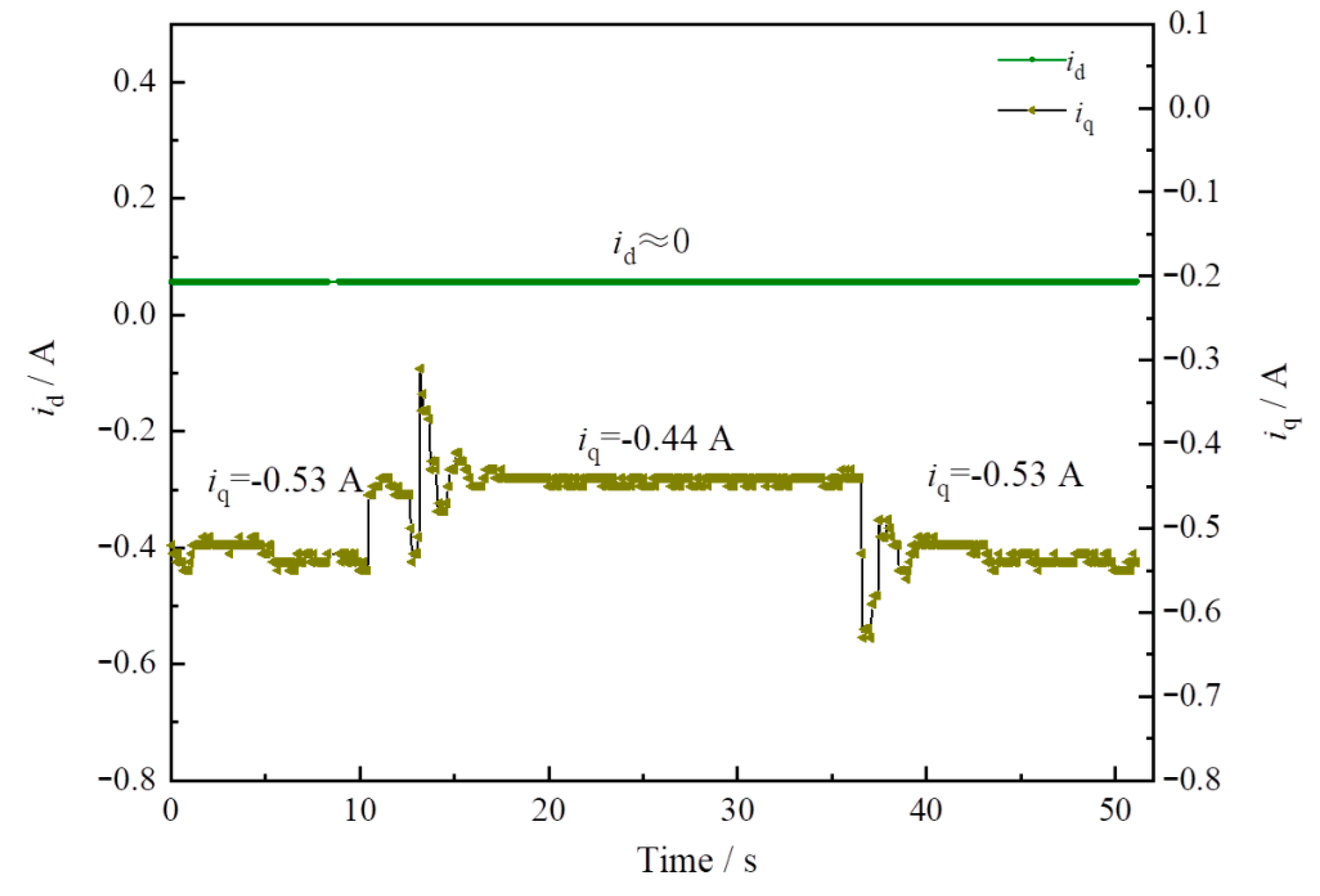
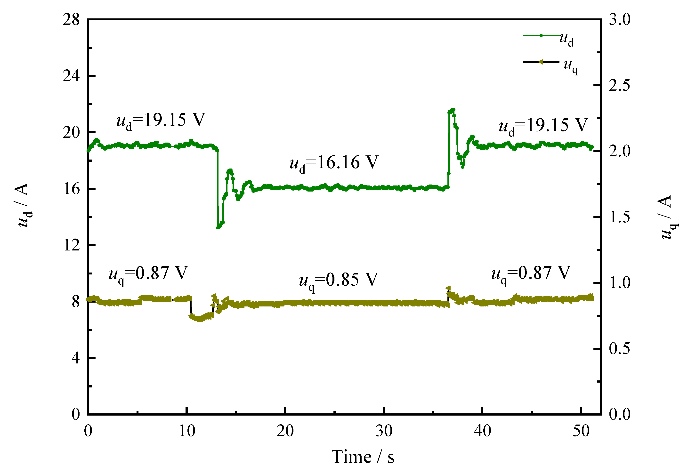
In the pump control system, the mechanical characteristics of the PMSM are controlled according to Equations (7) and (8). According to
Figure 8 and
Figure 9, the q-axis current values and the d-axis voltage values of the motor change with the distance between the equipment and the obstacle, and the change law is the same as the motor speed change law—that is, when the distance between the equipment and the obstacle is small, there is a risk of collision, so the control current and voltage of the motor are reduced to protect the equipment from damage.
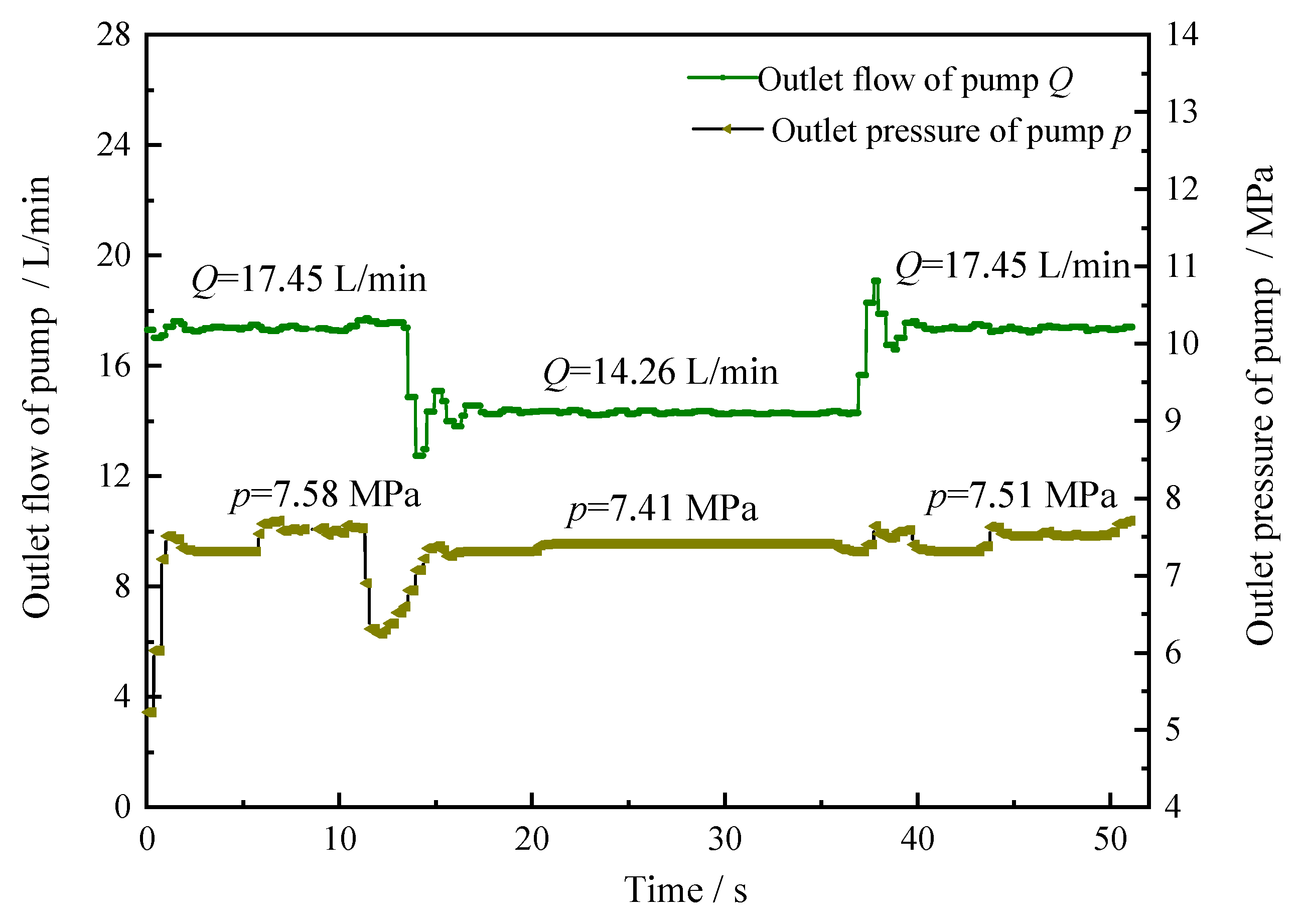
It can be further seen from the flow change curves of the total pump outlet flow and the actuator in
Figure 10 and
Figure 11 that the moment the equipment moves to less than 1000 mm from the obstacle, the pump outlet flow decreases from 17.45 L/min to 14.26 L/min within just 0.3 s. At the same time, the system pressure changes accordingly at different stages to prevent equipment malfunction damage to the surrounding obstacles.
6. Conclusions
The safety interlock system is an important part of combined support and anchor equipment, which plays a crucial role in ensuring the safety of the equipment in stepping-type movements, supporting and bolting operations. Based on the mobile safe operation requirements for the combined stepping-type support and anchor equipment, this paper presents a safety interlock protection logic diagram, completes the design of a sensor module and a pump-valve collaborative control system for the safety interlock system, establishes an experimental platform for the safety interlock control system of the combined stepping-type support and anchor equipment, and verifies the reliability of the safety interlock system and the closed-loop safety interlock control. This study is of great significance for improving the efficiency of collaborative operation on roadways and reducing the incidence of coal mine accidents.
Author Contributions
All of the authors contributed to the work. P.W. proposed the key ideas; G.S., P.W. and W.Y. analyzed the key contents using a simulation and wrote the manuscript; P.W. obtained the financial support for the project leading to this publication; G.S., P.W. and P.J. modified the manuscript. All authors have read and agreed to the published version of the manuscript.
Funding
This work was financially supported by the Open Fund of State Key Laboratory of Mining Response and Disaster Prevention and Control in Deep Coal Mines (grant no. SKLMRDPC20KF12); and Open Fund of Anhui Key Laboratory of Mine Intelligent Equipment and Technology (grant no. ZKSYS202103).
Institutional Review Board Statement
Not applicable.
Informed Consent Statement
Not applicable.
Data Availability Statement
Not applicable.
Acknowledgments
The authors are grateful to the editors and the anonymous reviewers for their insightful comments and suggestions.
Conflicts of Interest
The authors declare no conflict of interest.
References
- Wang, B. Current status and trend analysis of readway driving technology and equipment in coal mine. Coal Sci. Technol. 2020, 48, 1–11. [Google Scholar]
- Wang, H.; Wang, J.; Zhang, X. Theory and technology of efficient roadway advance with driving and bolting integration. J. China Coal Soc. 2020, 45, 2021–2030. [Google Scholar]
- Wang, G.; Ren, H.; Pang, Y.; Cao, X.; Zhao, G.; Chen, H.; Du, Y.; Mao, S.; Xu, Y.; Ren, S.; et al. Research and engineering progress of intelligent coal mine technical system in early stages. Coal Sci. Technol. 2020, 48, 1–27. [Google Scholar]
- Liu, F.; Cao, W.; Zhang, J.; Cao, G.M.; Guo, L.F. Current technological innovation and development direction of the 14th Five-Year Plan period in China coal industry. J. China Coal Soc. 2021, 46, 1–15. [Google Scholar]
- Wang, G.; Ren, H.; Zhao, G.; Zhao, G. Analysis and countermeasures of ten ‘pain points’ of intelligent coal mine. Ind. Mine Autom. 2021, 47, 1–11. [Google Scholar]
- Yang, J.; Ge, S.; Wang, F.; Luo, W.; Zhang, Y.; Hu, X.; Zhu, T.; Wu, M. Parallel tunneling: Intelligent control and key technologies for tunneling, supporting and anchoring based on ACP theory. J. China Coal Soc. 2021, 46, 2100–2111. [Google Scholar]
- Zhang, X.; Yang, W.; Xue, X.; Zhang, C.; Wang, J.; Mao, Q.; Lei, M.; Du, Y.; Ma, H.; Zhao, Y.; et al. Challenges and developing of the intelligent remote controlon roadheaders in coal mine. J. China Coal Soc. 2022, 47, 579–597. [Google Scholar]
- Javaid, F.; Wang, A.; Sana, M.U.; Husain, A.; Ashraf, I. Characteristic Study of Visible Light Communication and Influence of Coal Dust Particles in Underground Coal Mines. Electronics 2021, 10, 883. [Google Scholar] [CrossRef]
- Javaid, F.; Wang, A.; Sana, M.U.; ul Hassan, H.Z.; Ashraf, I. A dual channel and node mobility based cognitive ap-proach to optimize wireless networks in coal mines. J. King Saud Univ.—Comput. Inf. Sci. 2022, 34, 1486–1497. [Google Scholar]
- Javaid, F.; Wang, A.; Sana, M.U.; Husain, A.; Ashraf, I. An Optimized Approach to Channel Modeling and Impact of Deteriorating Factors on Wireless Communication in Underground Mines. Sensors 2021, 21, 5905. [Google Scholar] [CrossRef] [PubMed]
- Xie, L.; Lundteigen, M.A.; Liu, Y. Performance assessment of K-out-of-N safety instrumented systems subject to cascading failures. ISA Trans. 2021, 118, 35–43. [Google Scholar] [CrossRef] [PubMed]
- Meng, H.; Kloul, L.; Rauzy, A. Modeling patterns for reliability assessment of safety instrumented systems. Reliab. Eng. Syst. Saf. 2018, 180, 111–123. [Google Scholar] [CrossRef]
- Xie, W. Research on Serial Type Pump-Valve Coordinated Electric-Hydraulic Servo Control System. Master’s Thesis, Beijing University of Technology, Beijing, China, 2015. [Google Scholar]
- Rajendra, T.; Pragasen, P. Mathematical Model of an Interior PMSM With Aligned Magnet and Reluctance Torques. IEEE Trans. Transp. Electrif. 2020, 16, 647–658. [Google Scholar]
- Yuan, L.; Hu, B.X.; Wei, K.Y.; Chen, S. Control Principle and MATLAB Simulation of Modern Permanent Magnet Synchronous Motor; Beijing University of Aeronautics and Astronautics Press: Beijing, China, 2016; pp. 4–11, 82. [Google Scholar]
- Wang, M. Research on the Control Method of the Serial Type Pump-Value Coordinated Electro-Hydraulic Servo System. Master’s Thesis, Harbin Institute of Technology, Harbin, China, 2016. [Google Scholar]
| Publisher’s Note: MDPI stays neutral with regard to jurisdictional claims in published maps and institutional affiliations. |
© 2022 by the authors. Licensee MDPI, Basel, Switzerland. This article is an open access article distributed under the terms and conditions of the Creative Commons Attribution (CC BY) license (https://creativecommons.org/licenses/by/4.0/).


