1. Introduction
In wireless transmissions, the security and privacy of their broadcast nature become a critical issue as it operates not only in the civil area but also in the military. For example, privacy information in health care, the journey or location of vehicles in transportation and the position or confidential information of the targets need to be protected. Regarding security protection for wireless communications, several conventional approaches, such as cryptography [
1] or physical layer security [
2,
3,
4], have been implemented. These methods only target preventing the confidential content of messages from being stolen by eavesdroppers. Nevertheless, some scenarios are dedicated to avoiding being attacked, such as jamming when the existence (privacy) of transmissions is revealed. For example, in the case of a self-driving car, the controlling signals need to be completely secured or hidden from the adversary. Moreover, the location or itinerary of vehicles needs to be kept private. Their revelations to the attacker may cause security issues or accidents. Therefore, covert communication has emerged as a potential solution for dealing with the issue of privacy.
Covert or low-probability-of-detection communication refers to scenarios where the transmitter sends its message to the receiver such that the warden cannot detect (or can detect at a low probability) the existence of transmissions [
5]. The square root law (SRL) for covert communication was firstly introduced in additive white Gaussian noise (AWGN) channels for covert or low-probability-of-detection communication with two important measures: the warden’s detection error probability
, defined as the sum of the probabilities of a false alarm when the transmitter is not sending and missed the detection when the transmitter is sending, and the covert throughput, defined by the number of bits transmitted reliably over
N channels subject to the constraint of
for covert requirement
[
5]. Then, SRL can be used to preside the covert communication, in which, the
bits can be transmitted over
N channels covertly and reliably. After proving the SRL in additive white Gaussian noise (AWGN) channels [
5], it was developed to discrete memoryless channels (DMCs) [
6,
7,
8], in which, the Big-O notation characterizes the constant hidden. Then, [
9] extended the study to covert communication in DMCs under some constraints related to the covertness. In [
10], the authors showed that the Gaussian signalling can be optimal under only a covertness constraint. Thus, the Kullback–Leibler divergence asymmetry property can optimize the Gaussian signalling with other constraints to [
10]. However, SRL has a weakness, as a positive covert rate cannot be guaranteed when the number of channels tends to infinity. This means that the covert rate
tends to 0 when
N tends to infinity. This problem of SRL was later addressed and solved by [
11,
12,
13]. In [
11], the study pointed out that a signal-to-noise ratio (SNR) threshold will impact the detection of the transmitted signal if the received signal power is less than this threshold. Thus, it can be seen as a noise uncertainty when the noise power estimation does not match the actual noise power. Hence, the noise uncertainty is useful in covert communication since it could be a medium to hide a message. The study in [
12] proved that there will be a positive covert rate even for an infinite number of channels if the legitimate has noise uncertainty. Thus, the covert throughput was analyzed in [
13] based on two noise uncertainty practical models under AWGN channels.
In general, two well-known approaches adopted for covert communications have been widely investigated in the literature. The key idea of the first approach is to take advantage of various sources of the adversary’s uncertainty to guarantee the covertness, e.g., adversary’s noise uncertainty in [
12,
13], uncertainties of transmission time [
14], channel state information [
15] and transmit power [
16]. Later, the noise uncertainty was extended to uninformed jamming [
17] and artificial noise (AN) from a friendly jammer [
18] or from a full-duplex receiver [
19,
20,
21]. Using AN at the FD receiver, the receiver receives the covert message while jamming the warden to make it harder to detect the covert message [
19,
20,
21]. However, two critical questions arise: (1) in the case of the covert receiver being a low cost-device, i.e., IoT users with hardware that is not complex and does not have enough energy to simultaneously carry out two such roles, and (2) jamming by the covert receiver, which receives the covert message, may help the adversary to detect the presence of covert transmission. Hence, jamming while receiving the covert information by the covert receiver may not be practical in a real scenario. For the second approach, other works considered superimposing the covert message into another message of existing transmissions, termed as hiding messages into overt transmissions, and exploited transmit power control [
22] and random transmit power [
23]. The basic idea of the second approach is to guarantee covertness by enlarging the dynamic range of the adversary’s uncertainties via the existing transmission. Most recently, [
24] showed, for the first time, that the warden cannot detect the covert message if the overt message where the covert message is superimposed onto is not decoded. This finding can be referred to as
decoding uncertainty at the warden.
Inspired by [
24] and the full-duplex receiver scheme in [
19,
20,
21], we introduce a novel scheme of hiding messages into existing overt transmissions with a FD overt receiver. Different from [
19,
20,
21], the artificial noise jamming signal is transmitted by the overt receiver with just naive intention to secure its connection with the transmitter [
25] and, thus, the presence of the covert transmission will not be detected via artificial noise jamming. More specifically, the superposition signal of the covert and overt messages is transmitted at a fixed transmit power while the overt receiver emits the AN to secure its connection. With this setting, we find that, in order to detect the covert message, it is necessary for the warden to decode the overt message and, even if the overt message is decoded, the covertness still can be guaranteed due to the adversary’s uncertainty in receiving AN powers. Then, an efficient AN and the improved performance of the secure connection of the overt transmission leads to an improvement in the covertness. In this paper, performances were evaluated by using three metrics: the adversary’s average detection error probability
, the covert throughput
and the overt throughput loss
. The main contributions of the paper are listed as follows:
We propose a scheme to hide the covert information by exploiting the existing secure connection transmission with the aid of artificial noise generated by a full-duplex overt receiver, which has not been considered in literature.
The artificial noise used for improving the secure connection transmission can also be exploited for improving covert transmissions.
The artificial noise can be further improved if the channel state information between the over receiver and the warden is unknown at the warden, which is also known as the uncertainty of artificial noise power.
This paper is organized as follows.
Section 2 will describe the system model with one transmitter and two receivers, as well as a warden.
Section 3 presents the optimum detection of the warden. The covert throughput and the overt throughput loss are examined in
Section 4 and
Section 5, respectively. The numerical results will be shown in
Section 6.
2. System Model
We considered one transmitter (Alice) and two receivers—one (Carol) to receive overt messages,
v =
, and one (Bob) to receive covert messages,
u =
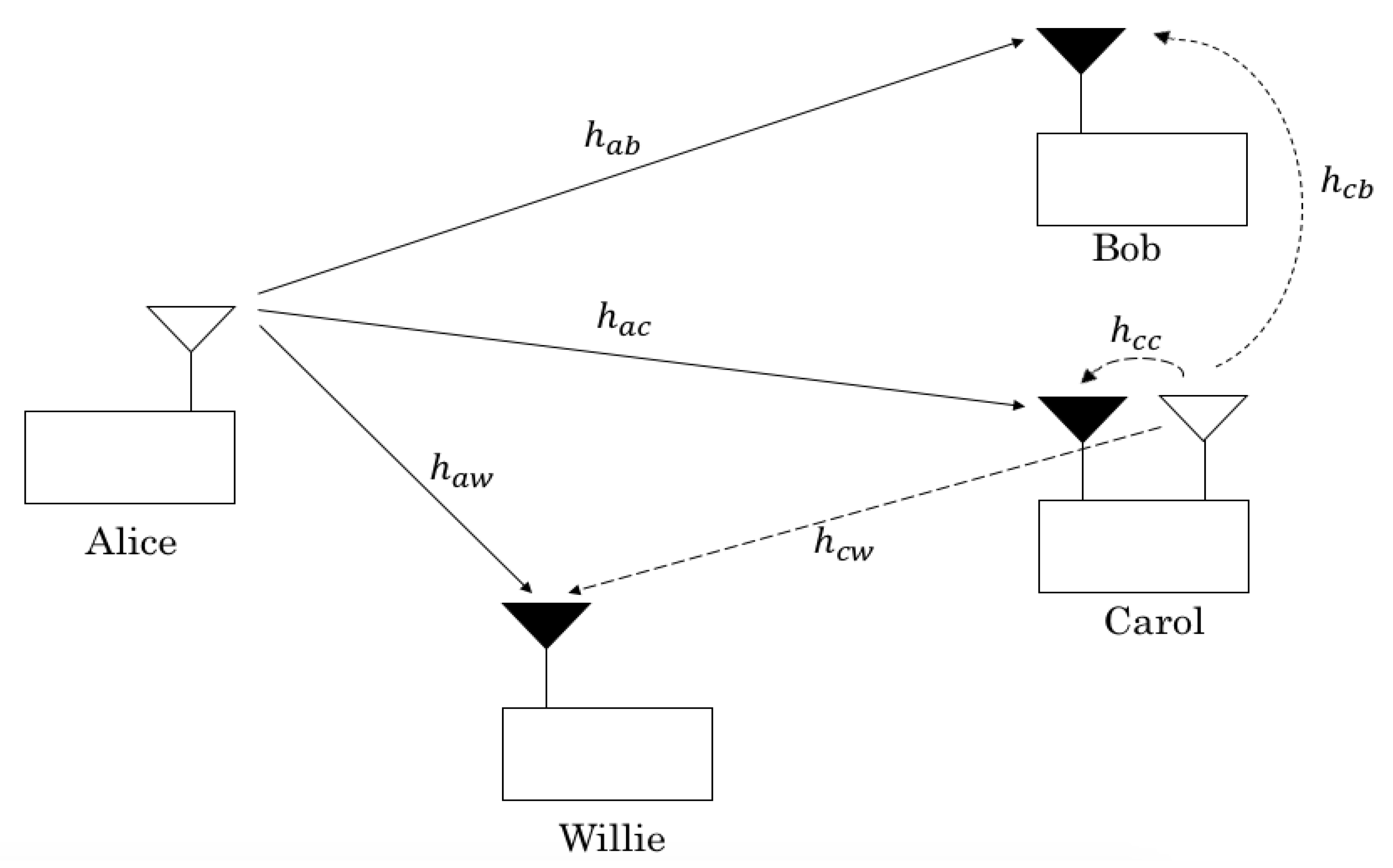
—and a warden (Willie) to detect the presence of covert transmission. The proposed system is illustrated in
Figure 1, where Carol equipped with two antennas operates at full-duplex mode to secure its connection to the warden [
19], whereas other nodes employ a half-duplex mode with a single antenna. The proposed scheme is under practical consideration of uplink transmissions, in which, the transmitter (an IoT device) opportunistically sends its covert message on top of the overt message as a camouflage while the overt receiver (a base station with an advanced receiver architecture) secures its connection. Here, the artificial noise is naively exploited to secure the connection for the overt user and, then, is opportunistically used to provide covertness for the covert user.
Considering the random coding used to generate codewords [
26], the codewords
and
are independently generated by random selection symbols from a complex normal distribution. To guarantee the covertness, the codebook of
is a share secret between Alice and Bob, whereas that of
is assumed as known to all users, including Willie. The transmitted signal from Alice, from Willie’s perspective, is given by
where
and
denote the null hypothesis that
has not been sent by Alice and the alternative hypothesis, respectively,
is the ratio of power allocated to the overt message and
is Alice’s total transmit power, which is always constant regardless of the covert transmission.
The quasi-static Rayleigh block fading channels is considered, where the channel gain is constant inside an
n symbols block and changes from one block to another independently [
22,
24]. Let the channel gain be
between nodes
i and
j, where
and
, in which nodes
and
w represent Alice, Bob, Carol and Willie, respectively, and have a Gaussian distribution with mean 0 and variance
. A high value of
means that the two users are close. Assuming that Alice sends pilot symbols for channel estimations before data transmissions, and assuming perfect channel estimation at all receiver nodes, node
j perfectly knows
. We further denote
,
as the background noise vector at node
j and assume that
has a complex Gaussian distribution with mean 0 and variance
, i.e.,
. It should be noted that Carol does not send their channel estimate to Alice. In addition, Bob will not send their channel estimate to Alice in order to avoid being detected by Willie. Hence, Alice does not know the channel information from them to other nodes and designs fixed transmission rates to Bob and Carol. This design is suitable for IoT applications with a requirement of strict latency as it does not require channel information feedback. For convenience, the parameter and metric notations are provided in
Table 1.
3. Warden’s Optimum Detection
After receiving the transmitted signal from Alice and artificial noise from Carol, the signal to be received at Willie is expressed as
where
is the AN signal transmitted by Carol and
is the transmit AN power. It will be proven that the distribution of
is identical under
and
if
is not decoded, and different if
is decoded. This means that Willie cannot detect the covert message
if the overt message
cannot be decoded. Moreover, since Willie has uncertainty in the received AN power,
, the covertness can still be guaranteed if
is decoded. In this section, the average total detection error probability, estimated over the event of Willie’s success and failure to decode
, is calculated. In detail, we considered two cases: Willie fails to decode
and Willie succeeds in decoding
, as follows.
3.1. Willie Fails to Decode
When Willie fails to decode
, they will perform the marginalized likelihood ratio test (LRT), i.e., averaging unknown
in the likelihood functions, as its optimum detection [
27], is
where (
denotes the expectation of the function
with respect to the random variable
X), under
, by treating
in (
2) as noise since Willie does not know the codebook of
, we have
and, under
, we similarly have
Then, we obtain from (
4) and (
5) that
The proof of (
6) is provided in
Appendix A. Hence,
.
Let
denote the mutual information between
and
, and
denote the transmission rate of the overt message. The design value of
will be determined in
Section 5. It follows from [
28] (Equation (
1)) that the event of
is a subset of the event that Willie fails to decode
. Then, the lower bound of the false alarm and missed detection probabilities, in the case that Willie fails to decode
, are given by
respectively, where
To achieve a high detection performance, the strategy of the warden Willie is to minimize the sum of the false alarm and missed detection probabilities (
) by choosing
properly. Since
under
is larger than that under
, Willie may choose
to obtain the minimum
which, since
is distributed exponentially with a scale of
, yields
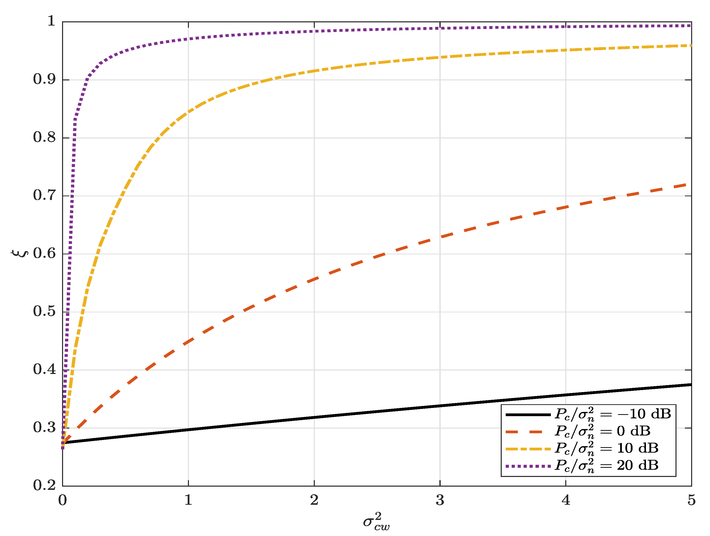
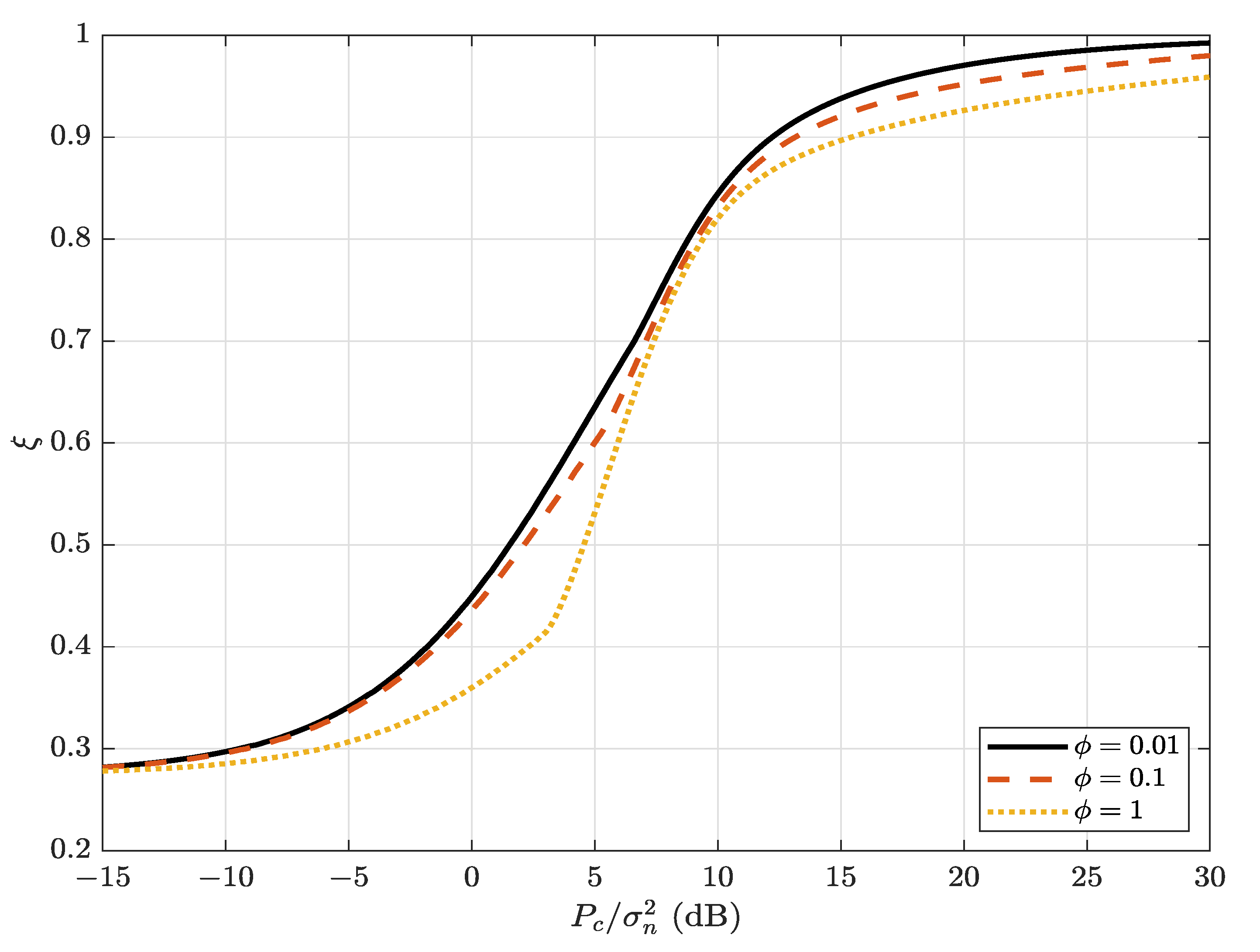
Remark 1. One can see from (9) that also represents the secure connection probability and increases as the AN transmit power increases. This means that the AN helps to not only secure the connection for the overt user but also to hide the message for the covert user. 3.2. Willie Succeeds in Decoding
When Willie succeeds in decoding
, they will perform the LRT of
where (
11) is derived from (
4) and (
5). As
(the best scenario for Willie’s detection),
converges to
Remark 2. One can see that, if Willie perfectly knows the channel gain via channel information feedback at Carol or perfectly knows their received AN power of , Willie can choose the detection threshold such that, from (12), the false alarm probability and missed detection probability are zero, i.e., , i.e., Willie can always detect the presence of the covert transmission if the overt message is decoded and removed. However, this channel information feedback is not considered in our system model and, hence, Willie has uncertainty in the received AN power, which still guarantees a certain covertness even if the overt message is decoded and removed. Since
has an exponential distribution with a mean of
, the false alarm and missed detection probabilities for decoding
at Willie, by assuming that Willie succeeds in decoding
, based on (
8) and (
12), are given by
where
, and
Willie attempts to minimize
by properly choosing
equal to
where its proof is provided in
Appendix B, and then
3.3. Average Total Detection Error Probability
In summary, the average total detection error probability, estimated over the event of Willie’s success and failure to decode
regardless of the number of symbols
n, can be determined as
which can be computed from (
10) and (
18). Here, we emphasize that the total detection error probability in (19) is the lower bound obtained from (10) and (18) and that it is necessary to consider (19) as the covertness measure, which is independent of the number of symbols under practical considerations.
Covert requirement: A covert communication can be achieved if for any covertness requirement . This means that the detection is ineffective, i.e., , at a sufficiently small .
4. Covert Throughput at the Covert User Bob
In this section, the covert throughput will be determined. The covert throughput of
between Alice and Bob is the average rate correctly received over many transmission bursts, i.e.,
, because the message is only correctly received on
transmissions [
15], with
being the decoding outage probability. Since Alice does not know
, they will transmit
at a fixed rate
. The received signal at Bob is given by
Assuming successive interference cancellation receiver type at Bob [
29], the covert message maximum rate is given by
if Bob cannot decode
, i.e.,
or, equivalently,
and, otherwise,
Since
has an exponential distribution with a mean of
with its cumulative distribution function (CDF) of
and
has an exponential distribution with a mean of
with its probability density function (PDF) of
The decoding outage probability, denoted as
, of the covert message
can be derived in a closed-form expression as
As in [
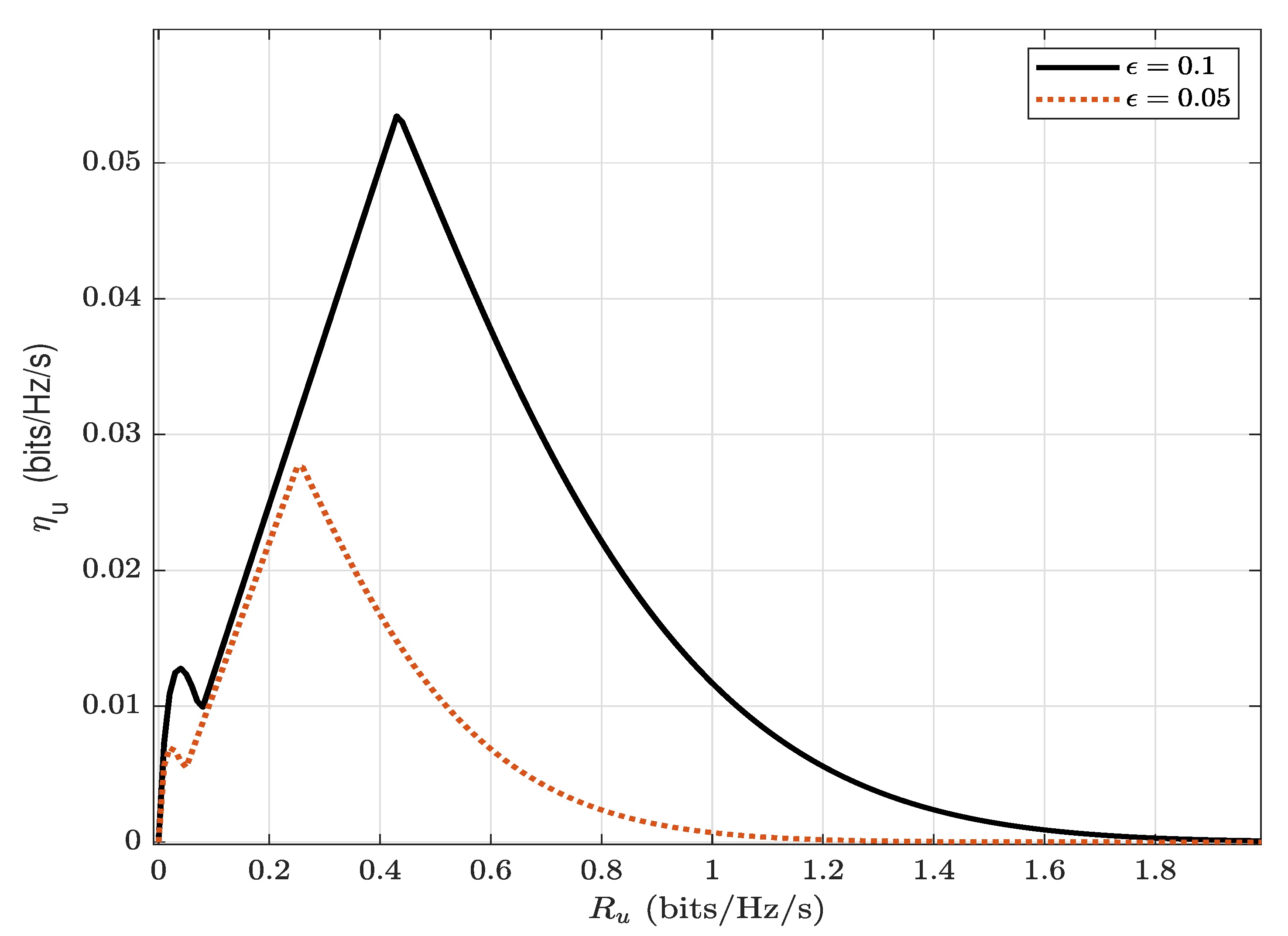
24], the covert throughput (bits/Hz/s) is expressed as
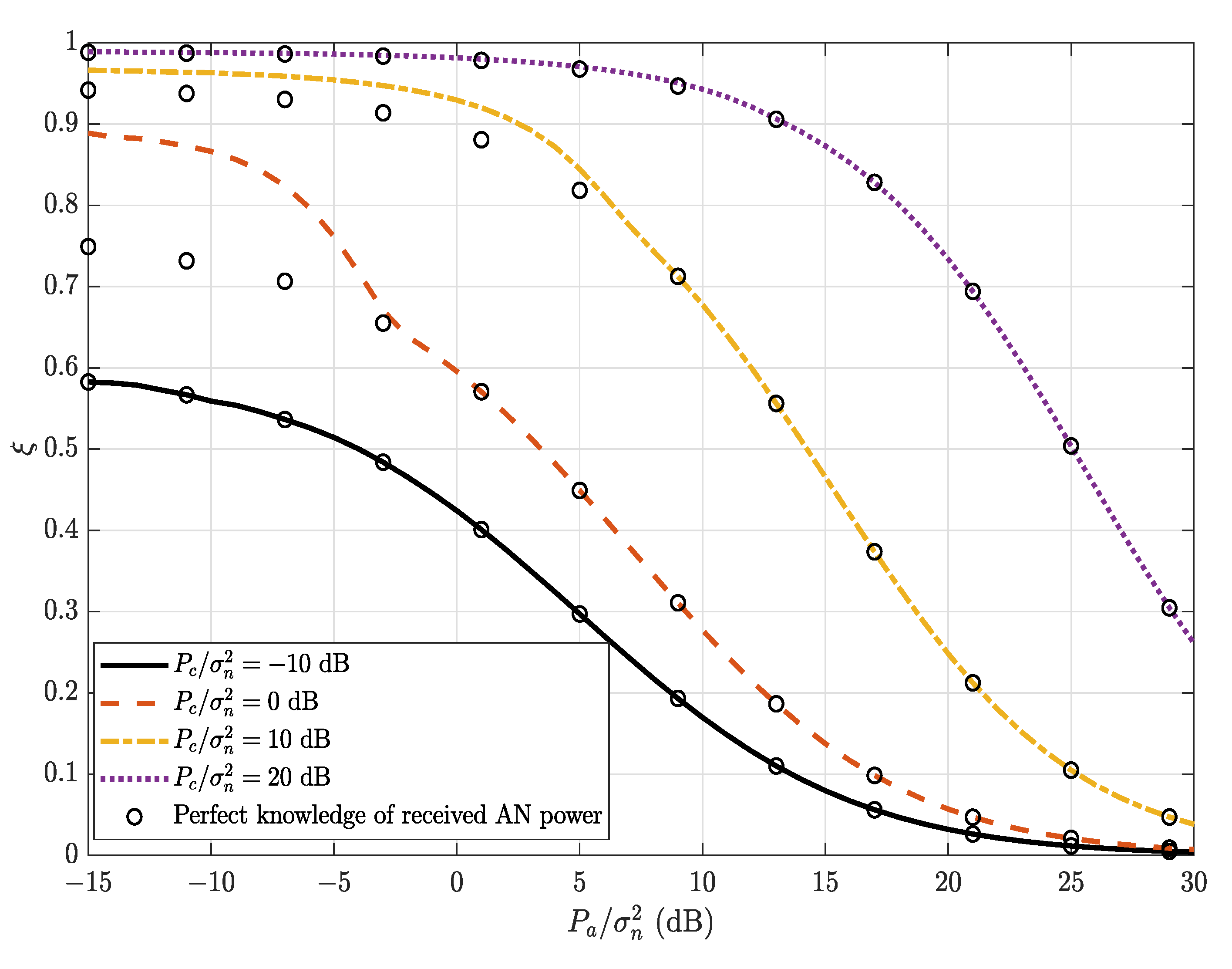
. In this paper, the covert throughput maximization problem is formulated as
where
represents the covertness requirement. Since
is a decreasing function of
(see
Figure 2),
is an increasing function of
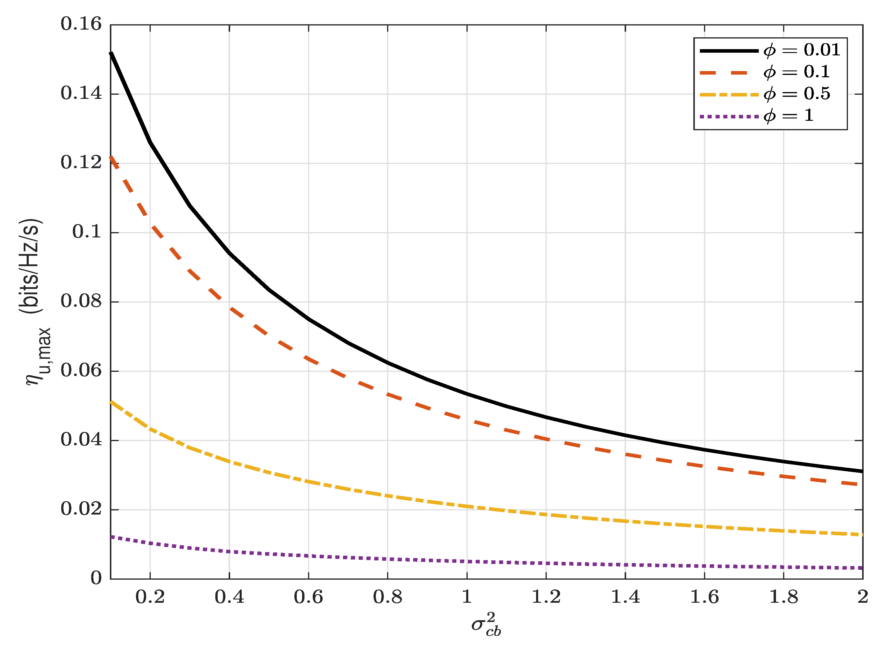
. Also, since
is a decreasing function of
(see
Figure 3), the constraint of
requires
less than a threshold
, where
is the solution of
. Hence,
is maximized when
. Therefore, the covert throughput (bits/Hz/s) is given by
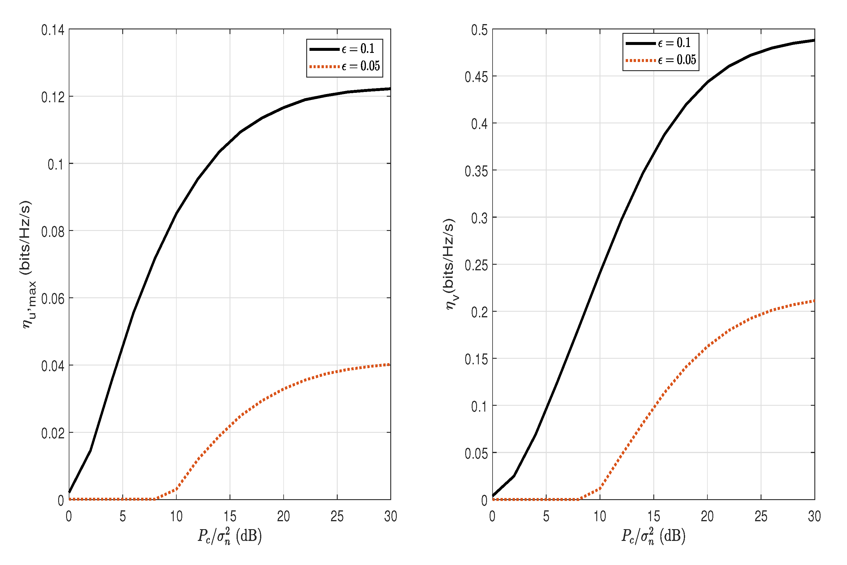
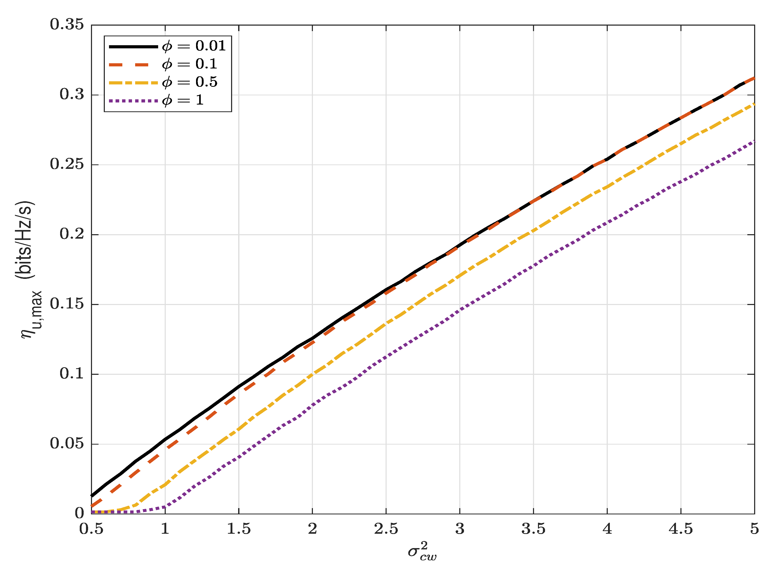
and its resulting maximum covert throughput is given by
To enable a positive covert throughput, the overt user needs to sacrifice its throughput for the covert message. Consequently, the next section presents the overt throughput loss.
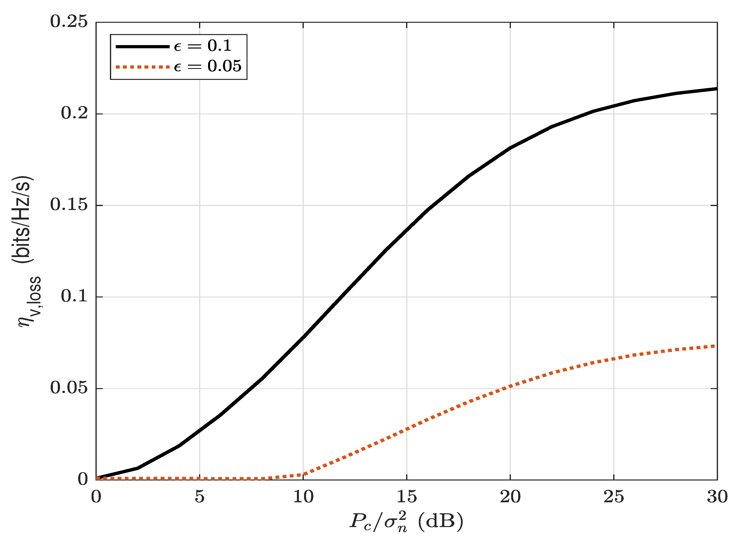
5. Overt Throughput Loss at the Overt User Carol
In this section, the loss of the overt throughput traded for the covert throughput is characterized. Under
, the received signal at Carol is given by
where
denotes the cancellation coefficient. Although the AN is known to Carol, it cannot be absolutely cancelled and, in practice, can be eliminated with a cancellation coefficient,
, where
[
30]. A low value of cancellation coefficient
indicates that the self-interference has nearly been cancelled (
: total cancellation;
: no cancellation). Since Carol does not know the presence of
, the capacity of
considering
as noise is given by
Alice considers transmitting the overt message at a fixed rate
due to unknown
. Since
has an exponential distribution with a mean of
with its cumulative distribution function (CDF) of
and
has an exponential distribution with a mean of
with its probability density function (PDF) of
the probability of overt decoding the outage probability is obtained by
The throughput (bits/Hz/s) of the overt message is given by
To maximize the throughput of the overt message, the overt transmission rate
should be chosen properly by numerical search. When
(no transmission of covert message), the overt throughput, denoted as
, can be obtained from (
34) and (
35),
Therefore, we obtain from (
35) and (
36) that the overt throughput loss (bits/Hz/s) is given by
which can be found by numerical search.


