Communication

Innovative Image Processing Method to Improve Autofocusing Accuracy

1
Department of Mechanical Engineering, National Cheng Kung University, Tainan 70101, Taiwan
2
Academy of Innovative Semiconductor and Sustainable Manufacturing, National Cheng Kung University, Tainan 70101, Taiwan
*
Author to whom correspondence should be addressed.
Sensors 2022, 22(13), 5058; https://doi.org/10.3390/s22135058
Submission received: 16 June 2022 / Revised: 29 June 2022 / Accepted: 4 July 2022 / Published: 5 July 2022
(This article belongs to the Special Issue Sensor-Based Precision Dimensional Measurement)

Abstract

:
For automated optical inspection, autofocusing microscopes play an important role in capturing clear images of the measured object. At present, the image processing part of optics-based autofocusing microscopes often has various factors, which makes it impossible to describe the image information of the semicircular (or elliptical) spot with a simple circle-finding method. Accordingly, this study has developed a novel algorithm that can quickly calculate the ideal center of the elliptical spot and effectively compensate the linearity of the focusing characteristic curve. A prototype model was used to characterize and verify the proposed algorithm. The experimental results show that by using the proposed algorithm, the autofocusing accuracy can be effectively improved to less than 1.5 μm.

1. Introduction

Automated optical inspection (AOI) has played a large role in manufacturing factories since it is able to provide accurate measurements and fast results for the inspection of defects [1,2,3]. Taking microscopic images of products and focusing is a fundamental function required for measuring and analyzing small defects [4]. During the capture of the microscopic images, focus drifts are often caused by environmental noises and result in blurred microscopic image [5]. Currently, manual focusing is a solution, but it is impractical, especially for large products due to its inaccuracy and being time-consuming. Hence, the autofocusing function is a solution with potential. In several steps prior to AOI processing, the image must be in focus, including image processing, image locating, and pattern matching [6,7]. Another application of the autofocusing function is high precision laser printing and laser machining [8]. Through the function, the laser energy can be focused on the machining areas. Therefore, many kinds of autofocusing devices and methods have been designed and proposed in the literature to realize automated capture for microscopic images and microscale fabrication using AOI, precise laser printing, and laser machining [9,10,11,12,13,14,15,16].
As introduced in [16,17], existing autofocusing technologies can be broadly classified as two kinds: passive control and active control. The autofocusing technologies with passive control are based on optimization of the image sharpness at different axial positions and find the real focal point via developed search algorithm. They are also called image-based autofocusing technologies, and they are robust and reliable. However, their main disadvantages are that they are time-consuming due to their heavy data processing [17,18,19] and that they might cause a false local maxima/minima [20].
The autofocusing technologies with active control are based on the assistance of an extra optical sensor, so they are called optics-based autofocusing technologies. Their main advantages are being highly accurate and time-saving in comparison with passive control autofocusing technologies [17,21]. As a result, autofocusing technologies with active control are popularly used in many AOI applications, precise laser printing, and laser machining with real-time and precise measurements [22,23,24,25,26,27,28,29,30,31,32]. As for the demand of critical requirements, the autofocusing technologies with active control are required to further improve their autofocusing accuracy. Accordingly, the purpose of the present study is to effectively improve the autofocusing accuracy of the autofocusing technologies with active control by using a novel algorithm.
To the best of our knowledge, WDI Wise Device Inc. has dominated the market of commercial autofocusing technologies with active control in recent ten years. References [16,33] described the detailed design of this autofocusing technology and a laser diode used as a light source. Using the centroids of the laser spots as feedback, the autofocusing function can be performed. However, the geometric laser beam variations or fluctuations with time degrade its autofocusing accuracy [34]. Therefore, in order to overcome this issue and improve the autofocusing accuracy, in general, two methods can be used. One method is to design and manufacture stable laser light sources [35,36,37], and the other is to suppress the effects of laser fluctuations computationally [2,38,39]. The latter is the focus and aim of this study.
Hereafter, some literature has been reviewed for diminishing the effects of laser fluctuations. In our published paper, a modified autofocusing algorithm was developed, and the distance L between the centroid and geometric center of laser spot image is used as the modified feedback signal [34], as shown in Figure 1, but this algorithm does not consider real geometric distortion of the laser beam. In our other previous studies [2,38,39], the autofocusing accuracy has further improved by using a motor and a rotating diffuser element, but this method increases the hardware cost. So, the accuracy of the focusing characteristic curve of the microscope is further enhanced by utilizing a proposed novel algorithm to effectively suppress the effects of geometric distortions in the current study. The feasibility of the proposed novel algorithm and prototype model have been demonstrated by using a series of experiments.

2. Adopted Autofocusing Structure and Experimental Setup

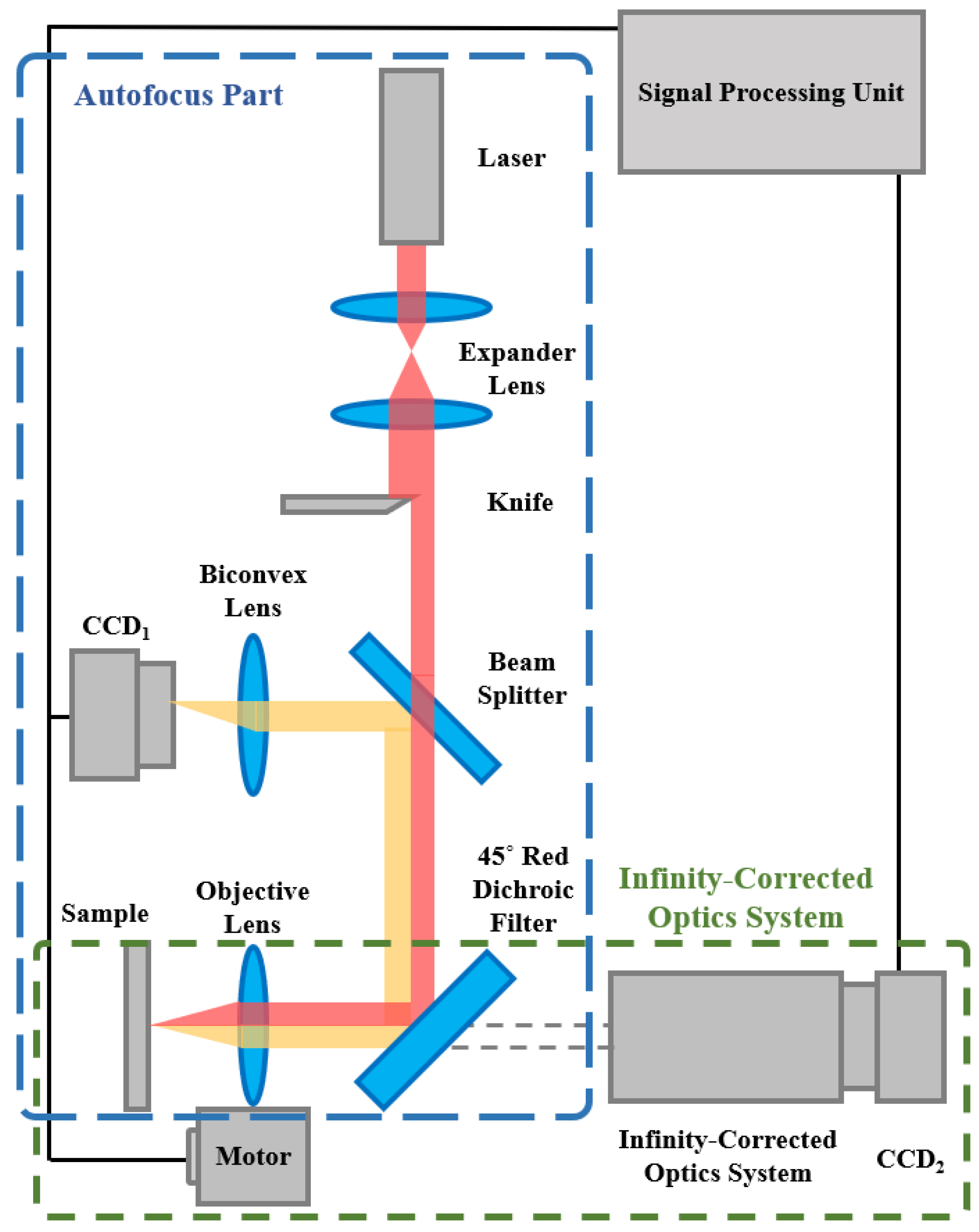
2.1. Adopted Autofocusing Structure

Figure 2 illustrates the basic autofocusing structure adopted in this study. In our previous studies, we identified the detailed design parameters of the autofocusing microscope [2,34]. To verify the performance of the proposed novel algorithm, a duplicate of the autofocusing microscope was used. As shown, the adopted autofocusing structure can be divided into the autofocus part and the infinity-corrected optics system part. The autofocusing function is operated in the autofocus part. A real-time microscopic image of the sample is obtained using the infinity-corrected and coaxial optics system.
According to our previous study [34], the distance L between the centroid and geometric center of the captured laser spot image on CCD1 changes linearly with the defocus distance δ (or axis move), as shown in Figure 3. A self-development algorithm is used to calculate and measure the variation of distance L (see Section 3). To achieve autofocusing function, the measured distance L was used as a position feedback signal to move the objective lens in real time by a precise motor (PI UPL120, unidirectional repeatability to 0.05 µm). Table 1 lists the selected values of each design parameter for the proposed prototype.

2.2. Experimental Setup of Prototype Autofocusing Microscope

The performance of the proposed algorithm was demonstrated by fabricating a prototype model of autofocusing microscope. The proposed algorithm was integrated into a self-development human machine interface (HMI) in commercial software of LabVIEW. The LabVIEW implementation includes the following functions: for the image processing, converting to a more ideal value of output format to enhance contrast and brightness in analysis data of image processing, and using the gray morphology function to adjust the speckle shape captured by CCD1. The function “clamp” measures the side edge of the speckle including top and bottom. Finally, the program in LabVIEW also captures the centroid and gravity center of the laser spot image and executes the defocus distance calculation analysis. Figure 4 shows the photograph of the prototype model of the autofocusing microscope. Figure 5 shows the proposed HMI. As shown in Figure 5, the left, middle, and right images present the original laser spot image captured by the CCD1, processed laser spot image, and real-time image of the sample, respectively.

3. Proposed Algorithm

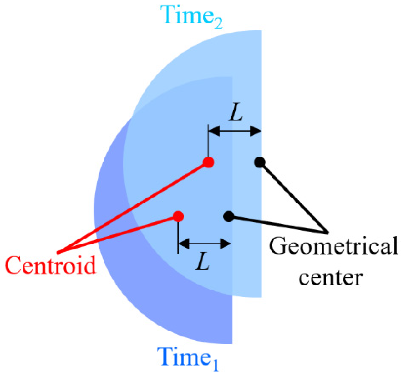
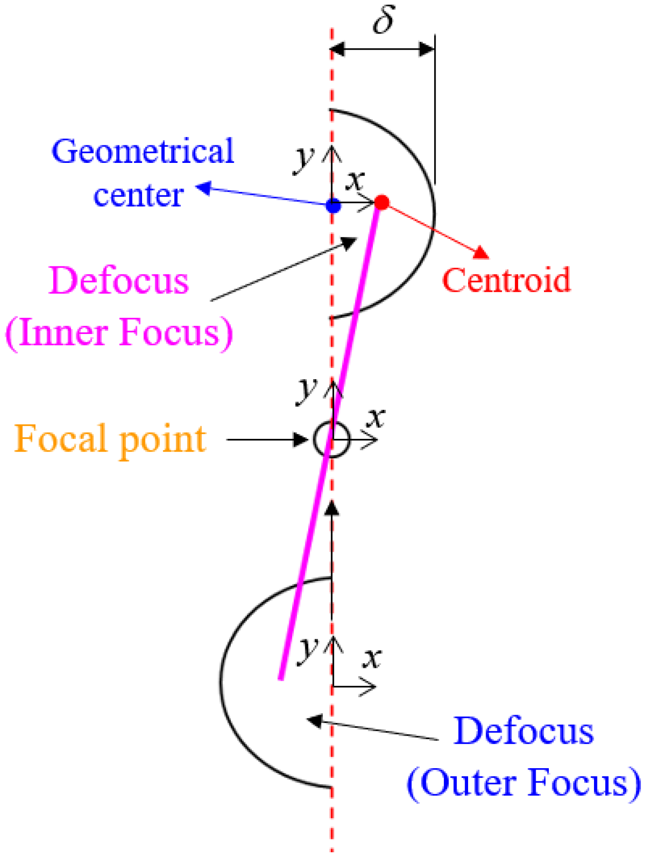
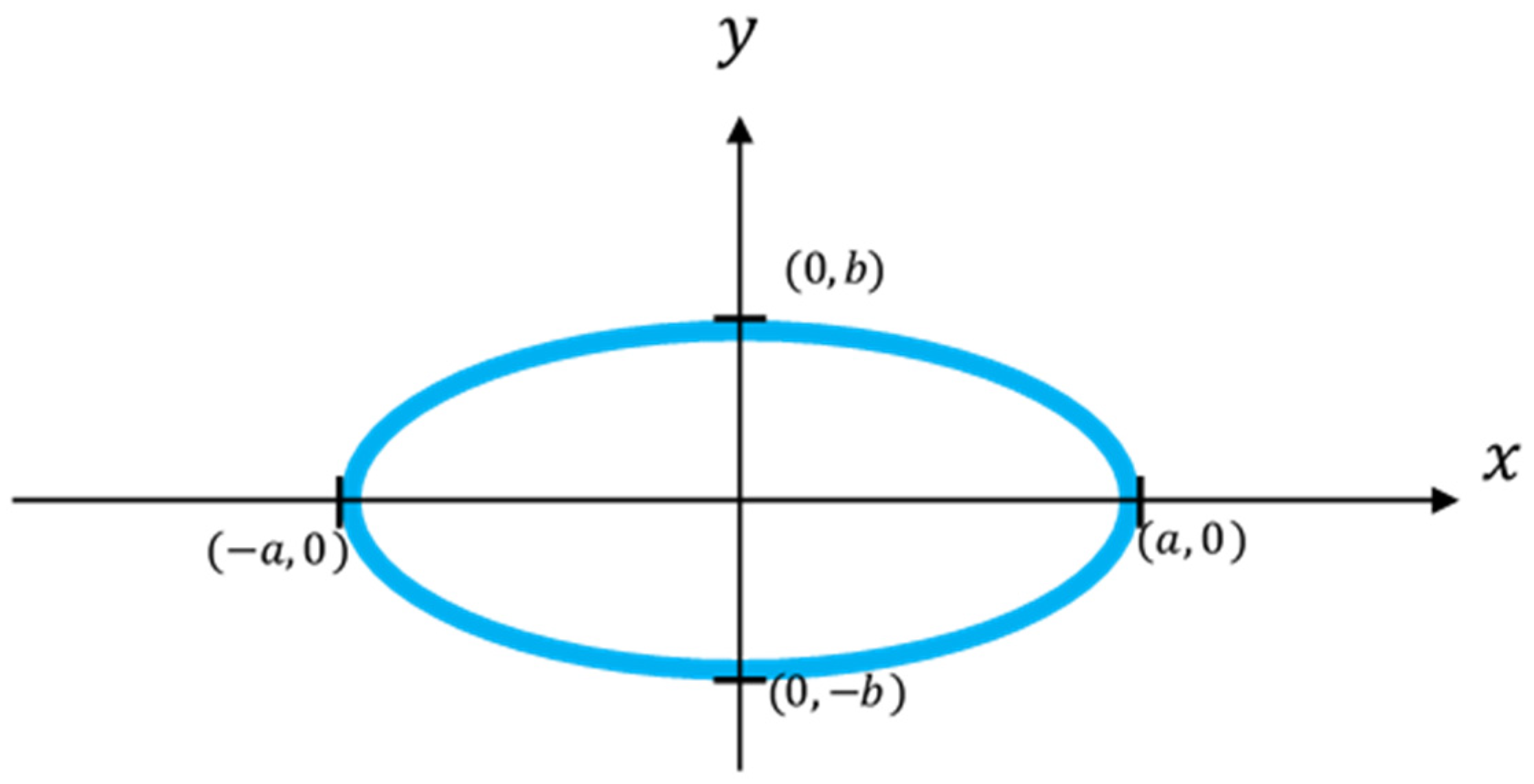
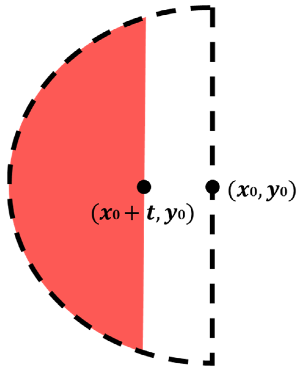
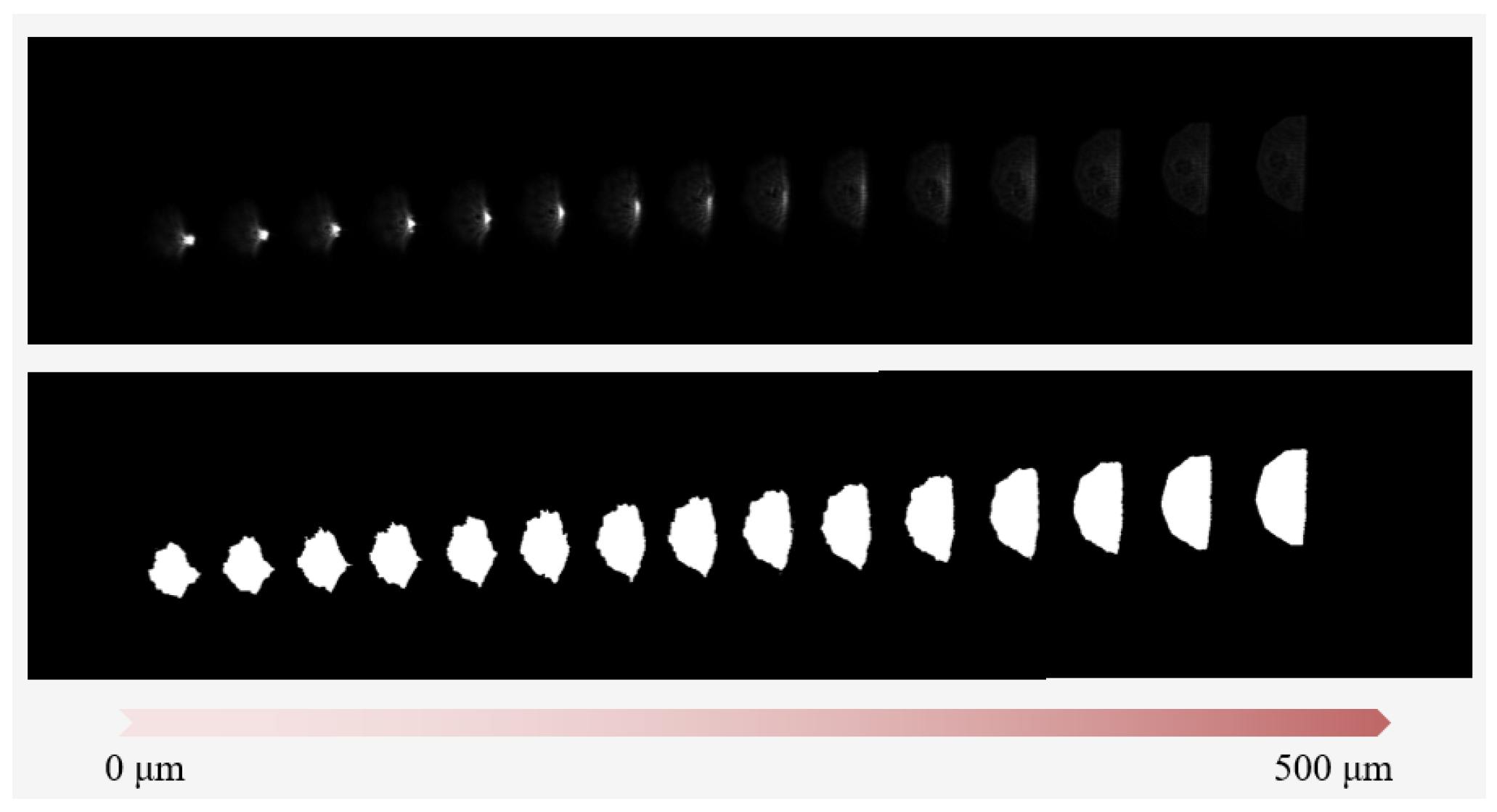
3.1. Proposed Ellipse Spot Compensation Algorithm

In an ideal case, the adopted autofocusing microscope conventionally utilized a knife (see Figure 2) to produce a reflective semicircular laser spot to measure the defocus direction and distance δ. However, in the real case, the captured laser spot image is likely an ellipse and not an ideal semicircular geometry. The ellipse shape may be caused by assembly errors of the instrument, variable reflection characteristics, or a tilt of the sample, and so on [40]. Consequently, an ellipse spot compensation algorithm is presented in this study, which uses the boundary information of the original laser spot image captured by CCD1 to efficiently overcome this issue.
First, according to the definition of Figure 6 and the ellipse’s equation, the equation of the left and right semicircles is obtained as:
x = ± a b b 2 y 2
Assume that an original laser spot image captured by CCD1 is shown in the red part of Figure 7; thus the midpoint of its chord is (x0 + t, y0), the ideal semi-ellipse is the black dashed part in Figure 7, and its geometrical center is (x0, y0). Taking the geometrical center of the ellipse into Equation (1), Equation (2) can be obtained:
x 0 = ± a b b 2 y 0 2
Take two points (x1, y1) and (x2, y2) of any asymmetric points on the arc of the captured laser spot image, and put them into Equation (2) and solve the equations to obtain a and b:
a = ( x 2 y 1 ) 2 ( x 1 y 2 ) 2 y 1 2 y 2 2
b = ( x 1 y 2 + x 2 y 1 ) ( x 1 y 2 x 2 y 1 ) ( x 1 + x 2 ) ( x 1 x 2 )
From Equations (1)–(4), the ellipse equations can be used to solve for the geometric center position. Finally, the centroid of the laser spot image can be obtained through the built-in function of LabView. Finally, the distance L between the centroid and geometric center of the captured laser spot image on CCD1 was obtained. Figure 8 illustrates the calculated and measured results for the distance L of the image with the defocus distance by using the proposed ellipse spot compensation algorithm. Using the measurement results, it has been determined that the linearity (R2) of the proposed distance L vs. defocus distance curve is approximately 91.77%, which is not in good agreement with the simulation results [16]. It can be found that this curve has multiple sets of different defocus distances corresponding to the same distance L. It is contributed to geometric laser beam variations or fluctuations. Therefore, as stated in the following section, the effects of laser fluctuations could be suppressed by using the proposed data compensation algorithm.

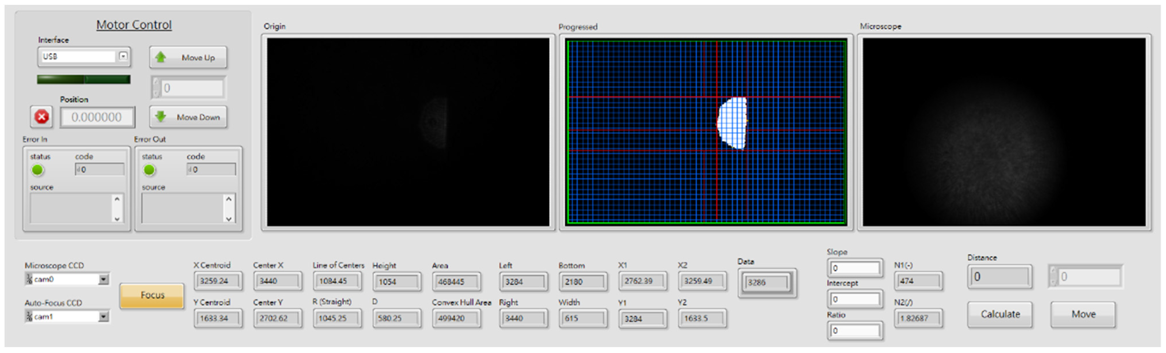
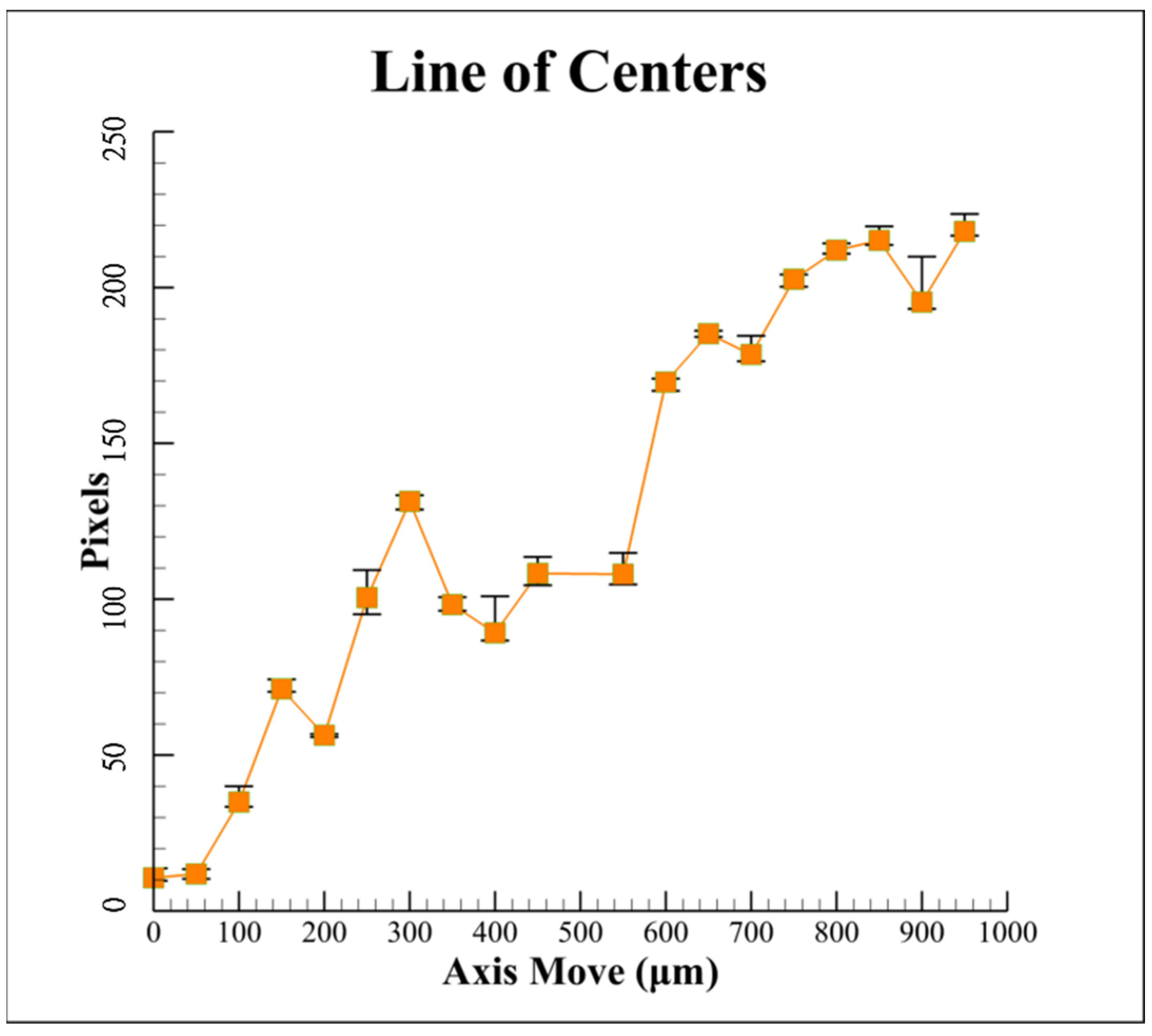
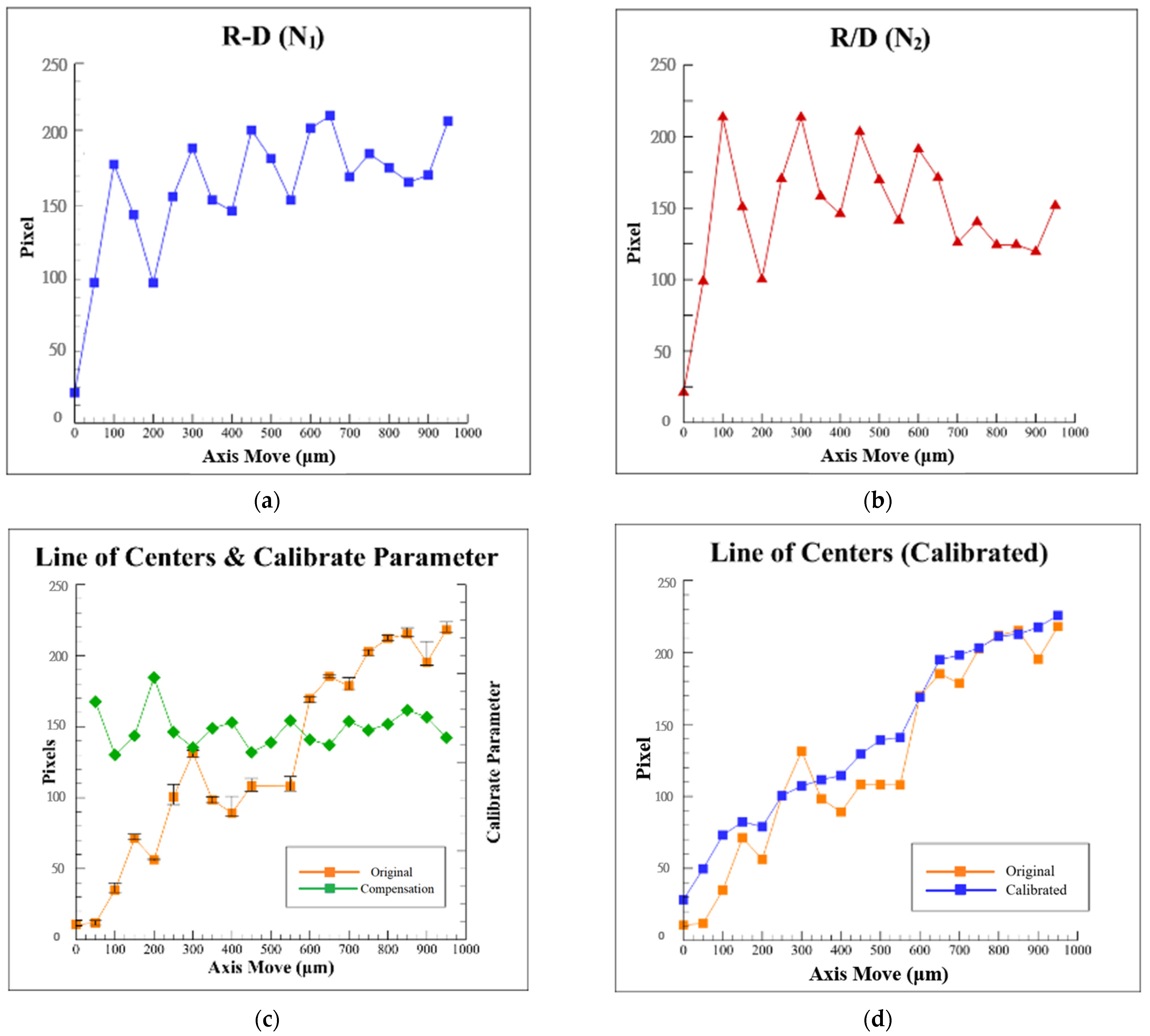
3.2. Proposed Data Compensation Algorithm

Optics-based autofocusing microscopes are often used for the measurements at the micrometer level. Therefore, small noises may cause large errors in the measurement results, for example, just like the results of Figure 8. The causes of the errors are usually laser disturbance and environmental factors. The most direct way to obtain the interference of various errors on the laser spot image is to start with the laser spot image itself. Any external noise will cause the “shape” of the spot image to change. Therefore, possible relationships can be found from analyzing the geometry of the captured laser spot image and the geometric laser beam variations or fluctuations.
First, we define the width and the height of the laser spot image as D and R, respectively, as shown in Figure 9.
Then we define N 1 = R D ,     N 2 = R D , divide N2 by N1, and multiply it by the corresponding value of the distance L to get the compensation value. These measurement results obtained for the variation of N1, N2, and N2/N1 with the defocus distance are illustrated in Figure 10a–c, respectively. Comparing these three curves in Figure 8 and Figure 10a,b, it can be found that the trends of these three curves are similar, which is no help for finding a pattern. From Figure 10c, it can be found that the trends of the two curves are opposite. The higher value in the original distance L is, the lower N2/N1 value will be, and vice versa. So, it is inferred that this value of N2/N1 can be used as a compensation value for the original distance L of the captured images to suppress the effects of geometric laser beam variations or fluctuations computationally.
This phenomenon is a significant finding in this study. Consequently, the following deduction can be obtained:
Compensation   value   C = Original   distance   L × [ 1 + K × ( N 2 N 1 ) ]
where C is the compensation number, L is the original distance, K ∈ ℚ, ℚ is the rational number, and N 1 = R D ,   N 2 = R D , and is mostly between 1 and 6. The worse the original accuracy of the system is, the higher the value of K will be.
Therefore, after multiplying the value of N2/N1 by six and adding to the original distance L, the calibrated distance L of the laser spot images in Figure 10d can be obtained by using the proposed data compensation algorithm. A total of six times results were used through the trial-and-error method for receiving the best value of K.
If we compare the two curves in Figure 10d, it can be found that the linearity of the calibrated curve is significantly improved to 97.81% from 91.77%, and it has demonstrated the feasibility of the proposed data compensation algorithm.

4. Experimental Results of Proposed Algorithm

As presented in Figure 4, to demonstrate the practical feasibility of the proposed algorithm, two sets of autofocusing experiments were carried out and compared using the proposed algorithm and the original distance L method [34], respectively, with different defocus distances δ (axis move). Figure 11 presents the experimental results for the autofocusing accuracy relative to the defocus distance δ (axis move), respectively. The original experimental results which are uncompensated have large errors and variations; however, the calibrated experimental results show the absolute value of the errors is about 1.5 to 2 μm. It is obvious that the autofocusing accuracy can be improved significantly by using the proposed algorithm.
As a means of comparing the conventional autofocusing microscope with the fair standards, the experiments in this study were conducted by using the same design parameters in [2]. Figure 12 shows experimental original and processed images of the laser spot on CCD1 for different defocus distances, respectively. The flowchart of the image processing in this study can be referred to our previous study [34]. It is noted that the real laser spot images are not a perfect semicircular, just like a semielliptical. Moreover, it can be found that the laser spot image has serious distortion near the in-focus position, so the original distance L method [34] cannot work well here.
Figure 13 illustrates the experimental autofocusing accuracy based on the proposed algorithm with different defocus distances δ (axis move). A total of five experiments were conducted for each defocus distance. As shown, the autofocusing accuracy by using the proposed algorithm can be improved to ≤1.5 μm, for which the range of average errors is between 0.5 μm and −1 μm and is better than that (≤2 μm) of the developed method by the rotating optical diffuser in [2]. In addition, the proposed algorithm does not add the hardware cost. In other words, the proposed algorithm for optics-based autofocusing microscopes can effectively improve the autofocusing accuracy and provides a promising method for suppressing geometric laser beam variations or fluctuations.

5. Conclusions

This present study has developed a set of algorithms that can quickly calculate the ideal ellipse center of the spot and effectively compensate the linearity of the focusing characteristic curve and has proposed a data compensation algorithm to improve the autofocusing accuracy and speed of the optics-based autofocusing microscope. By using a compensation value of the proposed algorithm, the variation of the image centroid position caused by geometric fluctuations of the laser beam is reduced. A prototype model has been constructed to assess the performance of the proposed algorithm.
According to the experimental results, the proposed algorithm has a higher accuracy of less than 1.5 μm when compared with the previous methods in [2] and [34]. Furthermore, the proposed method adds no other equipment to the system, which keep the system simple and saves the cost.
By reviewing the whole work presented in this present study, the contributions are concluded as follows:
  • Calculating the center position of the ideal ellipse through the boundary of the light spot can improve the accuracy of the defocus distance calculation of the subsequent autofocus system.
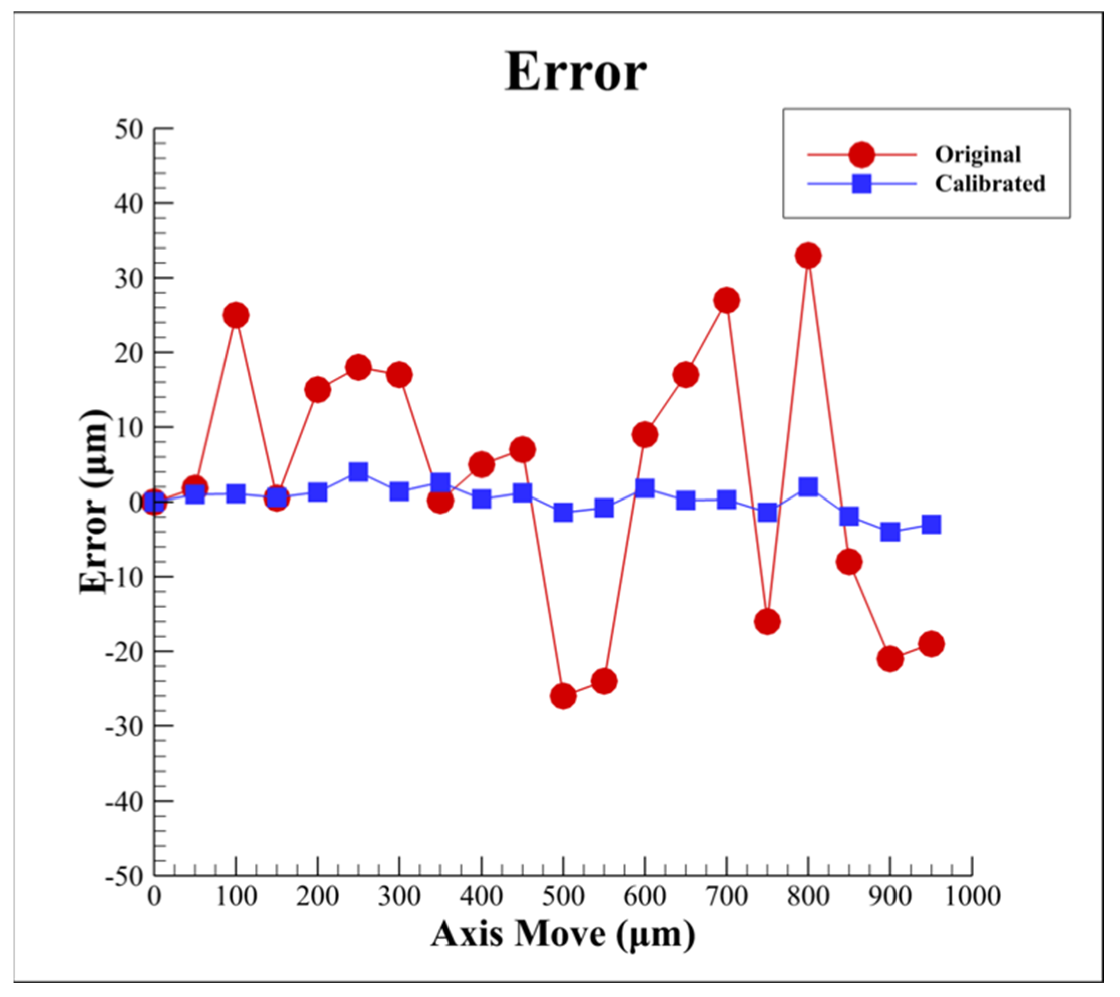
  • By using the proposed compensation algorithm, the linearity of the characteristic curve of the focusing system can be effectively improved, thereby achieving better accuracy of the optics-based autofocusing microscope.
  • The proposed innovative algorithm can effectively remove the noise interference caused by environmental factors such as laser disturbance, instruments, and air temperature to compensate the measurement data based on the current spot shape, which not only reduces the equipment cost but also improves the system efficiency.

Author Contributions

Conceptualization, C.-S.L. and H.-D.T.; methodology, H.-D.T.; software, H.-D.T.; validation, H.-D.T.; data curation, H.-D.T.; writing—original draft preparation, H.-D.T.; writing—review and editing, C.-S.L.; supervision, C.-S.L.; project administration, C.-S.L.; funding acquisition, C.-S.L. All authors have read and agreed to the published version of the manuscript.

Funding

This research was funded by the Ministry of Science and Technology of Taiwan, grant numbers MOST 110-2221-E-006-126-MY3 and 106-2628-E-006-010-MY3.

Institutional Review Board Statement

Not applicable.

Informed Consent Statement

Not applicable.

Data Availability Statement

Not applicable.

Acknowledgments

Ansys Inc. is thanked for providing ANSYS academic partner program.

Conflicts of Interest

The authors declare no conflict of interest.

References

  1. Petruck, P.; Riesenberg, R.; Kowarschik, R. Optimized coherence parameters for high-resolution holographic microscopy. Appl. Phys. A 2012, 106, 339–348. [Google Scholar] [CrossRef]
  2. Liu, C.-S.; Jiang, S.-H. Precise autofocusing microscope with rapid response. Opt. Lasers Eng. 2015, 66, 294–300. [Google Scholar] [CrossRef]
  3. Wang, F.; Cao, P.; Zhang, Y.; Hu, H.; Yang, Y. A Machine Vision Method for Correction of Eccentric Error Based on Adaptive Enhancement Algorithm. IEEE Trans. Instrum. Meas. 2021, 70, 5002311. [Google Scholar] [CrossRef]
  4. Luo, Y.; Huang, L.; Rivenson, Y.; Ozcan, A. Single-Shot Autofocusing of Microscopy Images Using Deep Learning. ACS Photon. 2021, 8, 625–638. [Google Scholar] [CrossRef]
  5. Kreft, M.; Stenovec, M.; Zorec, R. Focus-Drift Correction in Time-Lapse Confocal Imaging. Ann. N. Y. Acad. Sci. 2005, 1048, 321–330. [Google Scholar] [CrossRef]
  6. Chang, H.-C.; Shih, T.-M.; Zu Chen, N.; Pu, N.-W. A microscope system based on bevel-axial method auto-focus. Opt. Lasers Eng. 2009, 47, 547–551. [Google Scholar] [CrossRef]
  7. Lamadie, F.; Bruel, L.; Himbert, M. Digital holographic measurement of liquid–liquid two-phase flows. Opt. Lasers Eng. 2012, 50, 1716–1725. [Google Scholar] [CrossRef]
  8. Xu, S.-J.; Duan, Y.-Z.; Yu, Y.-H.; Tian, Z.-N.; Chen, Q.-D. Machine vision-based high-precision and robust focus detection for femtosecond laser machining. Opt. Express 2021, 29, 30952–30960. [Google Scholar] [CrossRef]
  9. Liu, C.-S.; Wang, Z.-Y.; Chang, Y.-C. Design and characterization of high-performance autofocusing microscope with zoom in/out functions. Appl. Phys. A 2015, 121, 69–80. [Google Scholar] [CrossRef]
  10. Jan, C.-M.; Liu, C.-S.; Yang, J.-Y. Implementation and Optimization of a Dual-confocal Autofocusing System. Sensors 2020, 20, 3479. [Google Scholar] [CrossRef]
  11. Fujishiro, Y.; Furukawa, T.; Maruo, S. Simple autofocusing method by image processing using transmission images for large-scale two-photon lithography. Opt. Express 2020, 28, 12342–12351. [Google Scholar] [CrossRef] [PubMed]
  12. Liu, C.-S.; Song, R.-C.; Fu, S.-J. Design of a laser-based autofocusing microscope for a sample with a transparent boundary layer. Appl. Phys. A 2019, 125, 199. [Google Scholar] [CrossRef]
  13. Bezzubik, V.V.; Ustinov, S.N.; Belashenkov, N.R. Optimization of algorithms for autofocusing a digital microscope. J. Opt. Technol. 2009, 76, 603–608. [Google Scholar] [CrossRef]
  14. Hsu, W.-Y.; Lee, C.-S.; Chen, P.-J.; Chen, N.-T.; Chen, F.-Z.; Yu, Z.-R.; Kuo, C.-H.; Hwang, C.-H. Development of the fast astigmatic auto-focus microscope system. Meas. Sci. Technol. 2009, 20, 045902. [Google Scholar] [CrossRef]
  15. Chen, C.-Y.; Hwang, R.-C.; Chen, Y.-J. A passive auto-focus camera control system. Appl. Soft Comput. 2010, 10, 296–303. [Google Scholar] [CrossRef]
  16. Liu, C.-S.; Hu, P.-H.; Lin, Y.-C. Design and experimental validation of novel optics-based autofocusing microscope. Appl. Phys. A 2012, 109, 259–268. [Google Scholar] [CrossRef]
  17. Zhang, X.; Fan, F.; Gheisari, M.; Srivastava, G. A Novel Auto-Focus Method for Image Processing Using Laser Triangulation. IEEE Access 2019, 7, 64837–64843. [Google Scholar] [CrossRef]
  18. Kia, M.M.M.; Alzubi, J.A.; Gheisari, M.; Zhang, X.; Rahimi, M.; Qin, Y. A Novel Method for Recognition of Persian Alphabet by Using Fuzzy Neural Network. IEEE Access 2018, 6, 77265–77271. [Google Scholar]
  19. Strzecha, K.; Koszmider, T.; Zarębski, D.; Łobodziński, W. Passive Auto-Focus Algorithm for Correcting Image Distortions Caused by Gas Flow in High-Temperature Measurements of Surface Phenomena. Image Process. Commun. 2012, 17, 379–384. [Google Scholar] [CrossRef] [Green Version]
  20. Dastidar, T.R.; Ethirajan, R. Whole slide imaging system using deep learning-based automated focusing. Biomed. Opt. Express 2020, 11, 480–491. [Google Scholar] [CrossRef]
  21. Pengo, T.; Muñoz-Barrutia, A.; Ortiz-De-Solórzano, C. Halton sampling for autofocus. J. Microsc. 2009, 235, 50–58. [Google Scholar] [CrossRef] [PubMed]
  22. Hedde, P.N.; Gratton, E. Active focus stabilization for upright selective plane illumination microscopy. Opt. Express 2015, 23, 14707–14714. [Google Scholar] [CrossRef] [PubMed] [Green Version]
  23. Peng, G.-J.; Yu, Z.-M.; Yu, J.-H. Auto-focus windows selection algorithm for optical microscope. J. Appl. Opt. 2015, 36, 550–558. [Google Scholar]
  24. Selami, Y.; Tao, W.; Gao, Q.; Yang, H.; Zhao, H. A Scheme for Enhancing Precision in 3-Dimensional Positioning for Non-Contact Measurement Systems Based on Laser Triangulation. Sensors 2018, 18, 504. [Google Scholar] [CrossRef] [PubMed] [Green Version]
  25. Guo, C.; Bian, Z.; Alhudaithy, S.; Jiang, S.; Tomizawa, Y.; Song, P.; Wang, T.; Shao, X. Brightfield, fluorescence, and phase-contrast whole slide imaging via dual-LED autofocusing. Biomed. Opt. Express 2021, 12, 4651–4660. [Google Scholar] [CrossRef] [PubMed]
  26. Wu, S.-Q.; Shen, B.; Wang, J.-H.; Zheng, D.-T.; Fleischer, J. Superresolution algorithm for laser triangulation measurement. Lasers Eng. 2017, 8, 385–395. [Google Scholar]
  27. Fan, K.-C.; Chu, C.-L.; Mou, J.-I. Development of a low-cost autofocusing probe for profile measurement. Meas. Sci. Technol. 2001, 12, 2137–2146. [Google Scholar] [CrossRef]
  28. Jung, B.J.; Kong, H.J.; Jeon, B.G.; Yang, D.-Y.; Son, Y.; Lee, K.-S. Autofocusing method using fluorescence detection for precise two-photon nanofabrication. Opt. Express 2011, 19, 22659–22668. [Google Scholar] [CrossRef] [Green Version]
  29. Wang, Y.; Kuang, C.; Xiu, P.; Li, S.; Hao, X.; Liu, X. A lateral differential confocal microscopy for accurate detection and localization of edge contours. Opt. Lasers Eng. 2013, 53, 12–18. [Google Scholar] [CrossRef]
  30. Liu, C.-S.; Jiang, S.-H. Design and experimental validation of novel enhanced-performance autofocusing microscope. Appl. Phys. A 2014, 117, 1161–1171. [Google Scholar] [CrossRef]
  31. Pinkard, H.; Phillips, Z.; Babakhani, A.; Fletcher, D.A.; Waller, L. Deep learning for single-shot autofocus microscopy. Optica 2019, 6, 794–797. [Google Scholar] [CrossRef]
  32. Yao, S.; Li, H.; Pang, S.; Zhu, B.; Zhang, X.; Fatikow, S. A Review of Computer Microvision-Based Precision Motion Measurement: Principles, Characteristics, and Applications. IEEE Trans. Instrum. Meas. 2021, 70, 5007928. [Google Scholar] [CrossRef]
  33. Weiss, A.; Obotnine, A.; Lasinski, A. Method and Apparatus for the Auto-Focusing Infinity Corrected Microscopes. U.S. Patent 7700903, 20 April 2010. [Google Scholar]
  34. Liu, C.-S.; Lin, Y.-C.; Hu, P.-H. Design and characterization of precise laser-based autofocusing microscope with reduced geometrical fluctuations. Microsyst. Technol. 2013, 19, 1717–1724. [Google Scholar] [CrossRef]
  35. Wang, S.H.; Tay, C.J.; Quan, C.; Shang, H.M.; Zhou, Z.F. Laser integrated measurement of surface roughness and micro-displacement. Meas. Sci. Technol. 2000, 11, 454–458. [Google Scholar] [CrossRef]
  36. Rodwell, M.J.W.; Baer, T.; Kolner, B.H.; Weingarten, K.J.; Bloom, D.M. Reduction of timing fluctuations in a mode-locked Nd:YAG laser by electronic feedback. Opt. Lett. 1986, 11, 638–640. [Google Scholar] [CrossRef]
  37. Andronova, I.A.; Bershtein, I.L. Suppression of fluctuations of the intensity of radiation emitted by semiconductor lasers. Sov. J. Quantum Electron. 1991, 21, 616–618. [Google Scholar] [CrossRef]
  38. Liu, C.-S.; Jiang, S.-H. A novel laser displacement sensor with improved robustness toward geometrical fluctuations of the laser beam. Meas. Sci. Technol. 2013, 24, 105101-1–105101-8. [Google Scholar] [CrossRef]
  39. Liu, C.-S.; Lin, K.-W. Numerical and experimental characterization of reducing geometrical fluctuations of laser beam based on rotating optical diffuser. Opt. Eng. 2014, 53, 122408. [Google Scholar] [CrossRef]
  40. Hsu, W.-Y. Automatic Compensation for Defects of Laser Reflective Patterns in Optics-Based Auto-Focusing Microscopes. IEEE Sens. J. 2020, 20, 2034–2044. [Google Scholar] [CrossRef]
Figure 1. Definition of L between centroid and geometric center of captured laser spot images.
Sensors 22 05058 g001
Figure 2. Structure of adopted autofocusing microscope.
Sensors 22 05058 g002
Figure 3. Relation between L and defocus distance δ.
Sensors 22 05058 g003
Figure 4. (a) Photograph of laboratory-built prototype; (b) infinity-corrected optics system part.
Sensors 22 05058 g004
Figure 5. Proposed HMI.
Sensors 22 05058 g005
Figure 6. An ellipse centered at the origin.
Sensors 22 05058 g006
Figure 7. Compensation of ellipse spot image.
Sensors 22 05058 g007
Figure 8. Measurement results of proposed algorithm for variation of distance L between centroid and geometric center with defocus distance.
Sensors 22 05058 g008
Figure 9. Definition of width D and height R for laser spot image.
Sensors 22 05058 g009
Figure 10. Measurement results of the proposed algorithm: variation of (a) value of R-D, (b) value of R/D, (c) compensation value, and (d) calibrated value with defocus distance, respectively.
Sensors 22 05058 g010
Figure 11. Experimental results for autofocusing accuracy with different defocus distances by using proposed algorithm and original distance L method, respectively.
Sensors 22 05058 g011
Figure 12. Experimental original and processed laser spot images on CCD1 with different defocus distances, respectively. The top one is original and the bottom one is processed.
Sensors 22 05058 g012
Figure 13. Experimental results for autofocusing accuracy with different defocus distances by using proposed algorithm.
Sensors 22 05058 g013
Table 1. Design parameters of proposed autofocusing microscope.
VariableBrandModel
LaserThorlabsHL6501MG
Beam SplitterThorlabsBSW29 (50:50)
Biconvex LensThorlabsUB1945K
45° Red Dichroic FilterEdmundPBSW-633R
SampleThorlabsMirror
Objective LensOlympusf0 = 18 mm
CCD1, CCD2Basler5472 px × 3648 px, 17 fps
Infinity-Corrected Optics SystemNavita1-60255
MotorPIUPL120 stroke of 13 mm
Publisher’s Note: MDPI stays neutral with regard to jurisdictional claims in published maps and institutional affiliations.

