
Graph Optimization Model Fusing BLE Ranging with Wi-Fi Fingerprint for Indoor Positioning


Abstract
:1. Introduction
2. Related Work
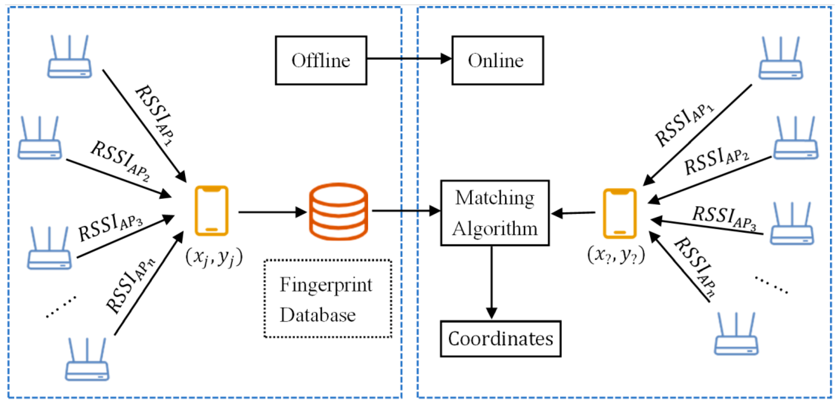
2.1. Wi-Fi Fingerprint Positioning
2.2. Signal Propagation of BLE
2.3. Graph Optimization Based on o
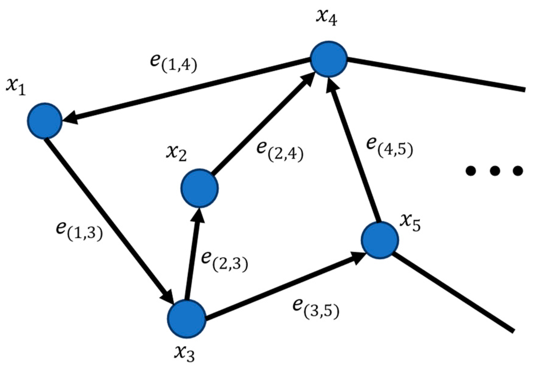
3. Proposed Graph Optimization Model
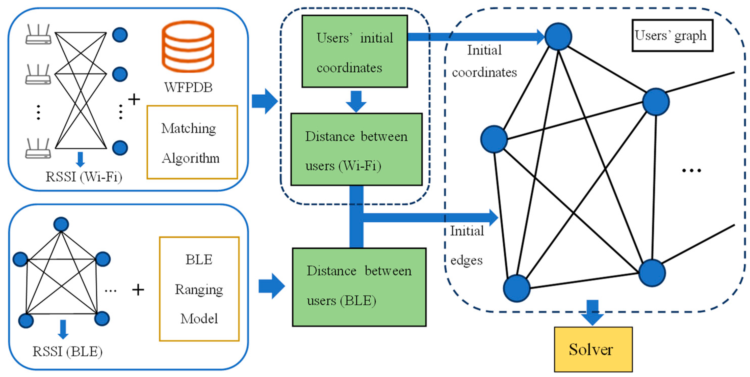
3.1. Model Overview
3.2. Construction and Solution of Total Error Function
| Algorithm 1: Pseudo code of LM algorithm |
| Input: A total error function FH(p) and an initial vector pw Output: A vector p* minimizing FH(p) 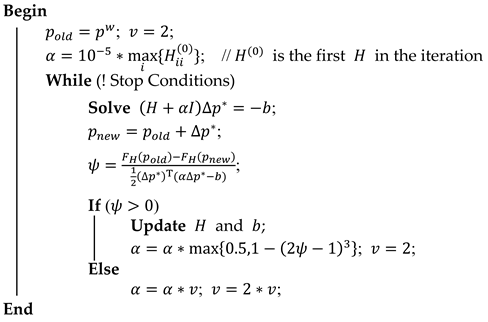 |
3.3. Drifting Solution Based on Affine Transformation Estimation
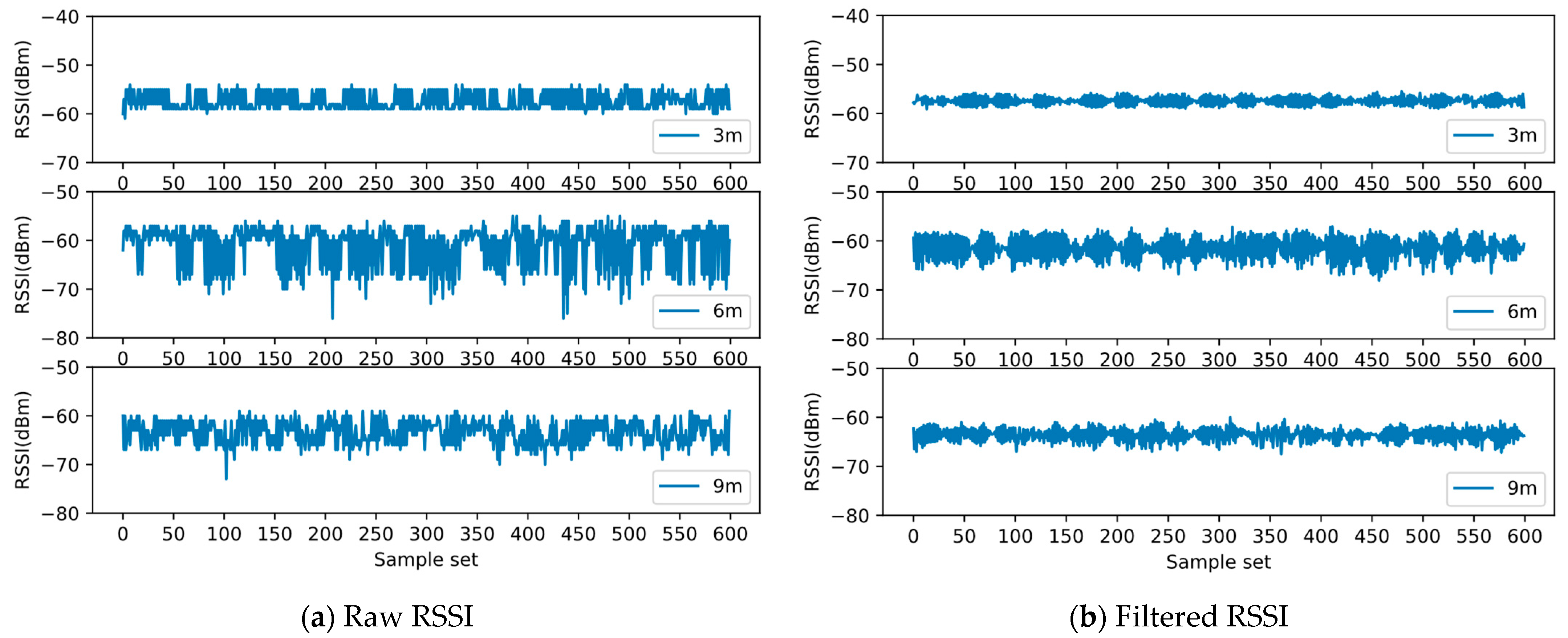
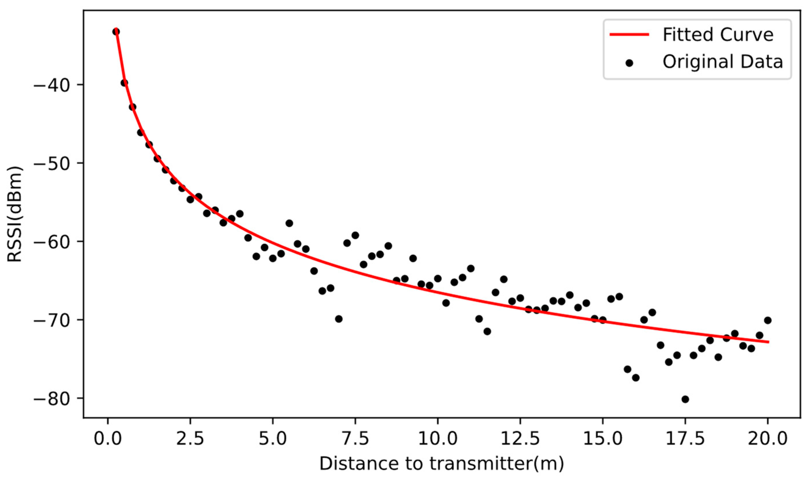
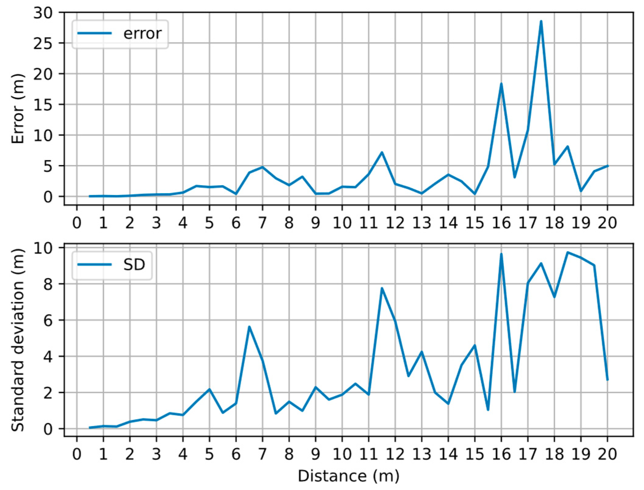
3.4. BLE Signal Filter and Ranging Model
4. Experiments
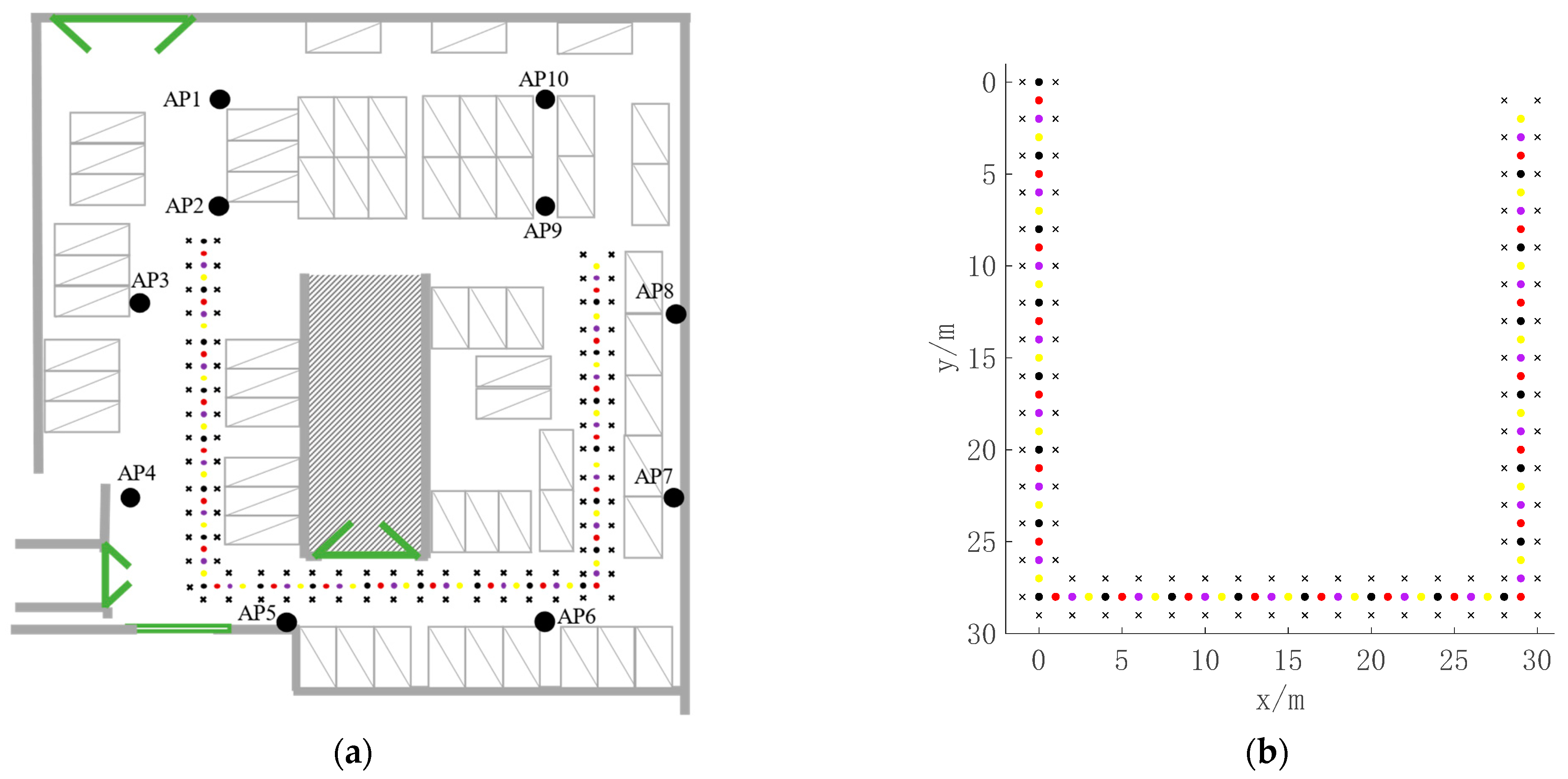
4.1. Experimental Environment
4.2. Edge Selection
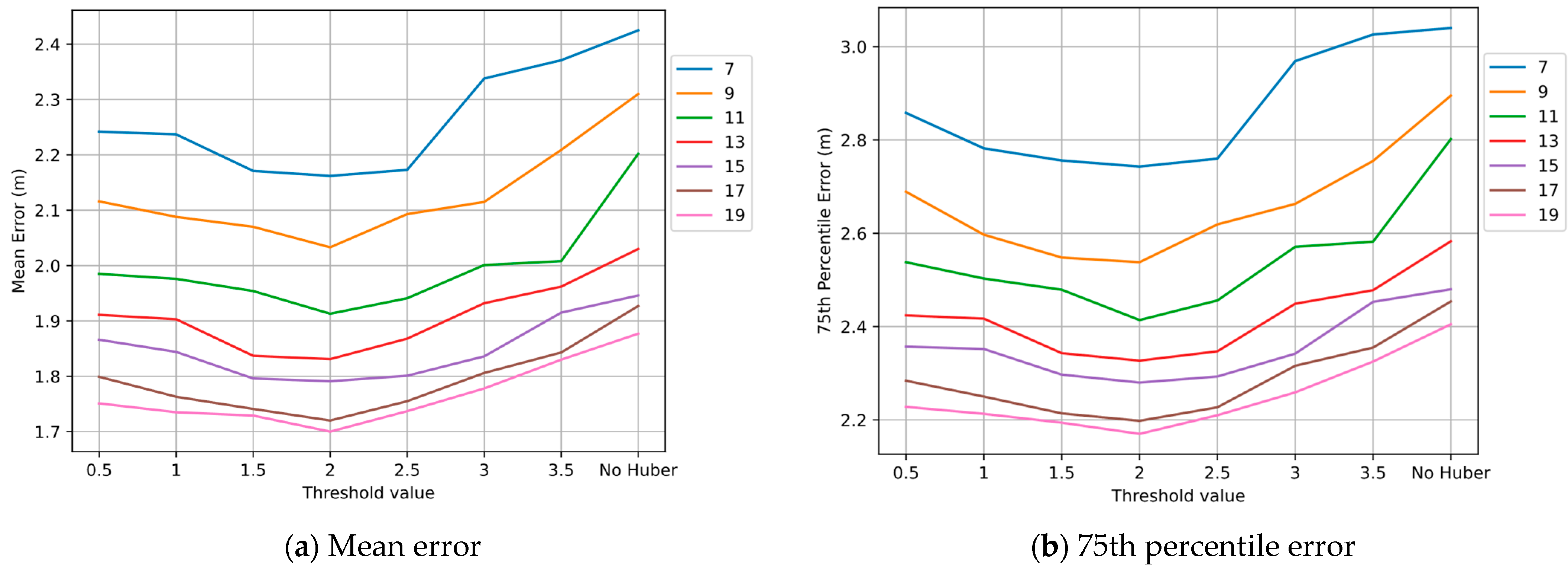
4.3. Influence of Threshold in Huber Kernel Function
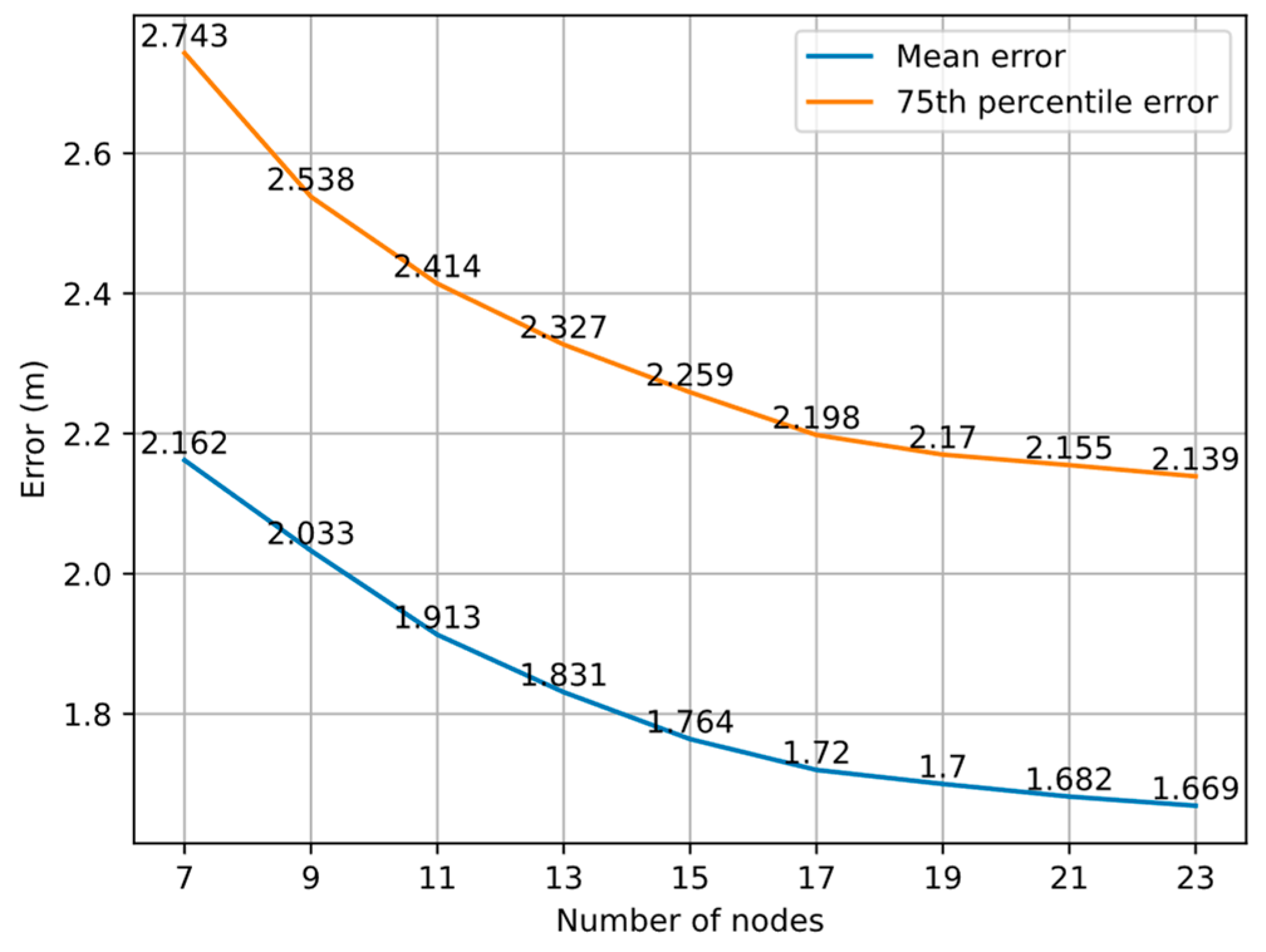
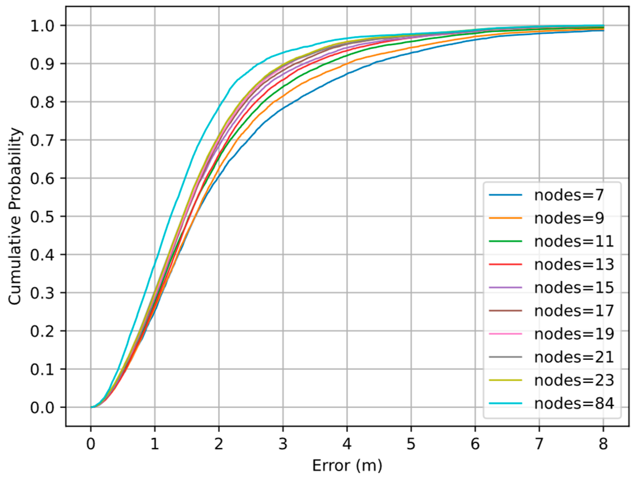
4.4. Impact of Number of Nodes in Graph
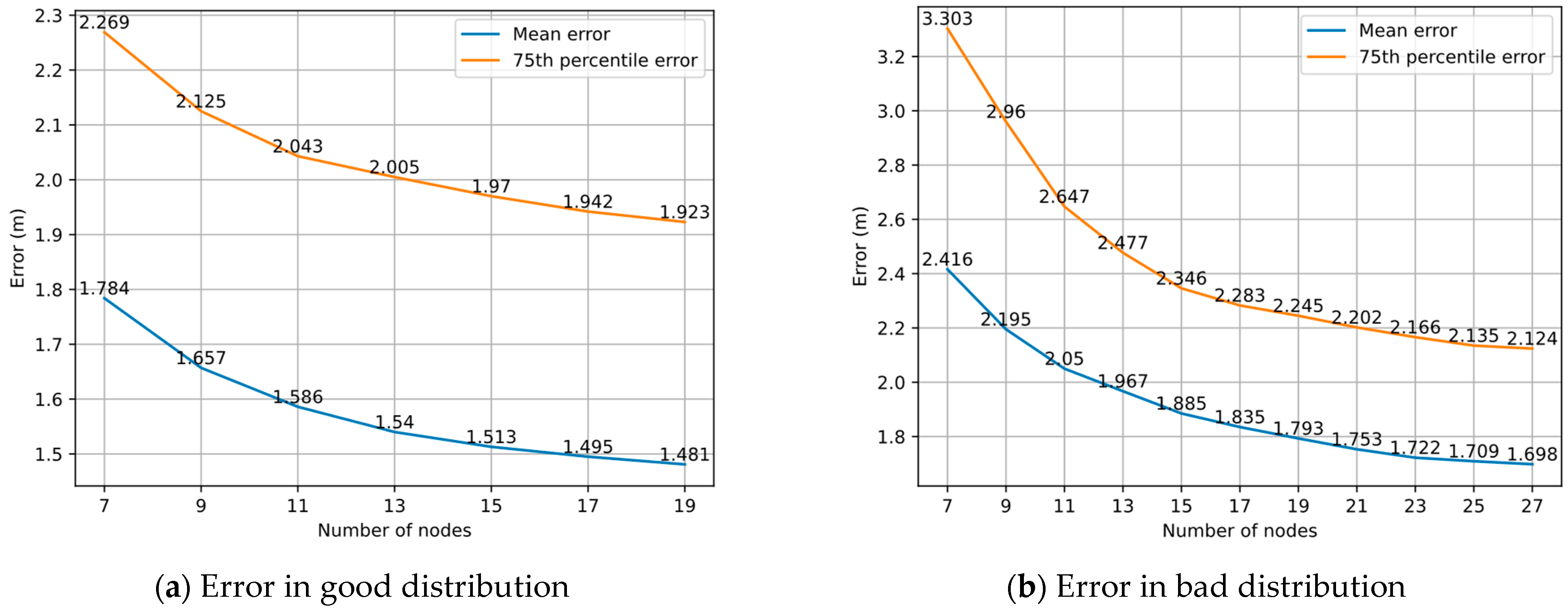
4.5. Impact of Distribution of Nodes in Graph
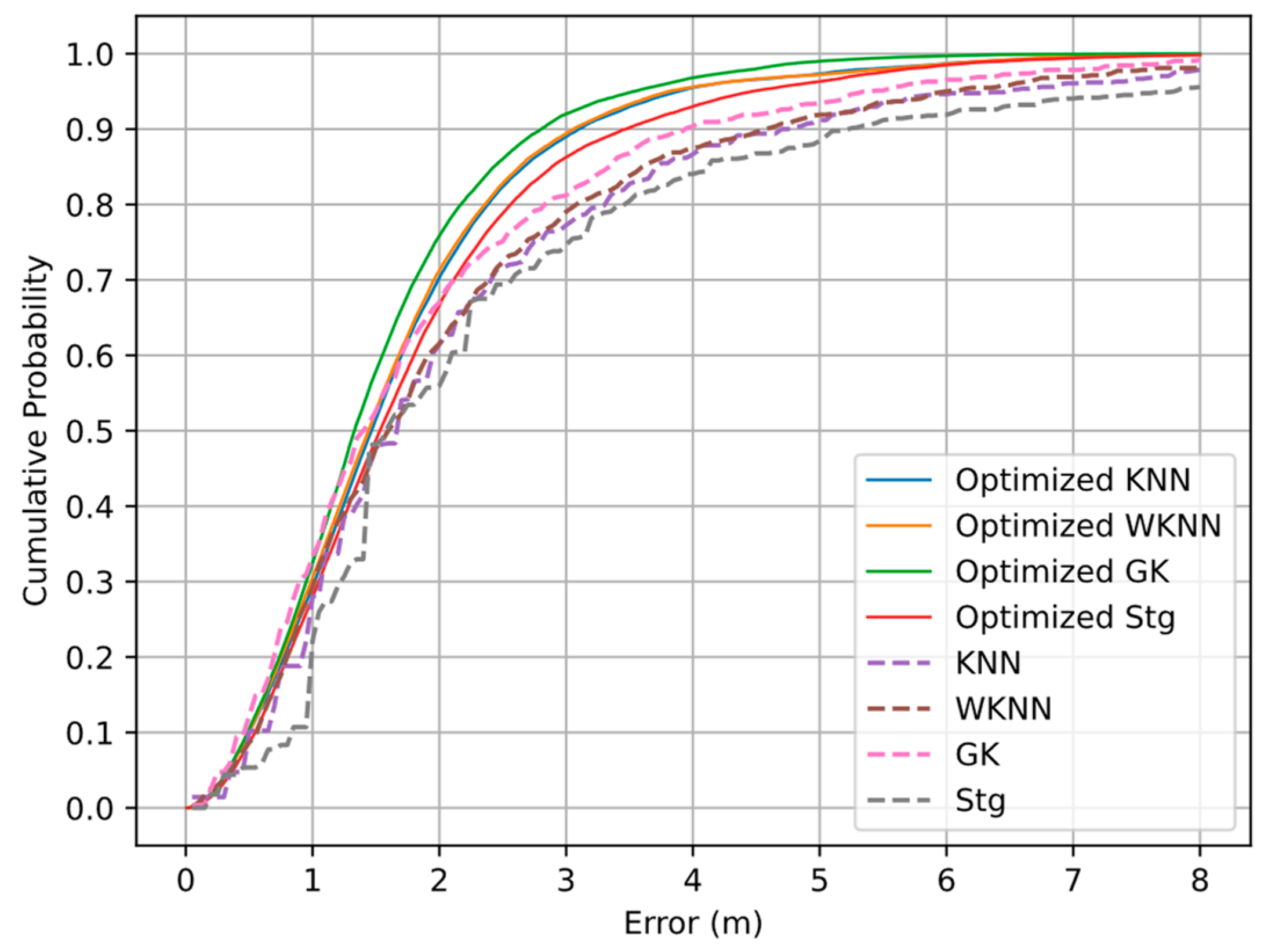
4.6. Comparison of Wi-Fi Fingerprint-Matching Algorithms after Optimization
5. Conclusions and Further Work
Author Contributions
Funding
Institutional Review Board Statement
Informed Consent Statement
Data Availability Statement
Conflicts of Interest
References
- Wei, X.; Wei, Z.; Radu, V. Sensor-Fusion for Smartphone Location Tracking Using Hybrid Multimodal Deep Neural Networks. Sensors 2021, 21, 7488. [Google Scholar] [CrossRef] [PubMed]
- Jo, H.J.; Kim, S. Indoor Smartphone Localization Based on LOS and NLOS Identification. Sensors 2018, 18, 3987. [Google Scholar] [CrossRef] [PubMed] [Green Version]
- Zhou, R.; Yang, Y.; Chen, P. An RSS Transform–Based WKNN for Indoor Positioning. Sensors 2021, 21, 5685. [Google Scholar] [CrossRef]
- Ramirez, R.; Huang, C.-Y.; Liao, C.-A.; Lin, P.-T.; Lin, H.-W.; Liang, S.-H. A Practice of BLE RSSI Measurement for Indoor Positioning. Sensors 2021, 21, 5181. [Google Scholar] [CrossRef] [PubMed]
- Bottigliero, S.; Milanesio, D.; Saccani, M.; Maggiora, R. A Low-Cost Indoor Real-Time Locating System Based on TDOA Estimation of UWB Pulse Sequences. IEEE Trans. Instrum. Meas. 2021, 70, 1–11. [Google Scholar] [CrossRef]
- Makki, A.; Siddig, A.; Bleakley, C.J. Robust High Resolution Time of Arrival Estimation for Indoor WLAN Ranging. IEEE Trans. Instrum. Meas. 2017, 66, 2703–2710. [Google Scholar] [CrossRef]
- Yang, T.; Cabani, A.; Chafouk, H. A Survey of Recent Indoor Localization Scenarios and Methodologies. Sensors 2021, 21, 8086. [Google Scholar] [CrossRef]
- Zhou, M.; Lin, Y.; Zhao, N.; Jiang, Q.; Yang, X.; Tian, Z. Indoor WLAN Intelligent Target Intrusion Sensing Using Ray-Aided Generative Adversarial Network. IEEE Trans. Emerg. Top. Comput. Intell. 2020, 4, 61–73. [Google Scholar] [CrossRef]
- Sugasaki, M.; Shimosaka, M. Robustifying Wi-Fi Localization by Between-Location Data Augmentation. IEEE Sens. J. 2022, 22, 5407–5416. [Google Scholar] [CrossRef]
- He, S.; Chan, S.G. Wi-Fi Fingerprint-Based Indoor Positioning: Recent Advances and Comparisons. IEEE Commun. Surv. Tutor. 2016, 18, 466–490. [Google Scholar] [CrossRef]
- Zafari, F.; Papapanagiotou, I.; Christidis, K. Microlocation for Internet-of-Things-Equipped Smart Buildings. IEEE Internet Things J. 2016, 3, 96–112. [Google Scholar] [CrossRef] [Green Version]
- Takahashi, C.; Kondo, K. Indoor positioning method for augmented audio reality navigation systems using iBeacons. In Proceedings of the 2015 IEEE 4th Global Conference on Consumer Electronics (GCCE), Osaka, Japan, 27–30 October 2015; pp. 451–452. [Google Scholar]
- Liu, W.; Guo, W.; Zhu, X. Map-Aided Indoor Positioning Algorithm with Complex Deployed BLE Beacons. ISPRS Int. J. Geo-Inf. 2021, 10, 526. [Google Scholar] [CrossRef]
- Bahl, P.; Padmanabhan, V.N. RADAR: An in-building RF-based user location and tracking system. In Proceedings of the IEEE INFOCOM 2000, Conference on Computer Communications, Nineteenth Annual Joint Conference of the IEEE Computer and Communications Societies (Cat. No.00CH37064), Tel Aviv, Israel, 26–30 March 2000; Volume 772, pp. 775–784. [Google Scholar]
- Castro, P.; Chiu, P.; Kremenek, T.; Muntz, R. A Probabilistic Room Location Service for Wireless Networked Environments. In Proceedings of the Ubicomp 2001 Conference, Atlanta, GA, USA, 30 September–2 October 2001; Springer: Berlin/Heidelberg, Germany, 2001; pp. 18–34. [Google Scholar]
- Youssef, M.; Agrawala, A. The Horus location determination system. Wirel. Netw. 2008, 14, 357–374. [Google Scholar] [CrossRef]
- Ferreira, D.; Souza, R.; Carvalho, C. QA-kNN: Indoor Localization Based on Quartile Analysis and the kNN Classifier for Wireless Networks. Sensors 2020, 20, 4714. [Google Scholar] [CrossRef] [PubMed]
- Siyang, L.I.U.; De Lacerda, R.; Fiorina, J. WKNN indoor Wi-Fi localization method using k-means clustering based radio mapping. In Proceedings of the 2021 IEEE 93rd Vehicular Technology Conference (VTC2021-Spring), Helsinki, Finland, 25–28 April 2021; pp. 1–5. [Google Scholar]
- Marques, N.; Meneses, F.; Moreira, A. Combining similarity functions and majority rules for multi-building, multi-floor, WiFi positioning. In Proceedings of the 2012 International Conference on Indoor Positioning and Indoor Navigation (IPIN), Sydney, Australia, 13–15 November 2012; pp. 1–9. [Google Scholar]
- Roos, T.; Myllymäki, P.; Tirri, H.; Misikangas, P.; Sievänen, J. A Probabilistic Approach to WLAN User Location Estimation. Int. J. Wirel. Inf. Netw. 2002, 9, 155–164. [Google Scholar] [CrossRef]
- Fang, S.; Lin, T. Indoor Location System Based on Discriminant-Adaptive Neural Network in IEEE 802.11 Environments. IEEE Trans. Neural Netw. 2008, 19, 1973–1978. [Google Scholar] [CrossRef]
- Wang, X.; Gao, L.; Mao, S.; Pandey, S. CSI-Based Fingerprinting for Indoor Localization: A Deep Learning Approach. IEEE Trans. Veh. Technol. 2017, 66, 763–776. [Google Scholar] [CrossRef] [Green Version]
- Golestani, A.; Petreska, N.; Wilfert, D.; Zimmer, C. Improving the precision of RSSI-based low-energy localization using path loss exponent estimation. In Proceedings of the 2014 11th Workshop on Positioning, Navigation and Communication (WPNC), Dresden, Germany, 12–13 March 2014; pp. 1–6. [Google Scholar]
- Nowak, T.; Hartmann, M.; Zech, T.; Thielecke, J. A path loss and fading model for RSSI-based localization in forested areas. In Proceedings of the 2016 IEEE-APS Topical Conference on Antennas and Propagation in Wireless Communications (APWC), Cairns, Australia, 19–23 September 2016; pp. 110–113. [Google Scholar]
- Nguyen, H.A.; Guo, H.; Low, K. Real-Time Estimation of Sensor Node’s Position Using Particle Swarm Optimization With Log-Barrier Constraint. IEEE Trans. Instrum. Meas. 2011, 60, 3619–3628. [Google Scholar] [CrossRef]
- Lee, G.; Moon, B.-C.; Lee, S.; Han, D. Fusion of the SLAM with Wi-Fi-Based Positioning Methods for Mobile Robot-Based Learning Data Collection, Localization, and Tracking in Indoor Spaces. Sensors 2020, 20, 5182. [Google Scholar] [CrossRef]
- Mur-Artal, R.; Montiel, J.M.M.; Tardós, J.D. ORB-SLAM: A Versatile and Accurate Monocular SLAM System. IEEE Trans. Robot. 2015, 31, 1147–1163. [Google Scholar] [CrossRef] [Green Version]
- Sun, C.Z.; Zhang, B.; Wang, J.K.; Zhang, C.S. A Review of Visual SLAM Based on Unmanned Systems. In Proceedings of the 2021 2nd International Conference on Artificial Intelligence and Education (ICAIE), Dali, China, 18–20 June 2021; pp. 226–234. [Google Scholar]
- Lourakis, M.L.A.; Argyros, A.A. Is Levenberg-Marquardt the most efficient optimization algorithm for implementing bundle adjustment? In Proceedings of the Tenth IEEE International Conference on Computer Vision (ICCV’05), Beijing, China, 17–21 October 2005; Volume 1, pp. 1526–1531. [Google Scholar]
- Kümmerle, R.; Grisetti, G.; Strasdat, H.; Konolige, K.; Burgard, W. G2o: A general framework for graph optimization. In Proceedings of the 2011 IEEE International Conference on Robotics and Automation, Shanghai, China, 9–13 May 2011; pp. 3607–3613. [Google Scholar]
- Jianyong, Z.; Haiyong, L.; Zili, C.; Zhaohui, L. RSSI based Bluetooth low energy indoor positioning. In Proceedings of the 2014 International Conference on Indoor Positioning and Indoor Navigation (IPIN), Busan, Korea, 27–30 October 2014; pp. 526–533. [Google Scholar]
- Balasundaram, S.; Meena, Y. Robust Support Vector Regression in Primal with Asymmetric Huber Loss. Neural Process. Lett. 2019, 49, 1399–1431. [Google Scholar] [CrossRef]


| Distance (m) | SD (Original RSSI) (dBm) | SD (Filtered RSSI) (dBm) |
|---|---|---|
| 3 | 1.802 | 0.935 |
| 6 | 4.553 | 2.594 |
| 9 | 2.542 | 1.498 |
| Distance (m) | Error (m) | Distance (m) | Error (m) |
|---|---|---|---|
| 1 | 0.058 | 9 | 0.448 |
| 2 | 0.104 | 10 | 1.573 |
| 3 | 0.308 | 11 | 3.623 |
| 4 | 0.615 | 12 | 2.02 |
| 5 | 1.518 | 13 | 0.487 |
| 6 | 0.413 | 14 | 3.538 |
| 7 | 4.761 | 15 | 0.419 |
| 8 | 1.829 |
| Algorithm | 1 m | 1.5 m | 2 m | 2.5 m | 3 m |
|---|---|---|---|---|---|
| Optimized KNN | 29.34% | 51.73% | 70.24% | 82.35% | 89.02% |
| Optimized WKNN | 30.47% | 52.72% | 71.27% | 82.79% | 89.44% |
| Optimized GK | 33.41% | 57.88% | 75.9% | 86.04% | 92.1% |
| Optimized Stg | 27.93% | 48.86% | 66.59% | 78.79% | 86.26% |
| KNN | 28.1% | 47.86% | 61.43% | 71.55% | 77.26% |
| WKNN | 29.29% | 47.74% | 61.55% | 72.38% | 79.05% |
| GK | 33.33% | 52.62% | 67.02% | 75.12% | 81.19% |
| Stg | 22.14% | 48.21% | 55.95% | 69.4% | 74.64% |
| Algorithm | Optimized KNN | Optimized WKNN | Optimized GK | Optimized Stg | KNN | WKNN | GK | Stg | |
|---|---|---|---|---|---|---|---|---|---|
| Indicator | |||||||||
| Mean Error (m) | 1.7 | 1.68 | 1.54 | 1.82 | 2.21 | 2.14 | 1.91 | 2.5 | |
| 75th Percentile Error (m) | 2.17 | 2.14 | 1.97 | 2.32 | 2.75 | 2.69 | 2.50 | 3.01 | |
| Error Std (m) | 1.19 | 1.18 | 1.01 | 1.3 | 1.92 | 1.85 | 1.67 | 2.33 | |
Publisher’s Note: MDPI stays neutral with regard to jurisdictional claims in published maps and institutional affiliations. |
© 2022 by the authors. Licensee MDPI, Basel, Switzerland. This article is an open access article distributed under the terms and conditions of the Creative Commons Attribution (CC BY) license (https://creativecommons.org/licenses/by/4.0/).
Share and Cite
Zhou, R.; Chen, P.; Teng, J.; Meng, F. Graph Optimization Model Fusing BLE Ranging with Wi-Fi Fingerprint for Indoor Positioning. Sensors 2022, 22, 4045. https://doi.org/10.3390/s22114045
Zhou R, Chen P, Teng J, Meng F. Graph Optimization Model Fusing BLE Ranging with Wi-Fi Fingerprint for Indoor Positioning. Sensors. 2022; 22(11):4045. https://doi.org/10.3390/s22114045
Chicago/Turabian StyleZhou, Rong, Puchun Chen, Jing Teng, and Fengying Meng. 2022. "Graph Optimization Model Fusing BLE Ranging with Wi-Fi Fingerprint for Indoor Positioning" Sensors 22, no. 11: 4045. https://doi.org/10.3390/s22114045
APA StyleZhou, R., Chen, P., Teng, J., & Meng, F. (2022). Graph Optimization Model Fusing BLE Ranging with Wi-Fi Fingerprint for Indoor Positioning. Sensors, 22(11), 4045. https://doi.org/10.3390/s22114045