
Assessment of the Mechanical Support Characteristics of a Light and Wearable Robotic Exoskeleton Prototype Applied to Upper Limb Rehabilitation

 ,
,  ,
,  and
and 
Abstract
:1. Introduction
2. Related Works
2.1. Mechanical Properties of the Robotic Exoskeletons
2.2. Mechanical Evaluation of Robotic Exoskeletons
3. Materials
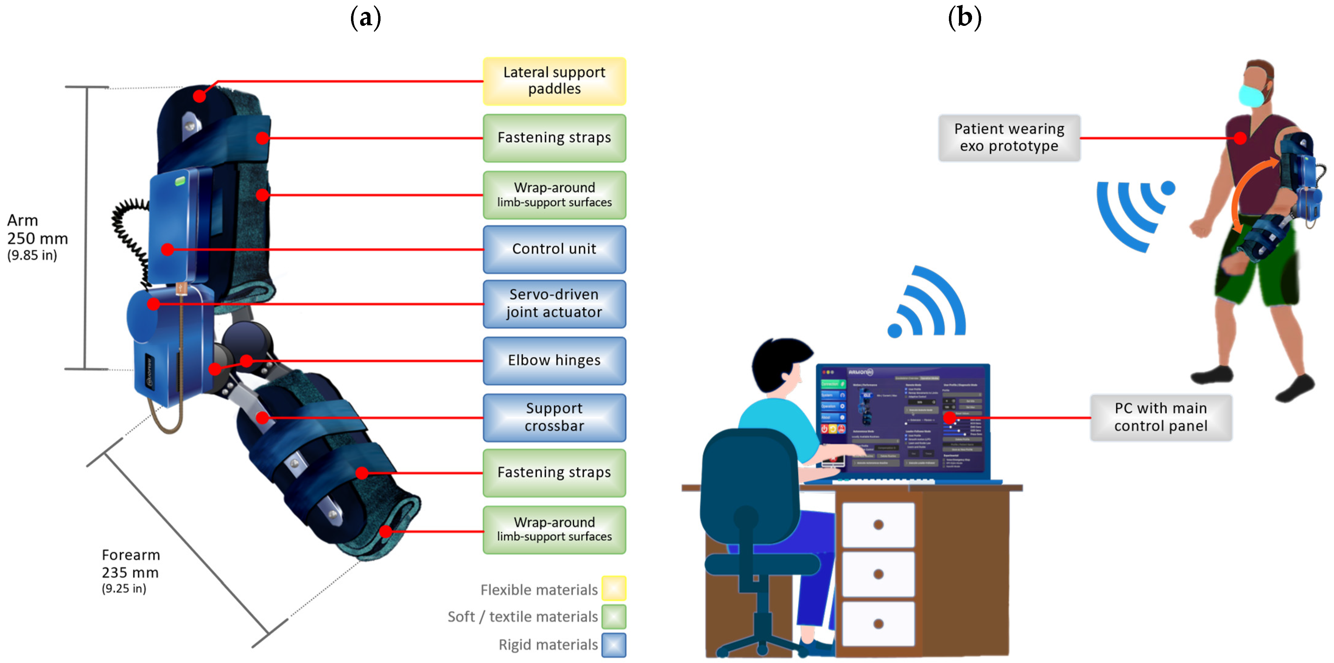
3.1. Robotic Exoskeleton Prototype
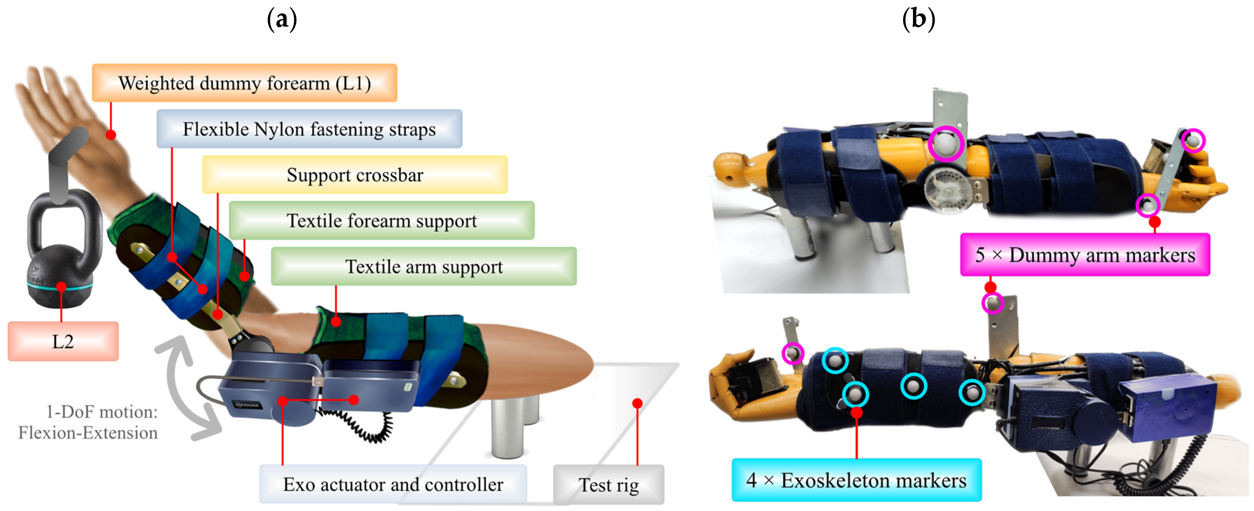
3.2. Experimental Scenario and Operational Environment
3.3. Optical Tracking System (OTS)
4. Methodology and Experimental Design
4.1. Stage 1: Load Design
4.2. Stage 2: Determination of the Effective Transfer of Motion
4.3. Stage 3: Evaluation of Stability and Support in the Upper Limb
4.4. Stage 4: Determination of Response to External Disturbances or Spasticity
5. Results
5.1. Stage 1: Load Design
5.2. Stage 2: Determination of the Effective Transfer of Motion
5.3. Stage 3: Evaluation of Stability and Support in the Upper Limb
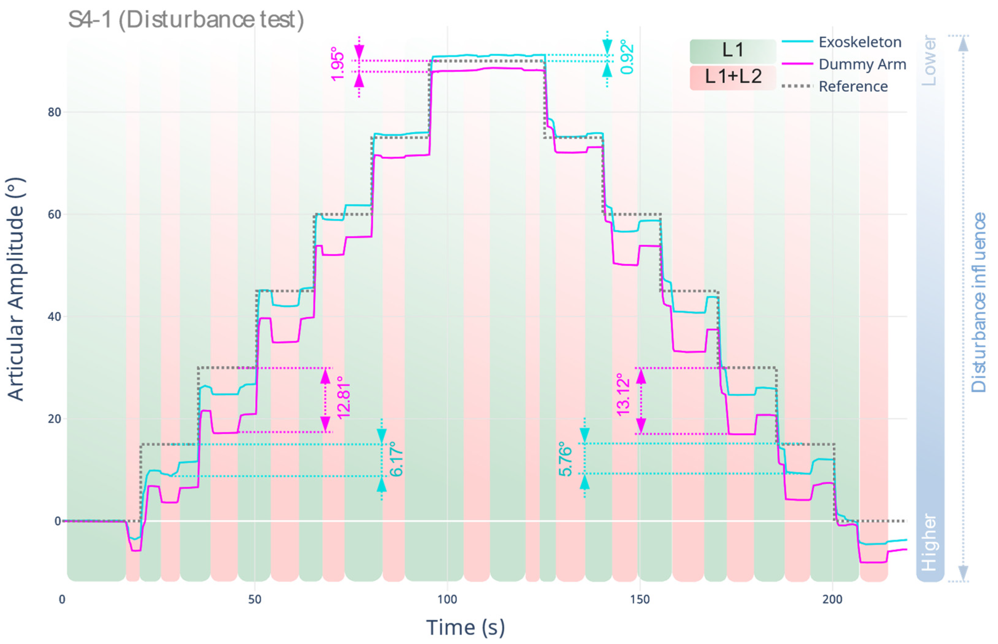
5.4. Stage 4: Determination of Response to External Disturbances or Spasticity
6. Conclusions
Author Contributions
Funding
Institutional Review Board Statement
Informed Consent Statement
Data Availability Statement
Acknowledgments
Conflicts of Interest
References
- Bai, S.; Virk, G.S.; Sugar, T.G. Wearable Exoskeleton Systems: Design, Control and Applications; Bai, S.P., Virk, G.S., Sugar, T., Eds.; Institution of Engineering and Technology: London, UK, 2018. [Google Scholar]
- Gull, M.A.; Bai, S.; Bak, T. A Review on Design of Upper Limb Exoskeletons. Robotics 2020, 9, 16. [Google Scholar] [CrossRef] [Green Version]
- Ruiz-Olaya, A.; Lopez-Delis, A.; Ferreira da Rocha, A. Upper and Lower Extremity Exoskeletons. In Handbook of Biomechatronics; Segil, J., Ed.; Elsevier: London, UK, 2019. [Google Scholar]
- Gopura, R.A.R.C.; Kiguchi, K.; Bandara, D.S.V. A Brief Review on Upper Extremity Robotic Exoskeleton Systems. In Proceedings of the 2011 6th International Conference on Industrial and Information Systems, Kandy, Sri Lanka, 16–19 August 2011; Volume 8502, pp. 346–351. [Google Scholar]
- Qassim, H.M.; Wan Hasan, W.Z. A Review on Upper Limb Rehabilitation Robots. Appl. Sci. 2018, 10, 6976. [Google Scholar] [CrossRef]
- Vélez-Guerrero, M.A.; Callejas-Cuervo, M.; Mazzoleni, S. Artificial Intelligence-based Wearable Robotic Exoskeletons for Upper Limb Rehabilitation: A Review. Sensors 2021, 21, 2146. [Google Scholar] [CrossRef] [PubMed]
- Farzaneh, M.M. A Review Study on the Design of an Exoskeleton Robot. Int. J. Sci. Tech. Res. Eng. 2021, 6, 10–17. [Google Scholar]
- Zhu, M.; Sun, Z.; Chen, T.; Lee, C. Low Cost Exoskeleton Manipulator Using Bidirectional Triboelectric Sensors Enhanced Multiple Degree of Freedom Sensory System. Nat. Commun. 2021, 12, 2692. [Google Scholar] [CrossRef] [PubMed]
- Sanchez-Villamañan, M.D.C.; Gonzalez-Vargas, J.; Torricelli, D.; Moreno, J.C.; Pons, J.L. Compliant Lower Limb Exoskeletons: A Comprehensive Review on Mechanical Design Principles. J. Neuroeng. Rehabil. 2019, 16, 55. [Google Scholar] [CrossRef] [PubMed]
- Stewart, A.M.; Pretty, C.G.; Adams, M.; Chen, X.Q. Review of Upper Limb Hybrid Exoskeletons. IFAC-PapersOnLine 2017, 50, 15169–15178. [Google Scholar] [CrossRef]
- Shahid, T.; Gouwanda, D.; Nurzaman, S.G.; Gopalai, A.A. Moving toward Soft Robotics: A Decade Review of the Design of Hand Exoskeletons. Biomimetics 2018, 3, 17. [Google Scholar] [CrossRef] [Green Version]
- Jain, A.; Jain, K. Soft Exosuit—A Review. Int. Robot. Autom. J. 2020, 6, 99–101. [Google Scholar] [CrossRef]
- Wei, W.; Qu, Z.; Wang, W.; Zhang, P.; Hao, F. Design on the Bowden Cable-Driven Upper Limb Soft Exoskeleton. Appl. Bionics Biomech. 2018, 2018, 1925694. [Google Scholar] [CrossRef] [Green Version]
- Ilami, M.; Bagheri, H.; Ahmed, R.; Skowronek, E.O.; Marvi, H. Materials, Actuators, and Sensors for Soft Bioinspired Robots. Adv. Mater. 2021, 33, 1–47. [Google Scholar] [CrossRef] [PubMed]
- Majidi Fard Vatan, H.; Nefti-Meziani, S.; Davis, S.; Saffari, Z.; El-Hussieny, H. A Review: A Comprehensive Review of Soft and Rigid Wearable Rehabilitation and Assistive Devices with a Focus on the Shoulder Joint. J. Intell. Robot. Syst. 2021, 102, 9. [Google Scholar] [CrossRef]
- He, T.; Lee, C. Evolving Flexible Sensors, Wearable and Implantable Technologies Towards BodyNET for Advanced Healthcare and Reinforced Life Quality. IEEE Open J. Circuits Syst. 2021, 2, 702–720. [Google Scholar] [CrossRef]
- Baniqued, P.D.E.; Baldovino, R.G.; Bugtai, N.T. Design Considerations in Manufacturing Cost-Effective Robotic Exoskeletons for Upper Extremity Rehabilitation. In Proceedings of the 2015 International Conference on Humanoid, Nanotechnology, Information Technology, Communication and Control, Environment and Management (HNICEM), Cebu, Philippines, 9–12 December 2015. [Google Scholar]
- O’Sullivan, L.; Nugent, R.; van der Vorm, J. Standards for the Safety of Exoskeletons Used by Industrial Workers Performing Manual Handling Activities: A Contribution from the Robo-Mate Project to Their Future Development. Procedia Manuf. 2015, 3, 1418–1425. [Google Scholar] [CrossRef] [Green Version]
- Steinhilber, B.; Luger, T.; Schwenkreis, P.; Middeldorf, S.; Bork, H.; Mann, B.; von Glinski, A.; Schildhauer, T.A.; Weiler, S.; Schmauder, M.; et al. The Use of Exoskeletons in the Occupational Context for Primary, Secondary, and Tertiary Prevention of Work-Related Musculoskeletal Complaints. IISE Trans. Occup. Ergon. Hum. Factors 2020, 8, 132–144. [Google Scholar] [CrossRef]
- Lee, S.; Karavas, N.; Quinlivan, B.T.; Louiseryan, D.; Perry, D.; Eckert-Erdheim, A.; Murphy, P.; Greenberg Goldy, T.; Menard, N.; Athanassiu, M.; et al. Autonomous Multi-Joint Soft Exosuit for Assistance with Walking Overground. In Proceedings of the 2018 IEEE International Conference on Robotics and Automation (ICRA), Brisbane, Australia, 21–25 May 2018. [Google Scholar]
- Bessler, J.; Prange-Lasonder, G.B.; Schaake, L.; Saenz, J.F.; Bidard, C.; Fassi, I.; Valori, M.; Lassen, A.B.; Buurke, J.H. Safety Assessment of Rehabilitation Robots: A Review Identifying Safety Skills and Current Knowledge Gaps. Front. Robot. AI 2021, 8, 33. [Google Scholar] [CrossRef]
- Lee, D.J.; Bae, S.J.; Jang, S.H.; Chang, P.H. Design of a Clinically Relevant Upper-Limb Exoskeleton Robot for Stroke Patients with Spasticity. In Proceedings of the 2017 International Conference on Rehabilitation Robotics, ICORR, London, UK, 17–20 July 2017. [Google Scholar]
- Sposito, M.; Di Natali, C.; Toxiri, S.; Caldwell, D.G.; De Momi, E.; Ortiz, J. Exoskeleton Kinematic Design Robustness: An Assessment Method to Account for Human Variability. Wearable Technol. 2020, 1, 1–26. [Google Scholar] [CrossRef]
- Choi, H.; Seo, K.; Hyung, S.; Shim, Y.; Lim, S.C. Compact Hip-Force Sensor for a Gait-Assistance Exoskeleton System. Sensors 2018, 18, 566. [Google Scholar] [CrossRef] [Green Version]
- Sorriento, A.; Porfido, M.B.; Mazzoleni, S.; Calvosa, G.; Tenucci, M.; Ciuti, G.; Dario, P. Optical and Electromagnetic Tracking Systems for Biomedical Applications: A Critical Review on Potentialities and Limitations. IEEE Rev. Biomed. Eng. 2020, 13, 212–232. [Google Scholar] [CrossRef]
- Tiboni, M.; Borboni, A.; Vérité, F.; Bregoli, C.; Amici, C. Sensors and Actuation Technologies in Exoskeletons: A Review. Sensors 2022, 22, 884. [Google Scholar] [CrossRef]
- Martinez-Hernandez, U.; Metcalfe, B.; Assaf, T.; Jabban, L.; Male, J.; Zhang, D. Wearable Assistive Robotics: A Perspective on Current Challenges and Future Trends. Sensors 2021, 21, 6751. [Google Scholar] [CrossRef] [PubMed]
- Khan, M.A.; Saibene, M.; Das, R.; Brunner, I.; Puthusserypady, S. Emergence of Flexible Technology in Developing Advanced Systems for Post-Stroke Rehabilitation: A Comprehensive Review. J. Neural Eng. 2021, 18, 061003. [Google Scholar] [CrossRef] [PubMed]
- Alguacil-Diego, I.M.; Cuesta-Gómez, A.; Contreras-González, A.F.; Pont-Esteban, D.; Cantalejo-Escobar, D.; Sánchez-Urán, M.Á.; Ferre, M. Validation of a Hybrid Exoskeleton for Upper Limb Rehabilitation. A Preliminary Study. Sensors 2021, 21, 7342. [Google Scholar] [CrossRef] [PubMed]
- Veneva, I.; Chakarov, D.; Tsveov, M. Exoskeleton with Soft Actuation and Haptic Interface. In Proceedings of the 2nd International Symposium on Wearable Robotics, WeRob2016, Segovia, Spain, 18–21 October 2016. [Google Scholar]
- Sui, D.; Fan, J.; Jin, H.; Cai, X.; Zhao, J.; Zhu, Y. Design of a Wearable Upper-Limb Exoskeleton for Activities Assistance of Daily Living. In Proceedings of the 2017 IEEE International Conference on Advanced Intelligent Mechatronics (AIM), Munich, Germany, 3–7 July 2017. [Google Scholar]
- Seth, D.; Vardhan Varma, V.K.H.; Anirudh, P.; Kalyan, P. Preliminary Design of Soft Exo-Suit for Arm Rehabilitation. In Digital Human Modeling and Applications in Health, Safety, Ergonomics and Risk Management, Healthcare Applications, Proceedings of the International Conference on Human-Computer Interaction HCII 2019, Orlando, FL, USA, 26–31 July 2019; Lecture Notes in Computer Science; Duffy, V., Ed.; Springer: Cham, Switzerland, 2019. [Google Scholar]
- O’Neill, C.T.; McCann, C.M.; Hohimer, C.J.; Bertoldi, K.; Walsh, C.J. Unfolding Textile-Based Pneumatic Actuators for Wearable Applications. Soft Robot. 2022, 9, 163–172. [Google Scholar] [CrossRef] [PubMed]
- Pérez Vidal, A.F.; Rumbo Morales, J.Y.; Ortiz Torres, G.; Sorcia Vázquez, F.D.J.; Cruz Rojas, A.; Brizuela Mendoza, J.A.; Rodríguez Cerda, J.C. Soft Exoskeletons: Development, Requirements, and Challenges of the Last Decade. Actuators 2021, 10, 166. [Google Scholar] [CrossRef]
- Planas-Lara, A.E.; Ducun-Lecumberri, M.; Tomás-Royo, J.A.; Marín, J.; Marín, J.J. Objective Techniques to Measure the Effect of an Exoskeleton. Biosyst. Biorobot. 2022, 27, 577–581. [Google Scholar]
- Yahya, M.; Shah, J.A.; Kadir, K.A.; Yusof, Z.M.; Khan, S.; Warsi, A. Motion Capture Sensing Techniques Used in Human Upper Limb Motion: A Review. Sens. Rev. 2019, 39, 504–511. [Google Scholar] [CrossRef]
- Colyer, S.L.; Evans, M.; Cosker, D.P.; Salo, A.I.T. A Review of the Evolution of Vision-Based Motion Analysis and the Integration of Advanced Computer Vision Methods Towards Developing a Markerless System. Sports Med. Open 2018, 4, 24. [Google Scholar] [CrossRef] [Green Version]
- Nagymáté, G.; Kiss, R.M. Application of OptiTrack Motion Capture Systems in Human Movement Analysis. A Systematic Literature Review. Recent Innov. Mechatron. 2018, 5, 1–9. [Google Scholar]
- Alarcón-Aldana, A.C.; Callejas-Cuervo, M.; Bo, A.P.L. Upper Limb Physical Rehabilitation Using Serious Videogames and Motion Capture Systems: A Systematic Review. Sensors 2020, 20, 5989. [Google Scholar] [CrossRef]
- Pasinetti, S.; Nuzzi, C.; Covre, N.; Luchetti, A.; Maule, L.; Serpelloni, M.; Lancini, M. Validation of Marker-Less System for the Assessment of Upper Joints Reaction Forces in Exoskeleton Users. Sensors 2020, 20, 3899. [Google Scholar] [CrossRef] [PubMed]
- Pacifico, I.; Molteni, F.; Giovacchini, F.; Vitiello, N.; Crea, S.; Scano, A.; Guanziroli, E.; Moise, M.; Morelli, L.; Chiavenna, A.; et al. An Experimental Evaluation of the Proto-Mate: A Novel Ergonomic Upper-Limb Exoskeleton to Reduce Workers’ Physical Strain. IEEE Robot. Autom. Mag. 2020, 27, 54–65. [Google Scholar] [CrossRef]
- Li, X.; Li, W.; Li, Q. Method, Design, and Evaluation of an Exoskeleton for Lifting a Load in Situ. Appl. Bionics Biomech. 2021, 2021, 5513013. [Google Scholar] [CrossRef] [PubMed]
- Samper-Escudero, J.L.; Contreras-Gonzalez, A.F.; Pont-Esteban, D.; Saez-Saez, F.J.; Sanchez-Uran, M.A.; Ferre, M. Assessment of an Upper Limb Exosuit with Textile Coupling. In Proceedings of the 2020 IEEE International Conference on Human-Machine Systems (ICHMS), Rome, Italy, 7–9 September 2020. [Google Scholar]
- Samper-Escudero, J.L.; Coloma, S.; Olivares-Mendez, M.A.; Sanchez-Uran, M.A.; Ferre, M. Assessment of a Textile Portable Exoskeleton for the Upper Limbs’ Flexion. In Proceedings of the 2nd IEEE International Conference on Human-Machine Systems ICHMS 2021, Magdeburg, Germany, 8–10 September 2021. [Google Scholar]
- Piña-Martínez, E.; Roberts, R.; Leal-Merlo, S.; Rodriguez-Leal, E. Vision System-Based Design and Assessment of a Novel Shoulder Joint Mechanism for an Enhanced Workspace Upper Limb Exoskeleton. Appl. Bionics Biomech. 2018, 2018, 6019381. [Google Scholar] [CrossRef] [PubMed]
- Huysamen, K.; Bosch, T.; de Looze, M.; Stadler, K.S.; Graf, E.; O’Sullivan, L.W. Evaluation of a Passive Exoskeleton for Static Upper Limb Activities. Appl. Ergon. 2018, 70, 148–155. [Google Scholar] [CrossRef]
- Vélez-Guerrero, M.A.; Callejas-Cuervo, M.; Mazzoleni, S. Design, Development, and Testing of an Intelligent Wearable Robotic Exoskeleton Prototype for Upper Limb Rehabilitation. Sensors 2021, 21, 5411. [Google Scholar] [CrossRef]
- Vélez-Guerrero, M.A.; Callejas-Cuervo, M.; Mazzoleni, S. Integration and Testing of a High-Torque Servo-Driven Joint and Its Electronic Controller with Application in a Prototype Upper Limb Exoskeleton. Sensors 2021, 21, 7720. [Google Scholar] [CrossRef]
- OptiTrack OptiTrack—Motion Capture Systems. Available online: https://optitrack.com/ (accessed on 26 April 2022).
- Bi, S.; Gu, Y.; Zou, J.; Wang, L.; Zhai, C.; Gong, M. High Precision Optical Tracking System Based on near Infrared Trinocular Stereo Vision. Sensors 2021, 21, 2528. [Google Scholar] [CrossRef]
- van der Kruk, E.; Reijne, M.M. Accuracy of Human Motion Capture Systems for Sport Applications; State-of-the-Art Review. Eur. J. Sport Sci. 2018, 18, 806–819. [Google Scholar] [CrossRef]
- Dudzik, S. Application of the Motion Capture System to Estimate the Accuracy of a Wheeled Mobile Robot Localization. Energies 2020, 13, 6437. [Google Scholar] [CrossRef]
- Ceseracciu, E.; Sawacha, Z.; Cobelli, C. Comparison of Markerless and Marker-Based Motion Capture Technologies through Simultaneous Data Collection during Gait: Proof of Concept. PLoS ONE 2014, 9, e87640. [Google Scholar] [CrossRef] [PubMed]
- Vélez-Guerrero, M.A.; Callejas-Cuervo, M.; Álvarez, J.C.; Mazzoleni, S.; López, A.M.; Álvarez, D.; Gonzalez, L. Protocol Proposal for the Mechanical Evaluation of a Soft Robotic Exoskeleton Using an Optical Motion Capture System. In Proceedings of the 2022 Global Medical Engineering Physics Exchanges/Pan American Health Care Exchanges (GMEPE/PAHCE), Panamá City, Panamá, 21–26 March 2022. [Google Scholar]
- Plagenhoef, S.; Evans, F.G.; Abdelnour, T. Anatomical Data for Analyzing Human Motion. Res. Q. Exerc. Sport 1983, 54, 169–178. [Google Scholar] [CrossRef]
- De Leva, P. Adjustments to Zatsiorsky-Seluyanov’s Segment Inertia Parameters. J. Biomech. 1996, 29, 1223–1230. [Google Scholar] [CrossRef]
- Walpole, S.C.; Prieto-Merino, D.; Edwards, P.; Cleland, J.; Stevens, G.; Roberts, I. The Weight of Nations: An Estimation of Adult Human Biomass. BMC Public Health 2012, 12, 439. [Google Scholar] [CrossRef] [PubMed] [Green Version]
- Wu, Y.N.; Park, H.S.; Chen, J.J.; Ren, Y.; Roth, E.J.; Zhang, L.Q. Position as Well as Velocity Dependence of Spasticity-Four-Dimensional Characterizations of Catch Angle. Front. Neurol. 2018, 9, 863. [Google Scholar] [CrossRef] [PubMed] [Green Version]
- Schmit, B.D.; Dhaher, Y.; Dewald, J.P.A.; Zev Rymer, W. Reflex Torque Response to Movement of the Spastic Elbow: Theoretical Analyses and Implications for Quantification of Spasticity. Ann. Biomed. Eng. 1999, 27, 815–829. [Google Scholar] [CrossRef] [PubMed]
- McGibbon, C.A.; Sexton, A.; Jones, M.; O’Connell, C. Quantification of Elbow Muscle Tone from an Instrumented Manual Stretch-Reflex Test. Phys. Med. Rehabil. Res. 2016, 1, 1–11. [Google Scholar] [CrossRef] [Green Version]
- Katz, R.T.; Rovai, G.P.; Brait, C.; Rymer, W.Z. Objective Quantification of Spastic Hypertonia. Arch. Med. Rehabil. 1992, 73, 339–347. [Google Scholar] [CrossRef]


| Steps | Detailed Description |
|---|---|
| S1-1 | Determination of the average natural weight of the upper limb of the human body, specifically the forearm section, for adult male and female subjects. |
| S1-2 | Determination of the variation in muscle tone, perceived as a variation in arm weight (load increase), for the same population group described in S1.1. |
| Collected Data | Analysis/Expected Outcome |
| S1-1, S1-2: Anthropometric measurements (weight) [Theoretical data]. |
|
| Steps | Detailed Description |
|---|---|
| S2-1 | Motion type: References established at fixed points with an articular amplitude of 0°, 15°, 30°, 45°, 60°, 75°, and 90°. Cycles: Once in each position, in an ascending and descending direction. Load type: L1. |
| S2-2 | Motion type and cycles: As described in S2-1. Load type: L1 + L2. |
| Collected Data | Analysis/Expected Outcome |
| S2-1, S2-2: Joint amplitude in degrees. S2-2: Deformation, displacement or misalignment using OTS. | The results obtained both in S2-1 (baseline) and S2-2 are contrasted, establishing the amount of error using RMSE, providing a conclusion about the effective motion transfer. |
| Steps | Detailed Description |
|---|---|
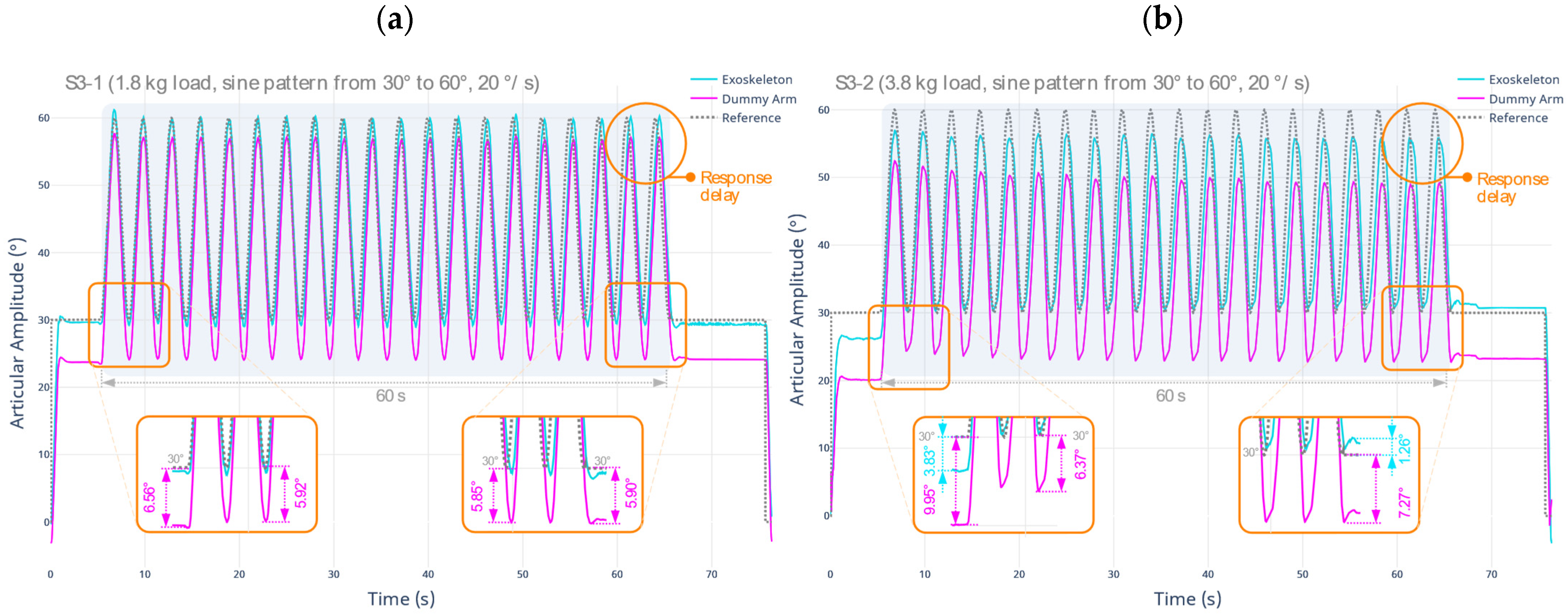
| S3-1 | Motion type: Sinusoidal pattern with joint amplitude between 30° and 60°, angular velocity of 20°/s. Length: 60 s. Load type: L1. |
| S3-2 | Motion type and length: As described in S3-1. Load type: L1 + L2. |
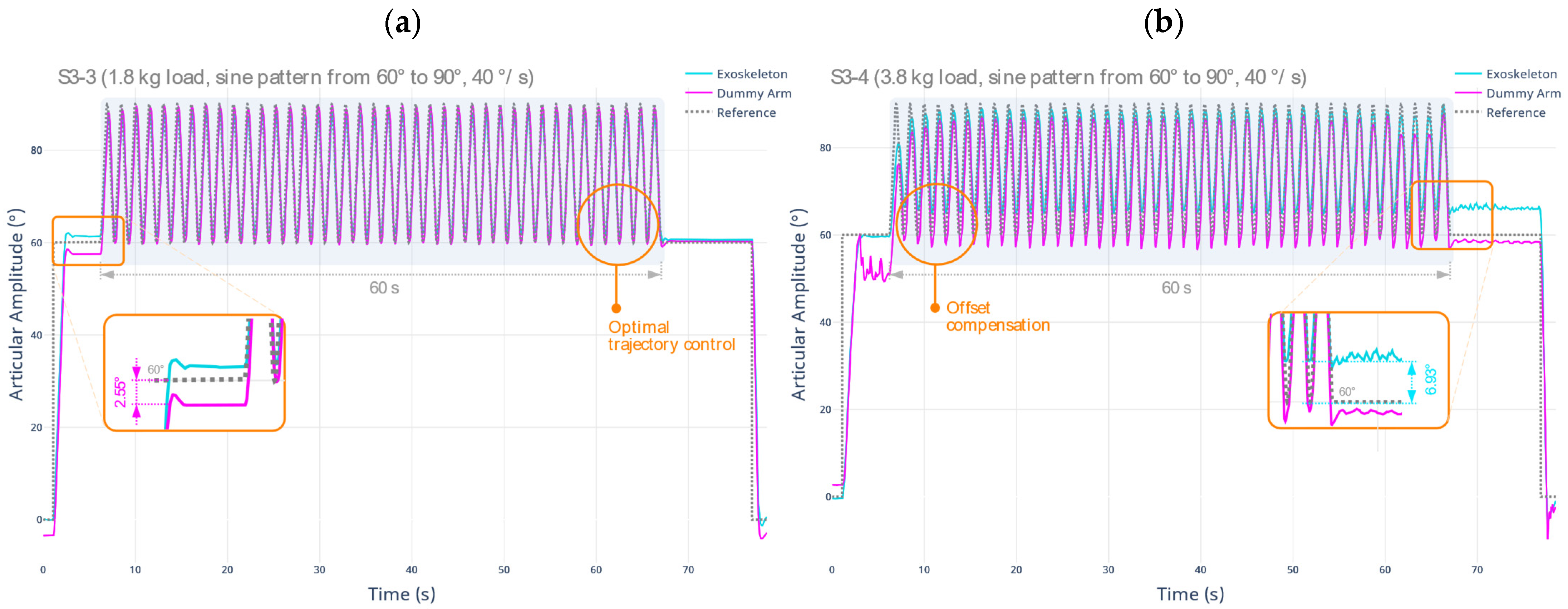
| S3-3 | Motion type: Sinusoidal pattern with joint amplitude between 60° and 90°, angular velocity of 40°/s. Length: 60 s. Load type: L1. |
| S3-4 | Motion type and length: As described in S3-3. Load type: L1 + L2. |
| Collected Data | Analysis/Expected Outcome |
| From S3.1 to S3.4: Joint amplitude in degrees. S3-2, S3-4: Deformation, displacement or misalignment using OTS. | The results obtained both in S3-1 and S3-3 (baseline) and in the motions with load performed in S3-2 and S3-4 are contrasted, respectively, establishing the amount of error using RMSE, concluding about the stability and support in the upper limb. |
| Steps | Detailed Description |
|---|---|
| S4-1 | Motion type: References established at fixed points with an articular amplitude of 0°, 15°, 30°, 45°, 60°, 75°, and 90°. Cycles: Once in each position, in an ascending and descending direction. Load type: L1, then L1 + L2 when the reference is reached. |
| S4-2 | Motion type: Sinusoidal pattern with ascending joint amplitude between 45° and 90° with oscillations of 20°, angular velocity of 20°/s. Cycles: Once. Load type: L1. |
| S4-3 | Motion type and cycles: As described in S4-3. Load type: L1 + L2. |
| S4-4 | Motion type: Sinusoidal pattern with ascending joint amplitude between 0° and 45° with oscillations of 20°, angular velocity of 40°/s. Cycles: Once. Load type: L1. |
| S4-5 | Motion type and cycles: As described in S4-4. Load type: L1 + L2. |
| Collected Data | Analysis/Expected Outcome |
| From S4-1 to S4-5: Joint amplitude in degrees. S4-1, S4-3, S4-5: Deformation, displacement or misalignment using OTS. |
|
| Segment | Male [55] | Male [56] | Female [55] | Female [56] | Avg. | Avg. Weight |
|---|---|---|---|---|---|---|
| Forearm | 1.87% | 1.62% | 1.57% | 1.38% | 1.61% | 1.3 kg |
| Hand | 0.65% | 0.61% | 0.50% | 0.56% | 0.58% | 0.5 kg |
| Forearm and Hand | 2.52% | 2.23% | 2.07% | 1.94% | 2.19% | 1.8 kg |
| Rigid Body | S2-1 | S2-2 | ||
|---|---|---|---|---|
| Max. Error | RMSE | Max. Error | RMSE | |
| Exoskeleton | 2.47° | 1.52° | 11.05° | 4.78° |
| Dummy Arm | 3.48° | 2.90° | 10.61° | 6.71° |
| Rigid Body | S3-1 | S3-2 | ||||
|---|---|---|---|---|---|---|
| Max. Pos. Error | Positioning RMSE | Max. Displacement | Max. Pos. Error | Positioning RMSE | Max. Displacement | |
| Exoskeleton | 1.13° | 2.64° | N/A | 3.83° | 2.89° | N/A |
| Dummy Arm | 6.56° | 7.48° | 17.67 mm | 9.95° | 10.39° | 28.81 mm |
| Rigid Body | S3-3 | S3-4 | ||||
|---|---|---|---|---|---|---|
| Max. Pos. Error | Positioning RMSE | Max. Displacement | Max. Pos. Error | Positioning RMSE | Max. Displacement | |
| Exoskeleton | 1.72° | 0.79° | N/A | 6.93° | 7.96° | N/A |
| Dummy Arm | 2.55° | 1.83° | 6.86 mm | 10.31° | 8.19° | 20.98 mm |
| Rigid Body | S4-2 | S4-3 | ||||
|---|---|---|---|---|---|---|
| Max. Pos. Error | Positioning RMSE | Max. Displacement | Max. Pos. Error | Positioning RMSE | Max. Displacement | |
| Exoskeleton | 1.02° | 0.81° | N/A | 4.79° | 2.78° | N/A |
| Dummy Arm | 3.73° | 2.35° | 7.7 mm | 7.78° | 4.45° | 9.23 mm |
| Rigid Body | S4-4 | S4-5 | ||||
|---|---|---|---|---|---|---|
| Max. Pos. Error | Positioning RMSE | Max. Displacement | Max. Pos. Error | Positioning RMSE | Max. Displacement | |
| Exoskeleton | 6.66° | 3.67° | N/A | 10.82° | 5.57° | N/A |
| Dummy Arm | 6.66° | 3.90° | 2.99 mm | 15.99° | 7.18° | 19.95 mm |
Publisher’s Note: MDPI stays neutral with regard to jurisdictional claims in published maps and institutional affiliations. |
© 2022 by the authors. Licensee MDPI, Basel, Switzerland. This article is an open access article distributed under the terms and conditions of the Creative Commons Attribution (CC BY) license (https://creativecommons.org/licenses/by/4.0/).
Share and Cite
Vélez-Guerrero, M.A.; Callejas-Cuervo, M.; Álvarez, J.C.; Mazzoleni, S. Assessment of the Mechanical Support Characteristics of a Light and Wearable Robotic Exoskeleton Prototype Applied to Upper Limb Rehabilitation. Sensors 2022, 22, 3999. https://doi.org/10.3390/s22113999
Vélez-Guerrero MA, Callejas-Cuervo M, Álvarez JC, Mazzoleni S. Assessment of the Mechanical Support Characteristics of a Light and Wearable Robotic Exoskeleton Prototype Applied to Upper Limb Rehabilitation. Sensors. 2022; 22(11):3999. https://doi.org/10.3390/s22113999
Chicago/Turabian StyleVélez-Guerrero, Manuel Andrés, Mauro Callejas-Cuervo, Juan C. Álvarez, and Stefano Mazzoleni. 2022. "Assessment of the Mechanical Support Characteristics of a Light and Wearable Robotic Exoskeleton Prototype Applied to Upper Limb Rehabilitation" Sensors 22, no. 11: 3999. https://doi.org/10.3390/s22113999
APA StyleVélez-Guerrero, M. A., Callejas-Cuervo, M., Álvarez, J. C., & Mazzoleni, S. (2022). Assessment of the Mechanical Support Characteristics of a Light and Wearable Robotic Exoskeleton Prototype Applied to Upper Limb Rehabilitation. Sensors, 22(11), 3999. https://doi.org/10.3390/s22113999