1. Introduction
Over the past two decades, vehicle comfort and road holding have become important considerations for car manufacturers owing to their ability to mitigate the effects caused by road imperfections. Semi-active suspensions have received considerable attention in this context. Semi-active devices use smart materials, such as magnetorheological (MR) fluids, which can shift from Newtonian to Bingham behavior within a microsecond under the influence of an external magnetic field. MR fluids offer a high yield strength and a wide range of operating temperatures [
1,
2]. MR dampers with MR fluids have advantages such as rapid response, low-voltage required to control the damping force, and structural simplicity [
3,
4,
5]. Different structures of MR dampers have been studied and applied in control systems. For instance, Solomon et al. [
6] designed a mono-tube MR damper by focusing on the performance of indices such as damping force, dynamic range, and valve ratio. They concluded that the design of an MR damper is highly dependent on the performance indices. The mono-tube-type MR damper is more commonly used than other models. However, it requires a larger volume to generate a high damping force, which is inconvenient for many applications [
7,
8]. Studies have attempted to enhance the damping force using the twin-tube model with low volume; however, this has proved difficulties owing to its complexity, hydraulic imbalance, and limited dynamic range [
3,
9]. Generating a highly controllable damping force with a compact model remains challenging. Jiang et al. [
10] presented a novel design of a multichannel bypass MR damper operating under three working modes. Compared with conventional MR models, their model offers a larger adjustment range and improves the vibration response. However, this model is complex, requires a larger volume, and exhibits a high friction force, which can decay its damping force. By contrast, hybrid models generate a high damping force and address the problem of failure safety for field-off [
11,
12,
13]. To achieve model simplicity and compactness while improving its damping characteristics, Bai et al. [
14] proposed an annular-radial-duct MR damper to improve the efficiency of the MR damper. Their experimental results were compared with those obtained using an MR damper manufactured by LORD Corp. (Cary, NC, USA) (commercially available on the market), and the proposed model provided both a larger damping force and damping range compared with the commercial damper. Several studies have reported that the annular-radial model improves the controllable damping force and has a wide adjustable range [
15,
16,
17]. However, research on the application of MR dampers based on the annular-radial model to conventional engine-powered or electric vehicles remains limited.
The main technical contribution of this study is the introduction of a novel type of MR damper to improve ride comfort designed based on the annular-radial model and its application to electric vehicles (EVs) powered by in-wheel motors (IWMs). Currently, several manufacturers are attempting to adopt this promising future technology in EVs. The vehicles powered by IWMs offer many benefits compared with internal combustion engine vehicles, such as high torque and vehicle efficiency up to 98% [
18]. However, this technology has some serious limitations that can affect its reliability, such as increased sprung mass, which can deteriorate the dynamic performance of the vehicle, braking problems, and deterioration of motor bearing [
19,
20,
21]. To address the challenges faced by annular-radial models that lack failure safety, we proposed a hybrid annular radial-type MR damper that achieves failure safety using a permanent magnet in addition to the annular and radial ducts that are connected in series. The model was designed and mathematically formulated to represent the governing motion. The performance of the new model was then analytically validated, and the results were compared with those reported in [
14] to demonstrate the advantages of the proposed hybrid annular radial magnetorheological damper (HARMRD).
3. Modeling of Hybrid Annular Radial MR Damper
The proposed model operates based on the principles of valve mode [
8,
23,
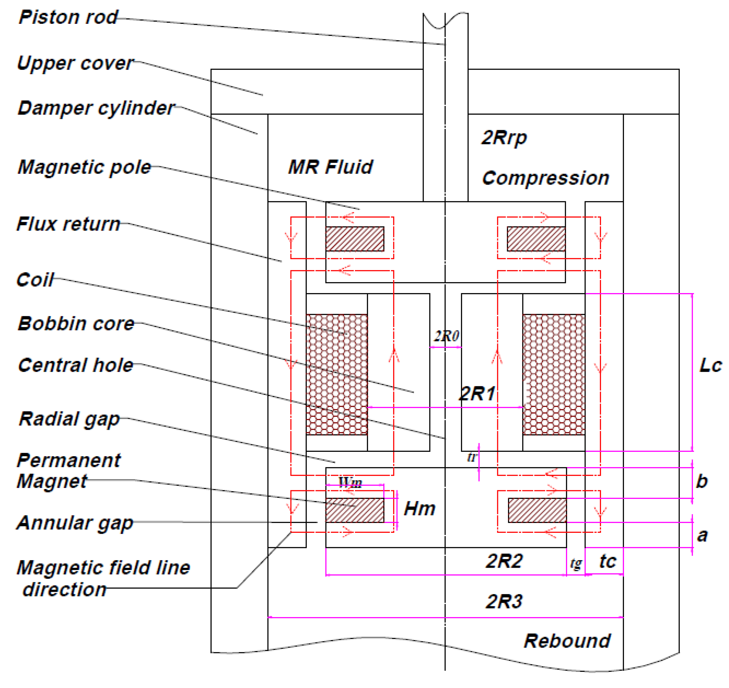
24]. As shown in
Figure 1, the model comprises two annular gaps, two radial gaps, and one central hole to facilitate the flow of the MR fluid from the low-pressure to the high-pressure side, and vice versa. The total pressure drop inside the valve is expressed as follows:
where
,
are the pressure drops in the annular gap, radial gap, and central hole, respectively. The pressure in the annular flow gap is expressed as [
17]
where
and
are the viscous pressure drop and field-dependent pressure drop, respectively, and are expressed as
The expressions for
,
, and
are deduced from
Figure 1.
where
is the viscosity of the MR fluid;
is the volumetric flow rate of the MR fluid through the annular gap;
is the piston velocity;
is the effective area of the piston valve;
is the length of the annular gap;
is the effective length of the annular gap;
and
are the effective pole lengths below and above the magnet, respectively; and
is the height of the magnet. The pressure drop in the radial gap is determined as
where
and
are the pressure drops due to the MR fluid flowing in the radial gap and the yield stress, respectively.
The pressure drop,
, in the central hole is defined as
where
denotes the length of the central hole. By substituting Equations (3), (4), (9), (10) and (11) into Equation (1), the pressure drop becomes
The viscous damper coefficient can be calculated from Equation (12) as follow
The total damping force can be calculated using Equation (12) as
To evaluate the performance of the HARMRD, the dynamic range (
K) was calculated as the ratio of the field-dependent force to the viscous damping force.
4. Finite Element Analysis of HARMRD
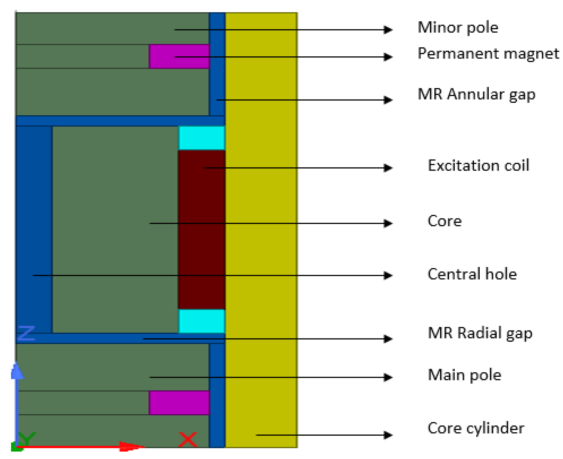
Mathematically, calculating the damping force and dynamic range of the HARMRD is challenging owing to the nonlinearity of the materials that make up the model. For convenience, finite element analysis (FEA) was performed using the ANSYS/Maxwell software.
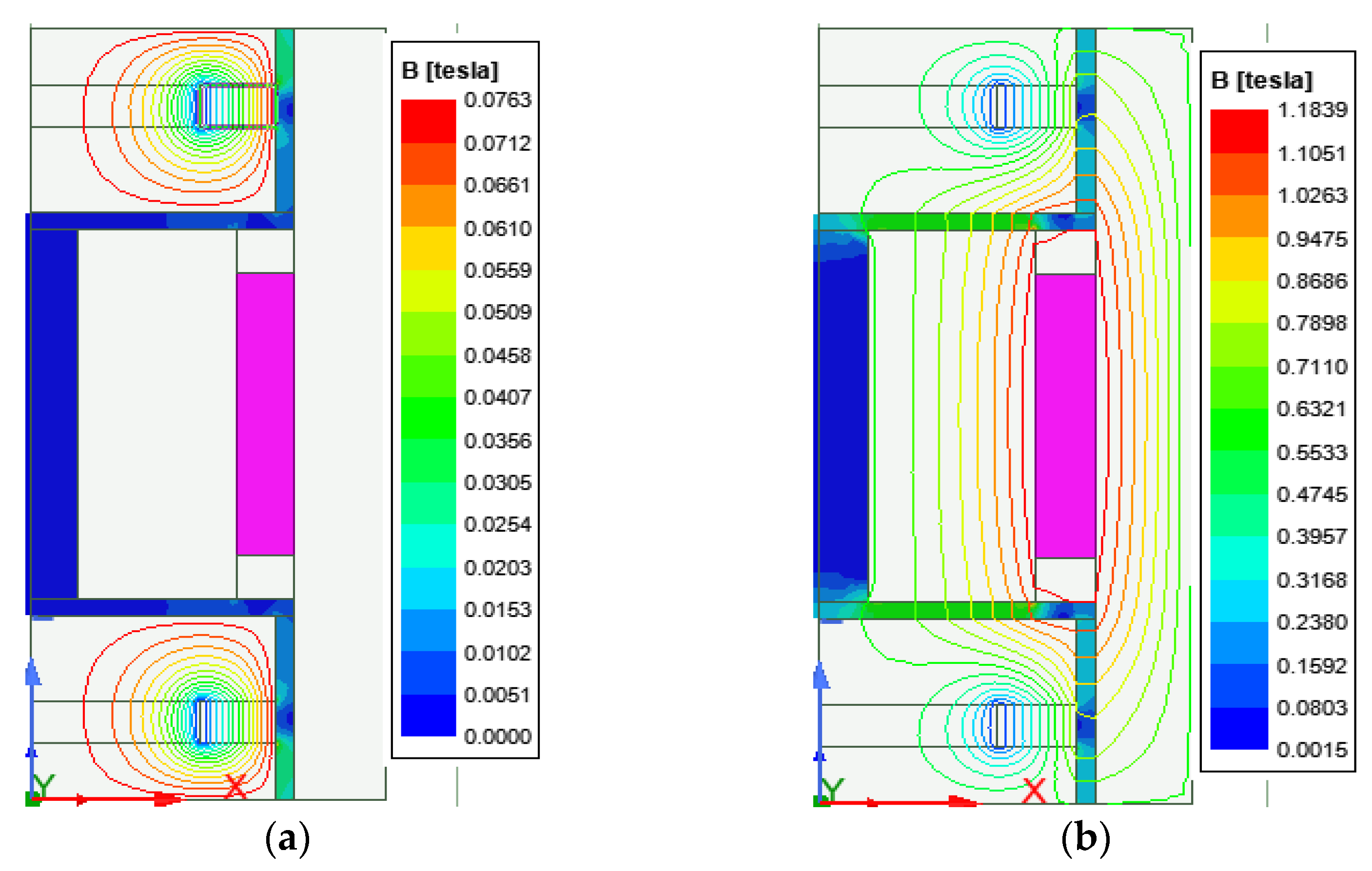
Figure 2 shows the axisymmetric model of the HARMR valve used in the simulation. The results of the two cases considered in the simulation are presented in
Figure 3a,b. The distribution of the magnetic flux lines and magnetic flux density for the HARMR valve in the absence of excitation current to the coil is shown in
Figure 3a. Evidently, the magnetic flux lines and density are concentrated around the PMs, and in this case, the proposed model continuously experiences a magnetic field around the annular channel. In addition, the magnetic fields generated in the annular gap and radial gap are 0.06 T and 0.01 T, respectively.
Figure 3b shows the generated magnetic field lines and flux density when both the magnets and the electrical coil are operating. In this case, the initial magnetic field from the magnets is strengthened by the field generated by the coil after excitation. A current variation of 0–1.5 A with an interval of 0.25 A is supplied to the coil.
Unlike the magnetic field from the magnets, that from the coil, passes through both radial and annular directions and extends to the core cylinder to form a complete cycle, as shown in
Figure 3a. After supplying a current of 1.5 A to the coil, the magnetic field densities generated for both radial and annular gaps were 0.56 T and 0.44 T, respectively. A typical magnetic field problem is described by defining its geometry, material properties, magnetic input, and boundary conditions. Based on the properties of MR fluid (MRF-132DG) [
25] and FEM analysis results for electromagnetic characteristics shown in
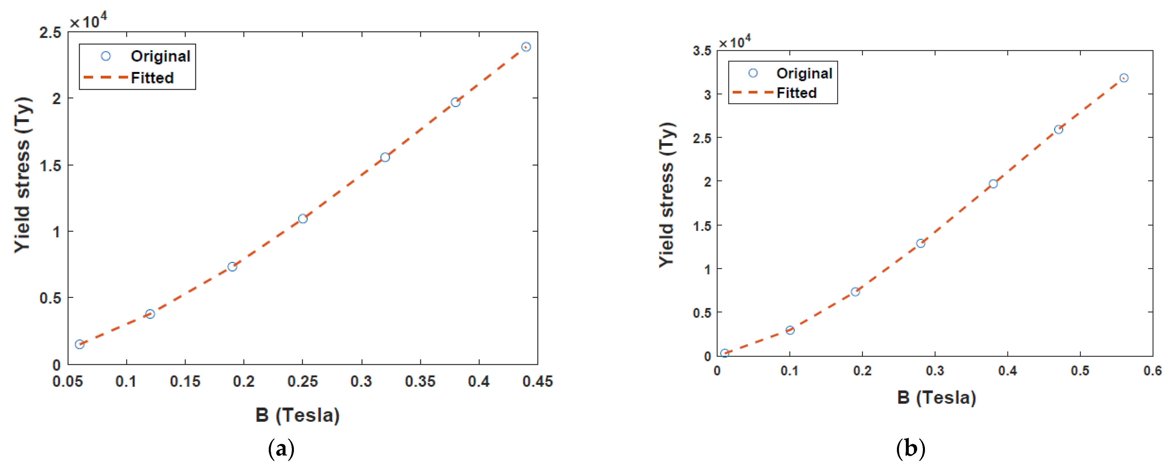
Figure 3, relationship between yield stress and magnetic field intensity can be obtained as presented in
Figure 4.
Figure 4a,b depict the relationship between magnetic flux density
and yield stress
in the annular and radial channels, respectively. The data points in
Figure 4 were fitted into a polynomial curve using the least square method in MATLAB simulation software. Evidently, the radial channel generates a higher yield stress and magnetic field than the annular duct. The yield stresses in the two channels were deduced from
Figure 4a,b as follows.
where
and
are the yield stresses in the annular and radial channels, respectively. To evaluate the performance of the proposed model, the damping force was calculated based on the equations in
Section 3.
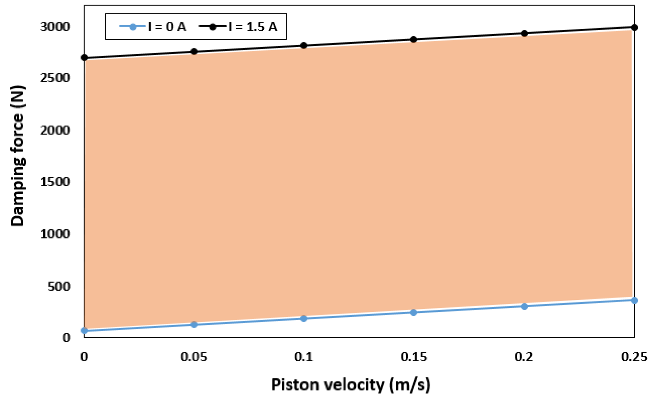
Figure 5 shows the minimum damping force when no current is supplied to the coil (field-off condition) and the maximum damping force generated when the coil is excited (field-on condition). When the field is off (I = 0 A), a damping force of 70.507–365.98 N is generated for piston velocities of 0 and 0.25 m/s, respectively. By contrast, when the field is on (I = 1.5 A), the damping force increases from 2696.3 N to 2991.8 N for the same piston velocities. In addition, the highest dynamic range of 3.19 and 47.63 was obtained at a piston velocity of 0.05 m/s for field-off and field-on states, respectively. However, as the piston velocity increases, the dynamic range decreases significantly. For a constant speed of 0.25 m/s, dynamic ranges of 2.24 and 11.13 were obtained for the field-off and field-on states, respectively.
5. Optimization of the HARMR Valve
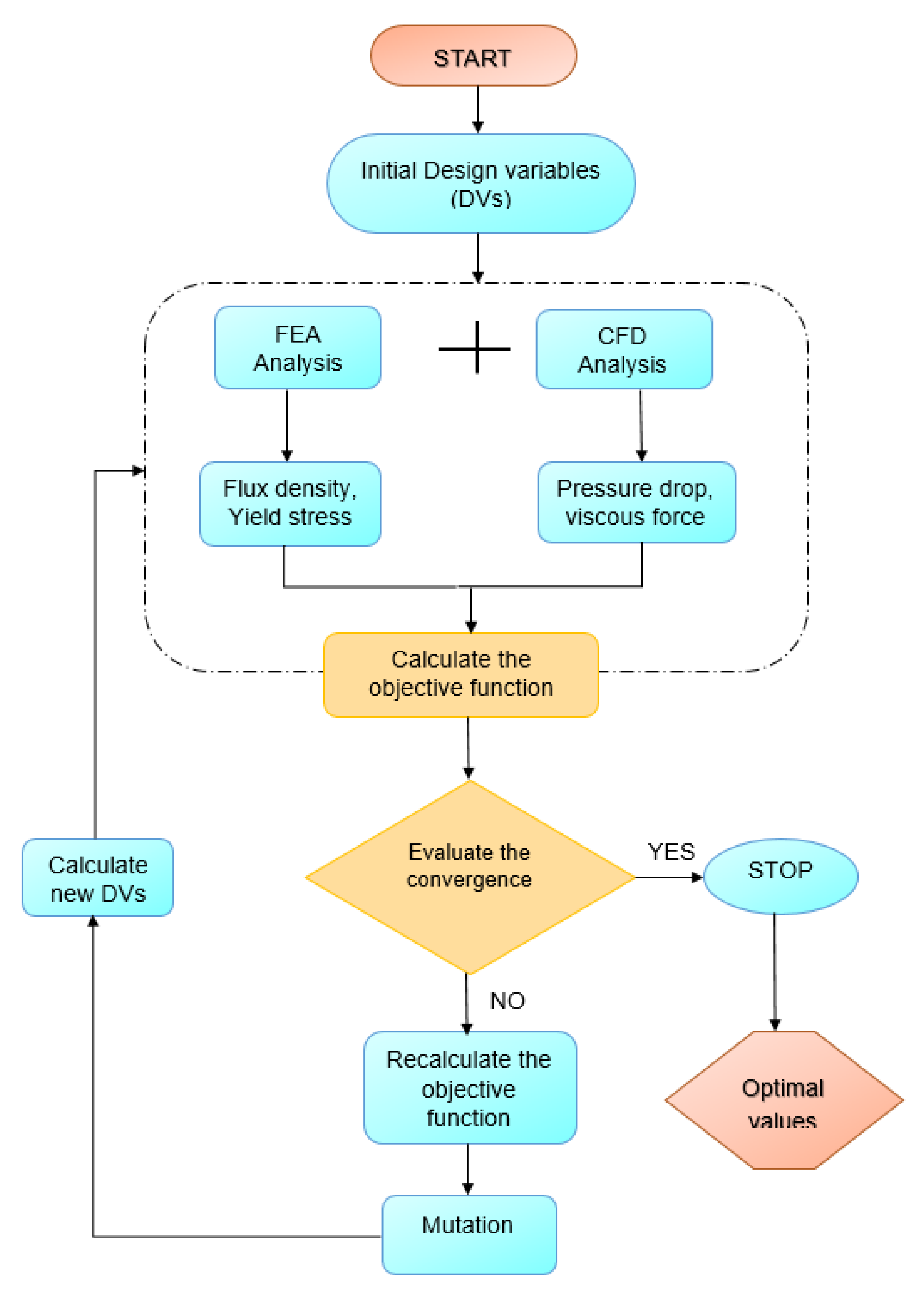
After obtaining the performance indices from the initial design parameters, a multi-objective genetic algorithm (MGA) is used to optimize the HARMRD. MGA is based on concepts from natural selection and genetics. It is commonly used to obtain high-quality solutions to search and optimization problems. The optimization process used in this study is depicted in
Figure 6. During optimization, seven design variables (DVs) were selected based on their effects on the performance indices, including the damping force and dynamic range. The selected DVs are the piston radius
, radius of circular disc
, radius of the core from the central hole
, coil width
, piston radius
, annular duct
, and main pole
. The upper and lower bounds of the design variables are listed in
Table 2. In this study, the damping force and dynamic range were selected as the fitness functions. Ride comfort and suspension travel are two important factors in vehicle suspension design. To maintain the suspension travel short, a larger damping force is required, whereas to achieve better ride comfort, a low damping force and larger dynamic range are required. The fitness function is expressed as follows [
26]:
where
,
are the reference damping force and reference dynamic range, respectively, and
and
are the weighting factors. In addition, the summation of both weighting factors should be equal to 1. To balance both damping force and dynamic range, the weighting factors were chosen as 0.5 in this work.
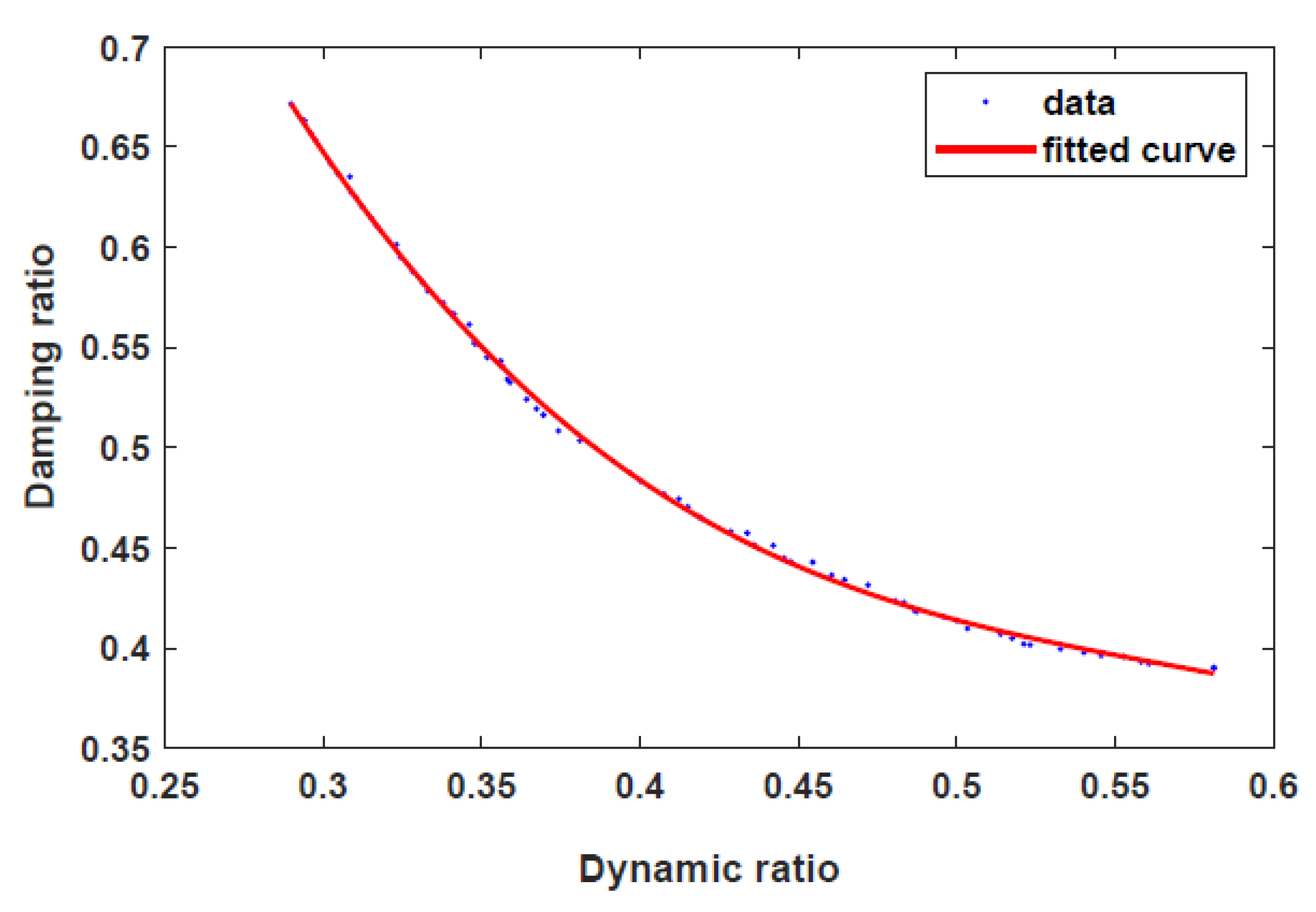
Figure 7 shows the Pareto front generated between the fitness functions. Evidently, the dynamic range decreases with increasing damping force. The optimal design parameters are listed in
Table 3.
Figure 8 shows the dynamic ranges of the optimal HARMRD under various velocity excitations. As it is apparent from this figure, the dynamic range decreases as the piston velocity increases. The wide range of controllability is confirmed by the highest dynamic range experienced at the excitation current of I = 1.5 A. Moreover, the dynamic range obtained during the off-field state indicates that the proposed model addresses the fail-safe problem. The relationship between the dynamic range and piston velocity for the optimal model was determined using MATLAB/Simulink under current excitations ranging from 0 to 1.5 A. During the simulation, a sinusoidal displacement with an amplitude (A) of 0.075 m and frequency of 2 Hz was used.
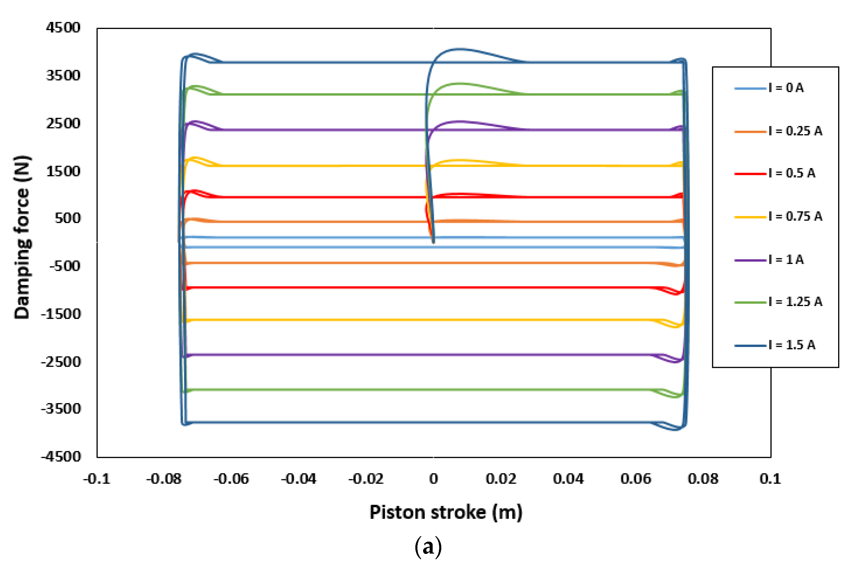
The force-piston stroke and force-piston velocity are shown in
Figure 9a,b, respectively.
Figure 9a depicts the relationship between the damping force and piston stroke (FD-S) for various current excitations. Evidently, FD-S curves gradually rise with the current supplied. Moreover, the damping forces for the compression and extension strokes are symmetric. The small deformation around the top-left corner and bottom-right corner is due to insufficient gas pressure in the accumulator. As shown in
Figure 9a, a minimum damping force of 445.7 N was generated in the off-field state (I = 0 A). By contrast, a maximum damping force of 3753.9 N was obtained when the maximum current (I = 1.5 A) was applied. This indicates that the optimal HARMR model is capable of generating a wide range of damping force (445.7–3753.9 N), which is necessary for achieving better driving comfort.
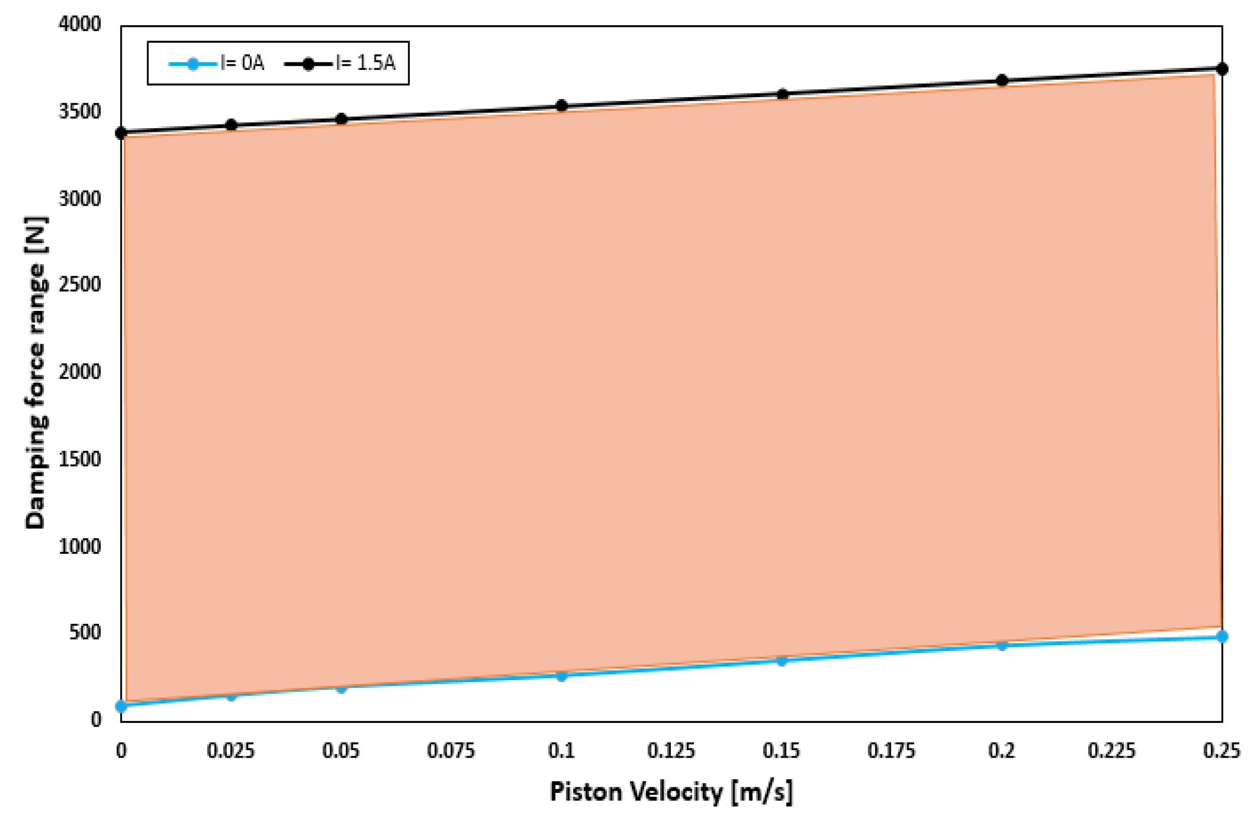
Figure 9b shows the variation of damping force with piston velocity under various current inputs. It is evident that the proposed HARMR model can mimic the behavior of an MR damper. Generally, it is difficult to replicate the MR property in an off-field state. In addition, the damping force increased as the excitation and piston velocities increased. The proposed model generates a damping force range of 445.7–3753.9 N under the piston velocity of 0.25 m/s.
Figure 10 illustrates the damping force range under various velocity inputs. The wide damping force range enables the use of short stroke which is essential for improving the ride comfort and vehicle handling. When the field is off (I = 0 A), a damping force of 87.25–445.7 N is generated for piston velocities of 0 and 0.25 m/s, respectively. By contrast, when the field is on (I = 1.5 A), the damping force increases from 3386.4 N to 3753.9 N for the same piston velocities. Compared with the results in
Figure 5, it can be clearly seen that the damping force range increased after optimization. After optimization, the damping force is 3753.9 N, which is 20% higher than that of 2991.8 N before optimization, and the suspension travel can be restricted with sufficient damping force. The dynamic range under the condition of piston velocity of 0.05 m/s is evaluated by 3.19 and 47.63 at field-off and field-on, respectively, before optimization. However, it increased to values of 3.19 and 48.08 under the same conditions after optimization. These results mean that the damping force can be greatly improved without reducing the dynamic range through optimization. A typical passive damper has a damping force of about 130 to 400 N at a piston velocity of 0.025 to 0.2 m/s [
27]. In the case of the model proposed in this paper, it was confirmed to have a damping force of 147 to 437 N for the same piston speed in the field-off state. From these results, it is confirmed that the proposed model has adequate performance for fail-safe issues. When the damping force per unit volume is calculated based on the maximum damping force, it has values of 0.0535 N/mm
3, 0.0388 N/mm
3, and 0.0597 N/mm
3 for Bai’s model, RD-1005-3 model of LORD Corp. (Cary, NC, USA), and the model proposed in this paper, respectively. The maximum damping force under the same current input of 1.5 A and the piston speed of 0.19 m/s is considered. The volume is calculated using the piston radius, piston rod radius and stroke. From this, it is confirmed that improved damping force can be obtained by using the proposed model compared with both model in previous research work and commercial model.
6. Performance Evaluation of the HARMRD
EVs are typically powered by either a centralized motor or an IWM, depending on the vehicle design. Motors arrangement is the primary difference between these two EV designs. In the IWM design, a motor is installed on each wheel to directly supply torque to the wheels. By contrast, in a conventional layout, the motor is centralized, and the torque is transferred to the wheels via the drive shaft. The IWM configuration offers advantages over conventional models, such as improved efficiency, easy generation of forward and reverse torques, and improved performance of systems such as the anti-lock brake system and traction control system [
28]. However, driving comfort and handling stability are primary considerations in the design of the suspension system. In previous studies, the IWMs integrated into the wheels increased the unsprung mass, which resulted in the deterioration of the tire dynamic road and body vibration acceleration. Several methods have been proposed to tackle the weight issue, including the in-wheel switched reluctant motor (IWSRM) and permanent magnetic synchronous motor (PMSM) [
29]. However, both the IWSRM and PMSM models have been found to experience radial force imbalance due to rotor eccentricity, which affects the ride comfort. However, an IWSRM is affordable and simple. In this study, an SRM coupled inside a wheel was modeled, and a dynamic vibration absorbing structure was connected to the unsprung mass to suppress the vibration of the unsprung mass.
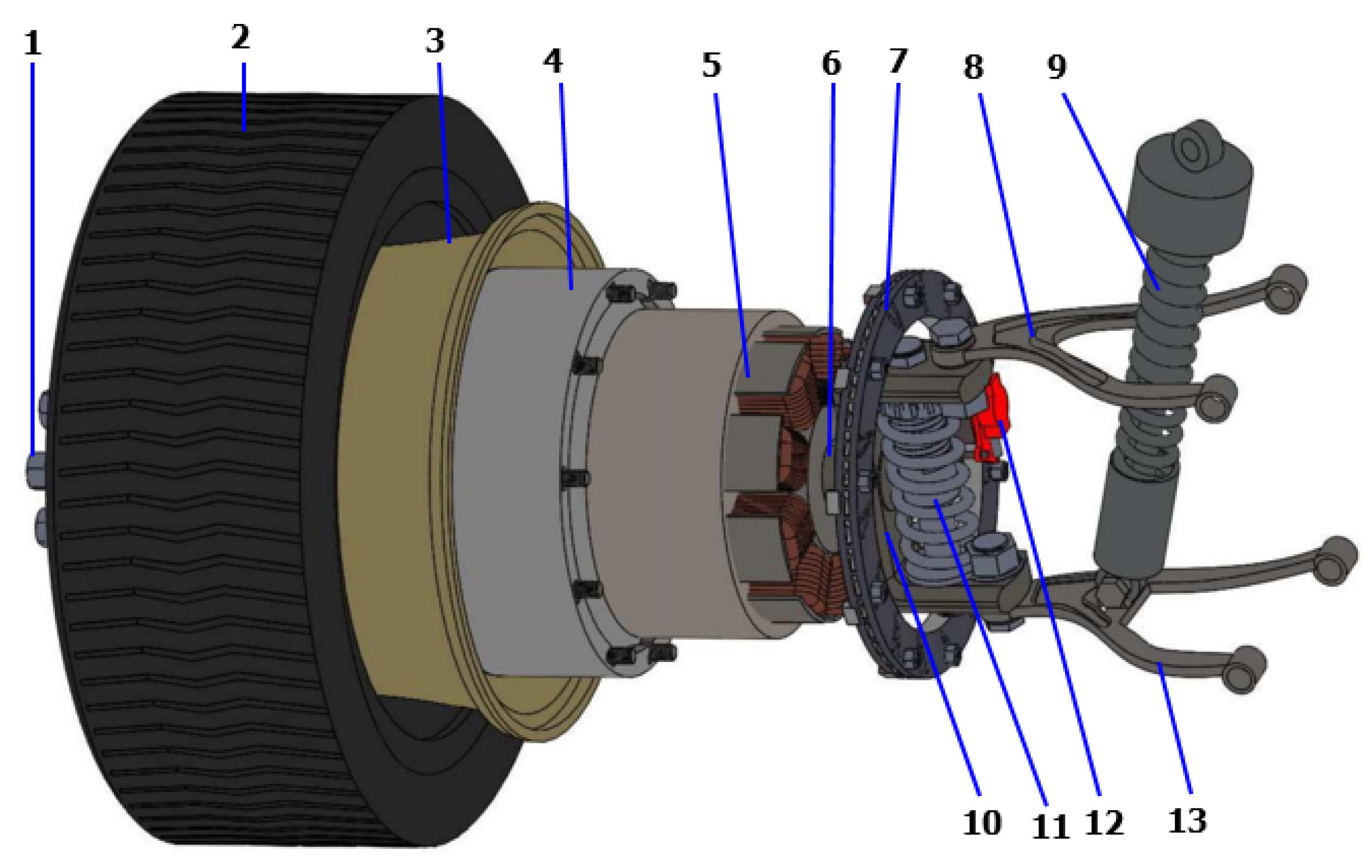
Figure 11 shows the proposed EV suspension powered by the IWM. The proposed IWM comprises 13 components, which are grouped into three parts (wheel and tire, SRM, and suspension dampers). To suppress motor vibration, a small passive damper was installed inside the stator cover, which was connected to the hub shaft. In addition to the small damper in the DVA structure, HARMRD was installed between the lower and upper arms of the suspension to control road-induced vibration.
A co-simulation software (CarSim, V 9.0, Mechanical Simululation Corporation, Ann Arbor, MI, USA) was used to evaluate the effectiveness of the proposed HARMR model for an EV powered by an IWM. The CarSim interface is divided into three main parts: vehicle parameters and drive cycle, MATLAB/Simulink interface, and simulated results. CarSim is widely used to simulate the vehicle performance in terms of ride comfort, handling stability, and power. A D-class sedan with independent suspensions was used in the simulation.
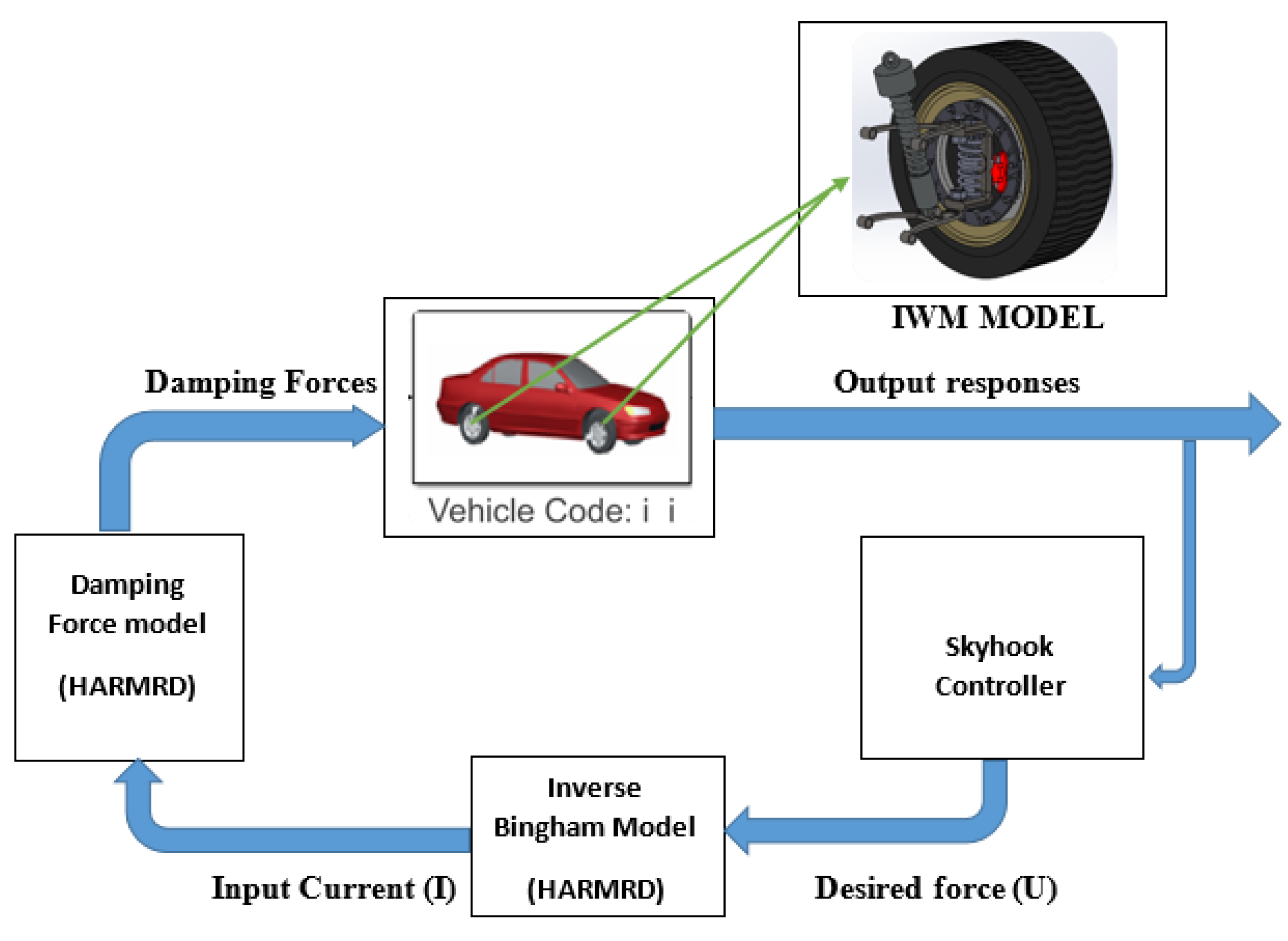
Figure 12 illustrates the simulation in MATLAB/Simulink in conjunction with CarSim. The damping forces (
FD) supplied on each tire were considered as an external input to CarSim, and they were controlled by the Skyhook controller. In CarSim, the full vehicle parameters are specified based on a real vehicle. The considered parameters include the sprung mass, unsprung mass, wheelbase, vehicle width, and vehicle height. The parameters for the full vehicle are listed in
Table 4. Five outputs were obtained from the sensor, namely force rate, body velocity, body deflection, tire deformation, and vertical acceleration. During the simulation, bump and random input roads were adopted from the CarSim software. The moving vehicle velocity for the bump and random road was fixed to 60 km/h. Here, a normal vehicle powered by an engine and an EV powered by an IWM were compared under the same road conditions. For simplicity, only the front-left suspension responses were considered for the full vehicle. For the riding test, a bump road input with amplitudes of 35 mm and 400 mm was used. A vehicle velocity of 60 km/h was used.
The vertical acceleration, suspension deflection, and tire deflection responses of a normal vehicle are shown in
Figure 13. Two cases were investigated and compared during the simulation. First, the vehicle in CarSim was simulated without an external force, that is, passive suspension. Second, the external force from the HARMRD, controlled by the skyhook controller, was supplied to the vehicle. It is evident that the vehicle controlled by the proposed damper suppressed undesirable vibrations compared with the passive suspension. In addition, the proposed model exhibited a fast settling time after the vehicle hit the bump, which confirms the improvement in ride comfort achieved by the proposed model. To statistically verify the performance, the root mean square (RMS) for both the passive and controlled responses was calculated. The RMS values for passive responses decreased by 66.9%, 69.18%, and 18.12% for vertical acceleration, body deflection, and tire deflection, respectively.
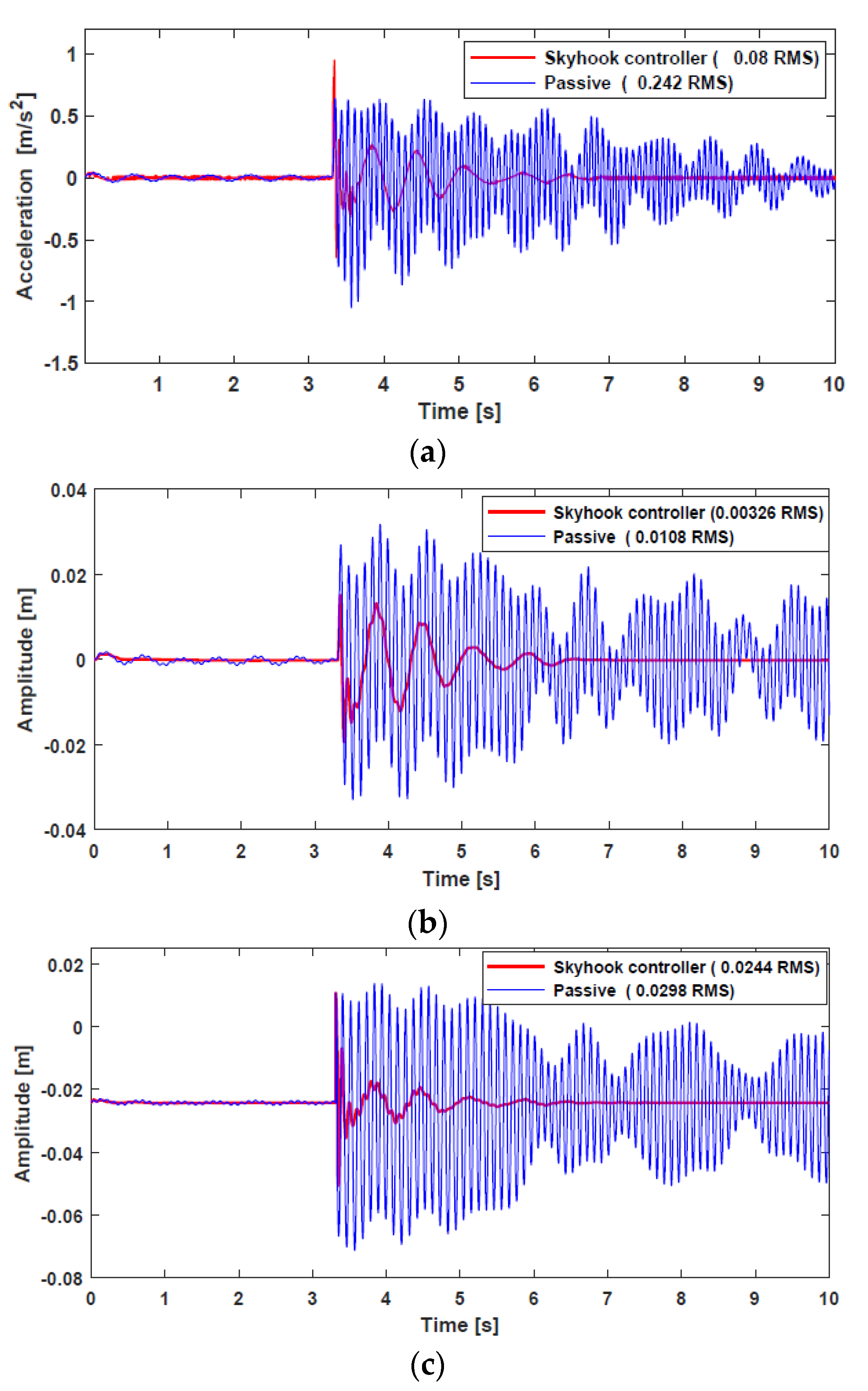
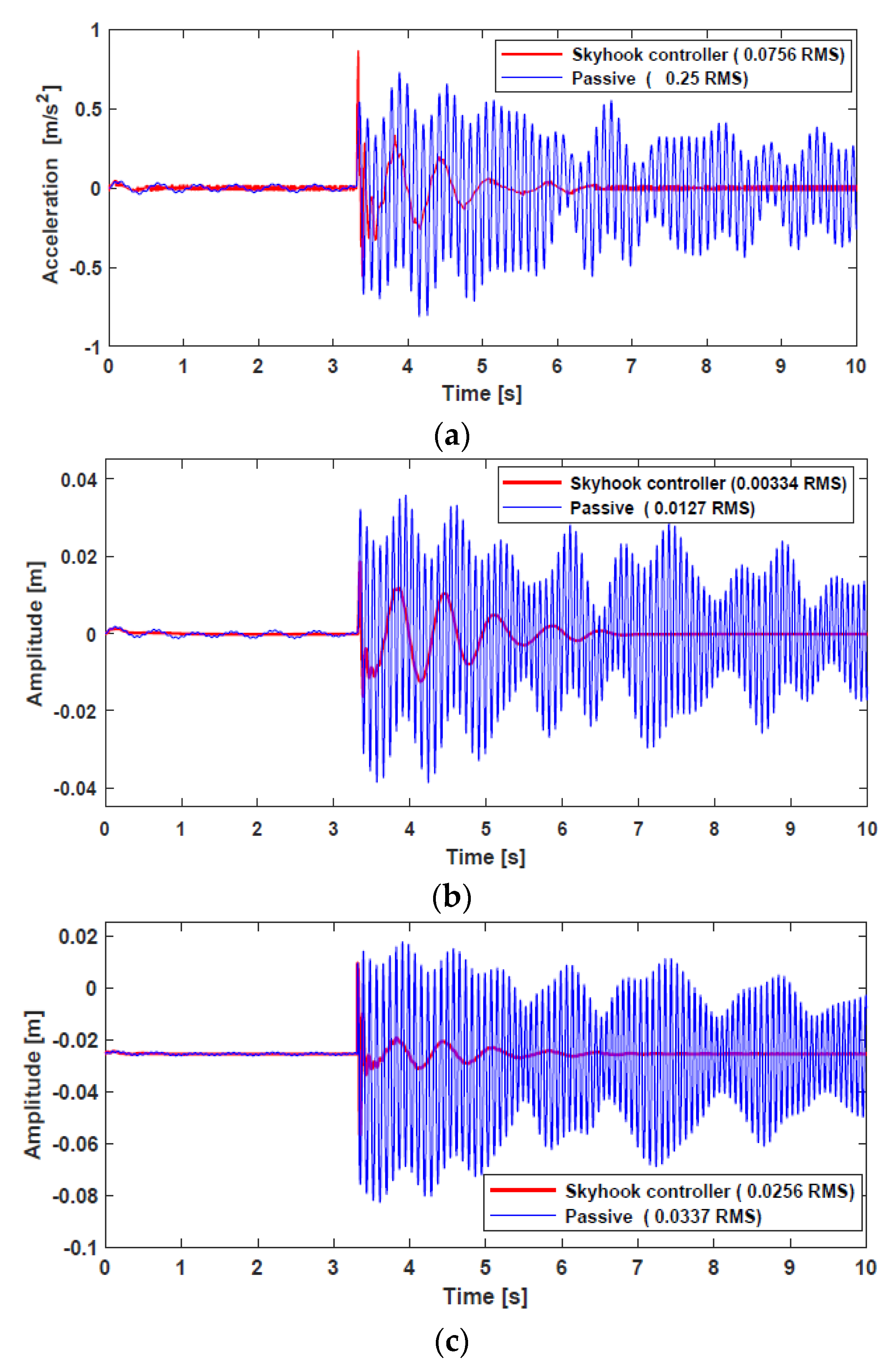
Figure 14 shows the time responses for a vehicle powered by IWM. Evidently, the proposed HARMD attenuates the vibrations for acceleration, suspension deflection, and tire deflection. The difference in responses between a vehicle powered by an engine and another powered by IWMs was insignificant. However, the RMS values for the IWM slightly increased compared with the RMS values for a normal vehicle. The passive RMS values for vertical acceleration, suspension deflection, and tire deflection reduced by 69.76%, 73.7%, and 24.03%, respectively.
According to ISO 2631-1, the ride comfort can be mathematically identified and quantified based on the relative discomfort associated with vehicle motion. The frequency weighted RMS Acceleration calculates how intensive mechanical vibrations affect the human body in vehicles. To quantify the relative discomfort, the frequency weighted RMS acceleration for vertical accelerations was calculated as follows.
where
is the frequency weighted acceleration and
is the exposure time. According to ISO 2631-1, when the frequency weighted RMS acceleration is lower than 0.32, the Discomfort level is “Not uncomfortable”, and when it is greater than 0.32 and less than 0.5, the Discomfort level is “A little uncomfortable”. In the case of a normal vehicle, when the passive damper is used, the frequency weighted RMS acceleration value is 0.42, and when the proposed model is applied, it decreases to a value of 0.18, which satisfies the lowest Discomfort level. Even in the case of the IWM vehicle, when the passive damper is used, the frequency weighted RMS acceleration value is 0.46, and when the proposed model is applied, it can be confirmed that the lowest discomfort level is satisfied by decreasing to a value of 0.16.
In addition, the proposed model was subjected to a random road to test its capability of attenuating random vibrations. Different grades of a random road are used depending on the purpose and type of vehicles. In this study, a grade B random road was selected as the testing road in CarSim, which can be described as follow [
31]
where
represents the road profile,
is the cut-off frequency,
is the spatial frequency,
is the assigned vehicle velocity selected as
,
is the road roughness coefficient, and
is the random white noise. During the simulation, a skyhook controller was used to control the input damping force of each tire. The time responses from the random road are not clear to interpret because of the noise; therefore, the frequency responses obtained from the time domain were used to compare controlled and passive responses.
Figure 15 shows the frequency responses of a vehicle powered by the IWM. The simulation results indicated that the controlled responses outperformed the passive responses in terms of dissipating energy generated from road unevenness. In addition, all the first peak resonances were in the vicinity of frequencies (1–2 Hz). According to ISO 2631 [
32], maximum sensitive vibration to the human body ranges from (4–8 Hz). The RMS values of the body vertical acceleration, suspension deflection, and tire deflection confirm that the proposed damper model has a significant impact on lowering the RMS values compared with the passive values. The power supplied to the semi-active HARMR damper for both bumpy and random road input is illustrated in
Figure 16a,b, respectively. Evidently, the proposed model is efficiently able to suppress the vibration for both bumpy and random roads with the generated current of about 1.7 A and 1.2 A, respectively.


 ,
, 


