1. Introduction
Recently, interest in autonomous driving and connected car has grown because of implementing an intelligent transportation system. Although sensors such as light detection and ranging (Lidar) and cameras can be used to recognize the surrounding environment, vehicle radar technology using millimeter waves is drawing attention as it is not affected by the surrounding environment, such as bad weather or light intensity [
1,
2]. In order to increase the number of sensors fitted to vehicles and to communicate various sensing information and road information, inter-vehicle communication technology with a high data rate is needed. For general vehicle radars, it is important to sense forward-looking vehicles and obstacles, but the resolution of range and azimuth angle is poor with limited frequency bandwidth and limited number of antennas. In addition, it is necessary to consider the potential interference between radar and mobile communication systems in a situation where communication traffic among vehicles increases, also being discussed in 5G mobile communication community [
3].
Due to high-frequency efficiency and ease of interference management, orthogonal frequency division multiplexing (OFDM) radar has been extensively investigated [
4]. In [
5,
6] (and references therein), symbol-based signal processing is proposed to estimate range profile without correlation based baseband signal processing, which also motivates the joint radar and communication (RadCom) systems [
7,
8,
9]. In [
8], the OFDM waveforms carrying the modulated data in each subcarrier are exploited to obtain the range-Doppler map, where the payload data is canceled out in the received OFDM baseband signal at RadCom platform. In [
9], the bistatic RadCom system is developed using OFDM waveforms by exploiting linear array antennas at both transmitter and receiver, and the target parameters (i.e., range, Doppler, and azimuth angle) are estimated by using alternative least squares algorithm. To obtain a two-dimensional (2D) spatial (i.e., range and azimuth angle) radar image, OFDM radar equipped with multiple antennas has been also investigated [
10]. In [
10], a multiple signal classification (MUSIC) algorithm is applied to each range bin for the azimuth angle estimation. However, in the MUSIC algorithm, the estimation of covariance matrix of the received signal is required, which may incur a considerable latency to collect multiple OFDM waveforms at the multiple receive (Rx) antennas. In [
11,
12,
13], compressed sensing-based radar imaging algorithms have been developed for multiple-input multiple-output (MIMO) OFDM radar, not requiring the subspace estimation. However, they do not consider the communication performance when multiple antennas are deployed at RadCom platform.
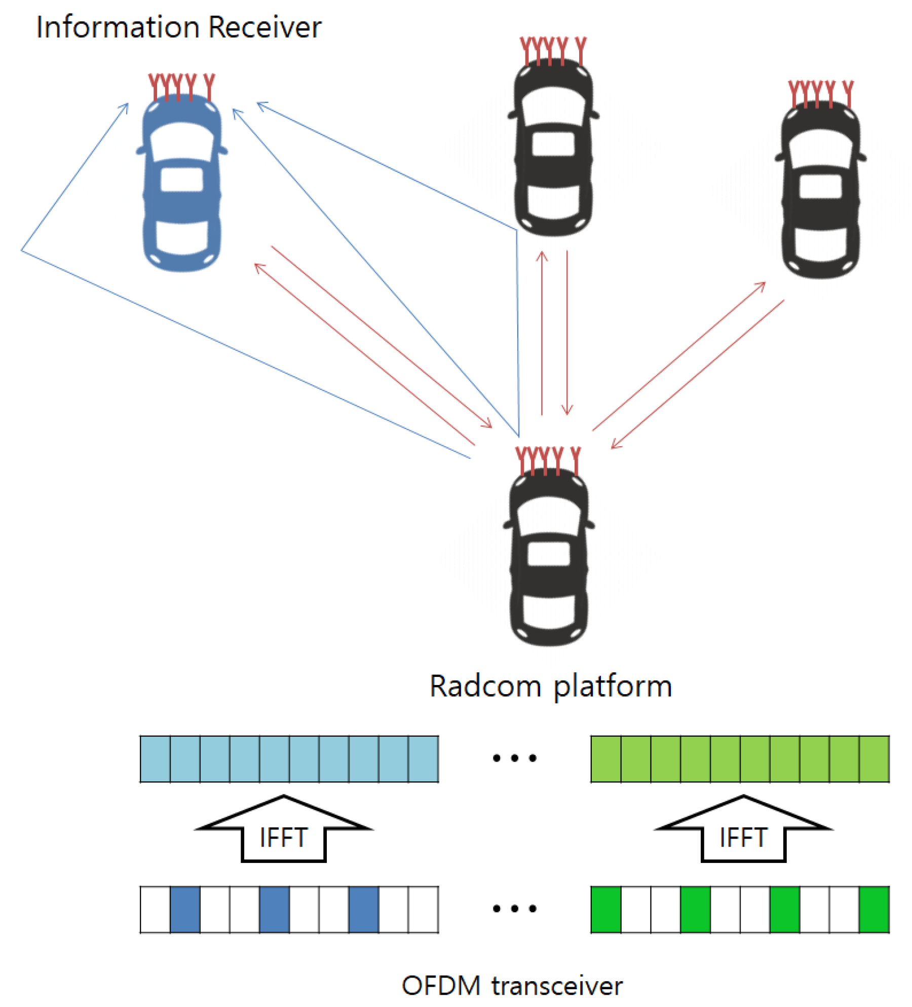
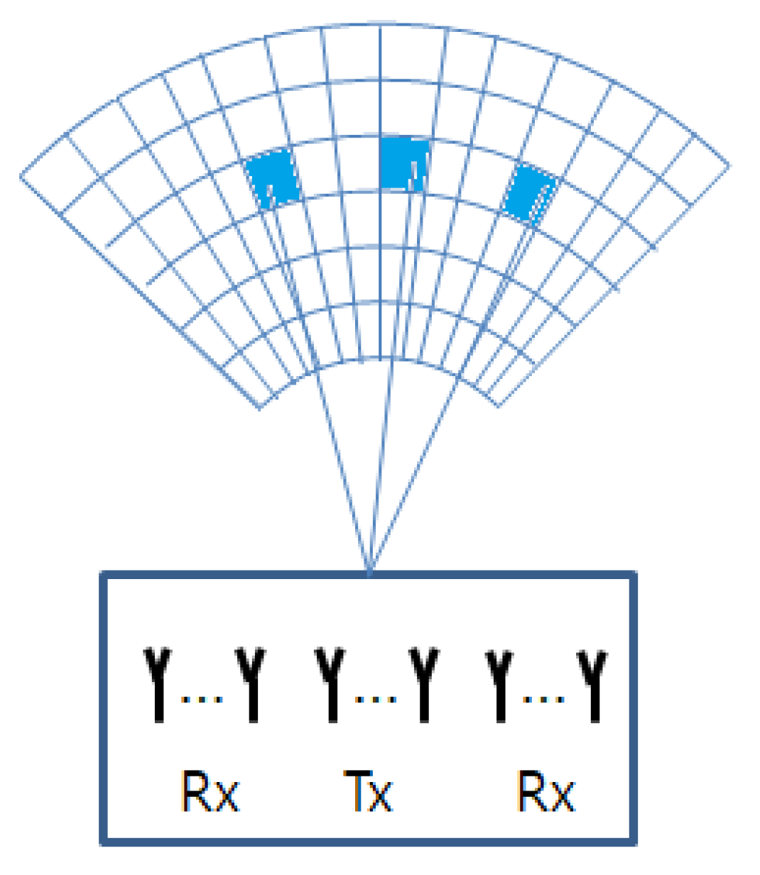
In this paper, by considering the RadCom platform equipped with multiple antennas using OFDM waveform (i.e., MIMO OFDM RadCom platform), we propose the compressive sensing-based radar imaging and the subcarrier allocation methods. Specifically, to get 2D radar images with high resolution, a compressive sensing-based imaging algorithm is first proposed when the subcarriers are orthogonally allocated across multiple transmit (Tx) antennas. Differently from the compressive sensing based estimation for MIMO OFDM radars in [
11,
12,
13], where basis pursuit (BP) or orthogonal matching pursuit (OMP) algorithms are exploited, the Bayesian matching pursuit (BMP)-based imaging method (which is successfully applied to the FMCW MIMO radar system [
14]) is developed for the MIMO OFDM RadCom platform. Because both the mean square error (MSE) of the radar image and the achievable rate are affected by the subcarrier allocation across multiple Tx antennas. Thus, we propose a new subcarrier allocation strategy that efficiently maximizes the achievable rate and simultaneously reduces the MSE of the radar images.
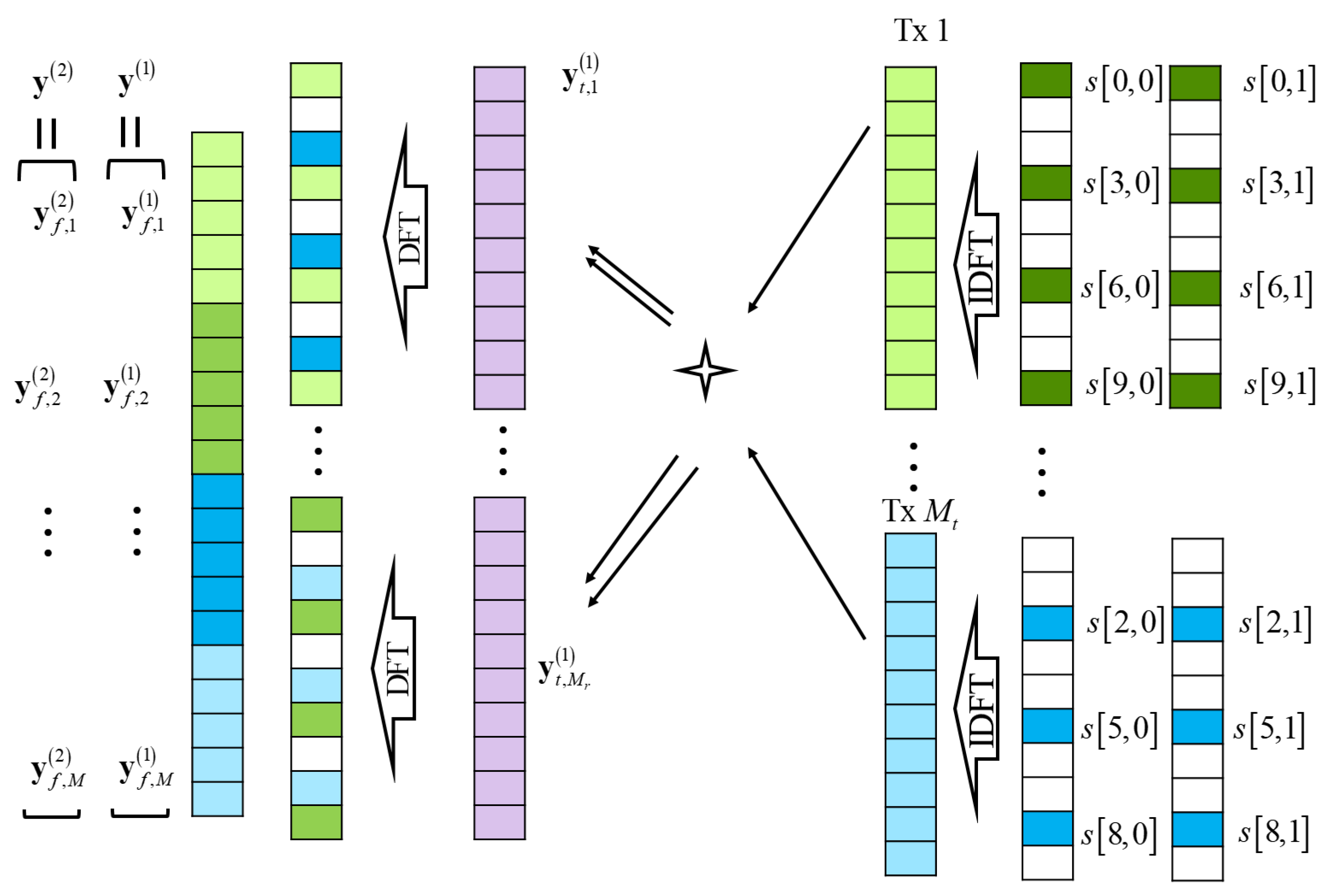
In the proposed BMP-based radar imaging, the received signal at the MIMO OFDM RadCom platform is first transformed into frequency domain to take symbol-based signal processing (i.e., spectral division operation [
15]) and then reformulated in terms of the (azimuth angle, range) patches in the image region of interest. We can then formulate the radar image estimation problem, where the maximum a posterior (MAP) estimate is obtained. In addition, we consider that the RadCom platform transmits information data through OFDM waveforms to the information receiver with multiple antennas, where MIMO channel is established from RadCom platform to the information receiver. Therefore, the achievable rate at the information receiver can be regarded as the communication performance for the RadCom platform. To understand the impact of the subcarrier allocation on the MSE, we analyze the lower bound of Cramer–Rao lower bound (CRLB) in our radar image estimation with three different subcarrier allocation methods—equi-space subcarrier allocation, block-wise subcarrier allocation, and pseudorandom subcarrier allocation. Based on the analysis, we propose a new subcarrier allocation strategy that efficiently maximizes the achievable rate and simultaneously reduces the MSE of the radar images. We also discuss how the Doppler frequency of the targets in 2D radar image can be estimated by exploiting the output of our radar image estimation problem. Through computer simulations, our BMP-based method exhibits radar images with higher resolution, compared to the conventional back-projection-based imaging method [
16]. In addition, it is also verified that through the proposed subcarrier allocation strategy, a high achievable rate is obtained without sacrificing the radar imaging performance.
The rest of this paper is organized as follows. In
Section 2, the system model for MIMO OFDM RadCom platform is introduced. In
Section 3, the BMP-based radar imaging with MIMO OFDM waveform is proposed, where the received signal is processed with the frequency-domain OFDM signal processing at RadCom platform. Then, it is reformulated in terms of the (azimuth, range) patches and is cast in the sparse radar image reconstruction problem. In
Section 4, information transfer using MIMO OFDM waveform is explained and the achievable rate maximizing transmission strategy is developed. In
Section 5, the subcarrier allocation strategy considering both the radar performance and the communication performance is proposed. In
Section 6, the Doppler frequency estimation from the estimated 2D radar image results is presented. In
Section 7 and
Section 8, the simulation results and conclusion are presented.
4. Information Transfer Using MIMO OFDM Waveform
For information transfer, the QAM signal is carried on the subcarriers of the transmitted OFDM waveform as in (
1), and to demodulate QAM signal, the discrete-time received signal for the
th information Rx antenna in (
8) should be transformed into the frequency domain as
To maximize the achievable rate at the information receiver, the maximal ratio combining (MRC) scheme is used at each subcarrier. Specifically, by denoting
, the MRC output can be given as the weighted sum of the frequency-domain received signals with a weight vector,
. The output of the MRC can then be given as
From (
6) and (
21), the achievable rate at the information receiver can be derived as
We note that the pilot frequency selection does not affect the radar imaging, because the transmit symbols are known at the RadCom platform. In contrast, the pilot frequency selection affects the channel estimation at the information receiver [
23]. Even though we analyze the theoretic achievable rate, assuming the perfect channel state information at the receiver, by focusing on the effect of the subcarrier allocation on both radar and communication performances in
Section 5, the analysis of the achievable rate considering the pilot frequency selection and the channel estimation error is an important topic but is out of scope of this paper.
5. Subcarrier Allocation Strategy
We note that both the radar imaging and the communication performances are dependent on how the subcarriers are allocated to multiple Tx antennas. In our RadCom system, the MSE of radar image in (
13) (i.e.,
) and the achievable rate in (
23) are, respectively, considered as the radar imaging and the communication performance measures, and the subcarrier allocation method is equivalent with the determination of
for
and
under the constraint (
6).
For the communication performance, the achievable rate in (
23) can be maximized by allocating each subcarrier to the Tx antenna with the maximum channel gain on that subcarrier. That is, the achievable rate maximization strategy can be given as
and
otherwise. However, when the coherent channel bandwidth is large (i.e., the delay spread is small), subcarriers may be intensively allocated only to specific Tx antennas, which is not desirable to the radar imaging. In extreme case, if all subcarriers are allocated only to a single Tx antenna, the azimuth angle resolution disappears.
Note that the matrix
in (
13) is implicitly dependent on the subcarrier allocation, but its effect on the MSE of radar image is subtle and difficult to analyze. Instead, the CRLB of MSE is considered. In [
24], assuming that the support set is known, the MSE of the compressive sensing problem is lower bounded by
where
is a sub-matrix of
that consists of the columns associated with the indices of
. Unfortunately, it is still computationally prohibited to find optimal
for
and
such that (
25) is minimized.
To shed light on the idea, in
Table 1, the average CRLBs for the three different subcarrier allocation methods (equi-space, block-wise, and pseudorandom methods) with random support sets
are listed, when
,
,
,
kHz, and
. In the equi-space subcarrier allocation, the
th subcarriers,
, are allocated to the
th Tx antenna. In the block-wise subcarrier allocation, the
th subcarriers,
, are allocated to the
th Tx antenna. Note that, for simplicity, it is assumed that
is a multiple of
. In the pseudorandom subcarrier allocation, the
subcarriers are randomly allocated to each Tx antenna. From
Table 1, the equi-space allocation method exhibits lower CRLB than other methods, which implies that when the subcarriers are regularly allocated to Tx antennas,
in (
13) can project the sparse
onto the received signal
and reduce the MSE; that is, it is advantageous to keep the frequency spacing some distance apart for the subcarriers allocated to the same Tx antennas.
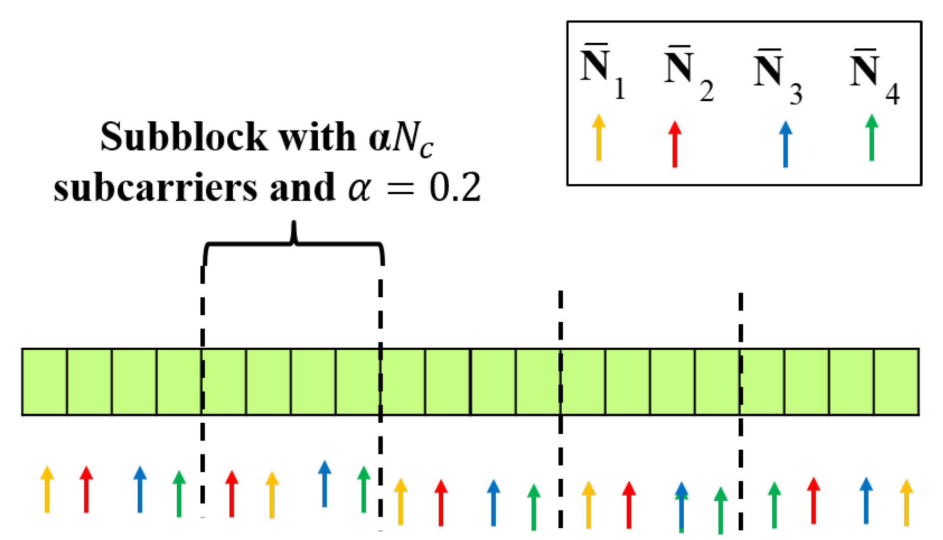
Motivated from the above observations, the subcarrier allocation strategy considering both the communication and radar imaging performances is proposed. Here, to avoid unbiased allocation of subcarriers to a specific antenna, the number of subcarriers allocated to each antenna is set to have the same number. That is,
for
. To guarantee the frequency spacing for the radar imaging,
subcarriers are first divided into multiple sub-blocks with
subcarriers, where
such that
and
are integers (For ease of explanation, we confine the value of
, but it can be extended to the general cases that
and
are not integers). Then, the number of the sub-block is given as
, and the subcarriers within the same sub-block are allocated to the Tx antenna so that its associated channel gain is maximized, which is done similarly in (
24). By defining
as
the above explained process is summarized as Algorithm 1.
In
Figure 4, an example of the operation of the proposed strategy is shown when
,
, and
. Within the same block, the subcarriers are allocated such that the achievable rate is maximized. Furthermore, it is possible to ensure a frequency space of at least
on average between subcarriers from different sub-blocks allocated to the same Tx antenna. Specifically, by dividing the subcarriers into multiple sub-blocks, the subcarriers within the same sub-block can be allocated to the Tx antenna so that its associated channel gain is maximized. In addition, limiting the number of subcarriers that can be allocated to the same antenna within the same sub-block prevents consecutive subcarriers from being assigned to a specific antenna. We note that the proposed radar imaging and the subcarrier allocation methods can be applied to the OFDM waveforms having the null bands without difficulty.
| Algorithm 1 Subcarrier allocation method for a given |
- 1:
- 2:
for - 3:
- 4:
for , - 5:
do - 6:
- 7:
- 8:
do - 9:
- 10:
if then - 11:
- 12:
, - 13:
- 14:
end if - 15:
- 16:
while for any - 17:
while
|
Interestingly, for a large
, the subcarriers are more likely to be assigned to the Tx antenna with larger channel gains, but
consecutive subcarriers within the same block may be allocated to the same Tx antenna in the worst case. Increasing
is advantageous in terms of communication performance, and vice versa. We also note that the case with
is equivalent with the achievable rate maximization strategy in (
24) with the constraint of the number of subcarriers per antenna (i.e.,
for
). Accordingly, the proposed subcarrier allocation method encompasses both communication and radar performances and, by adjusting
, the radar/communication performances can be properly balanced.
6. Discussion: Doppler Frequency Estimation
In
Section 3, the 2D spatial radar image is obtained from a single backscattered MIMO OFDM pulse. To estimate the Doppler frequency of the target, multiple pulses should be collected in a coherent time duration. Accordingly, it is considered that
. To estimate the Doppler frequencies of the targets detected in a 2D radar image, a FFT-based Doppler estimation method can be exploited.
By denoting the radar image estimate obtained from the
th radar echo signal (i.e.,
) as
, its nonzero element position corresponds to the target position in the 2D radar image from (
12) and (
13). Accordingly, the target location patch index set can be given as
where
is a predefined threshold. Then, to estimate the Doppler frequency of the target associated with the patch
j in
, the received signal is matched filtered, which is given as
where
, and
is the residual term containing the received echo signal not co-phased with the
jth column of
(i.e.,
) and the noise. Then, the Doppler frequency of the patch
j can be estimated by using FFT operation as
and the associated velocity is given by
.
7. Simulation Results
Computer simulations have been performed to verify the proposed scheme. In the simulations, the number of subcarriers is set as
with the subcarrier space,
kHz, and the carrier frequency (
) is given as 30 GHz. In addition,
= 12.5 s and
= 50 s. In addition, the received SNR is defined as
where
is the variance of the Gaussian noise.
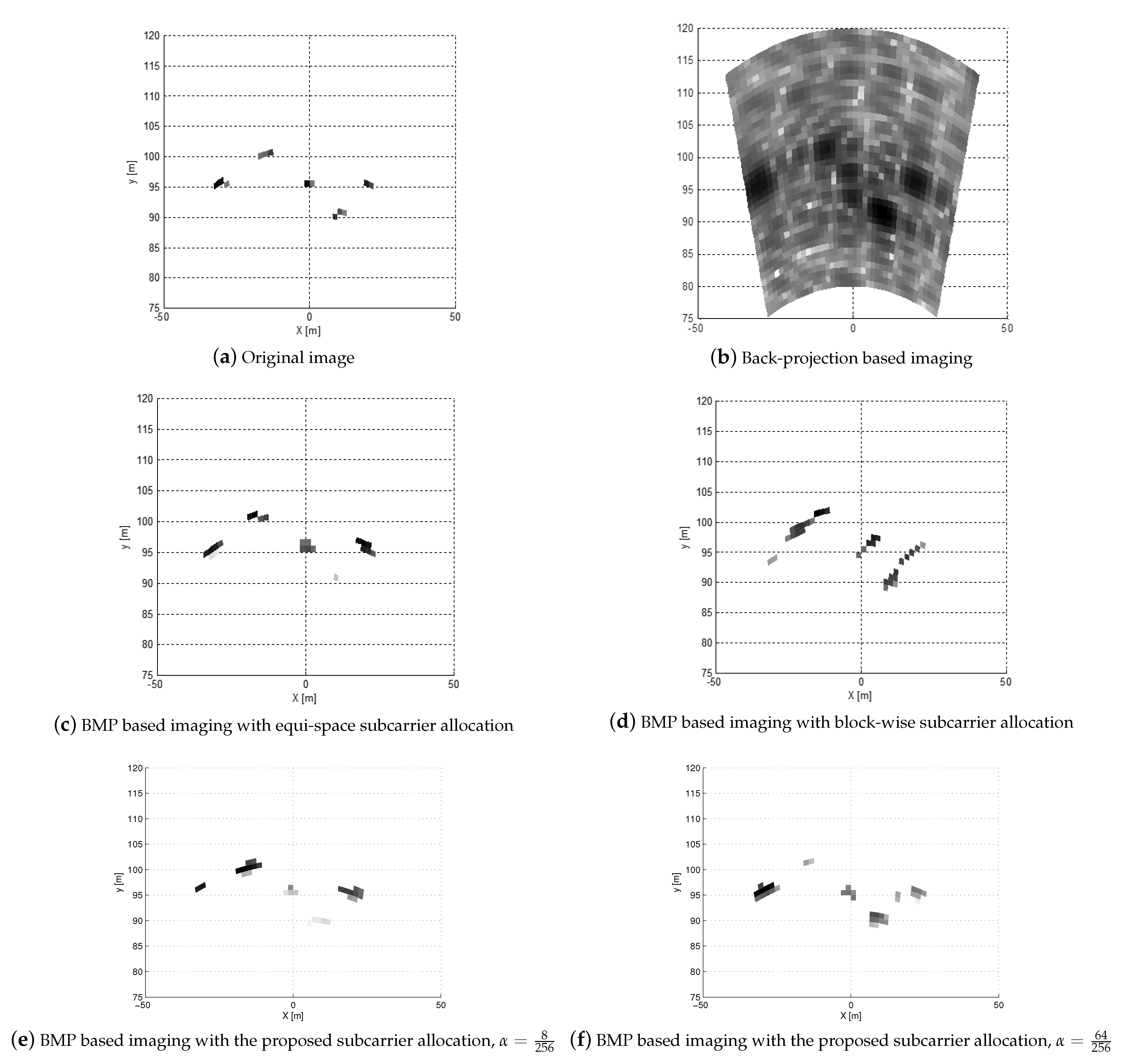
In
Figure 5, the radar images obtained from the proposed BMP-based MIMO OFDM radar imaging algorithm at
dB are displayed. For the reference, in
Figure 5a, the original image is also provided. Specifically, five targets are in the radar image region of interest (
), and each target consists of 85 point scatterers with a size of 4 m × 1 m. In addition, the numbers of the Tx and Rx antennas at the RadCom are set as
and
, respectively. The size of each patch is given as
, which implies that
and
. If we decrease the pixel size, we can improve the image resolution, but the number of elements in
in (13) increases. Accordingly, the number of measurements (i.e., the dimension of
) should be increased proportional to the number of nonzero elements in
.
In
Figure 5b, the radar image obtained by the back-projection method (i.e.,
) is shown. From the figure, the back-projection method exhibits poor resolution in both azimuth and range directions, that is, the targets in the radar image are severely blurred. The radar images of the BMP-based MIMO OFDM radar imaging with equi-space subcarrier allocation and block-wise subcarrier allocation are, respectively, shown in
Figure 5c,d. It can be found that the BMP-based imaging with equi-space subcarrier allocation gives a better target image than back-projection method. However, when block-wise subcarrier allocation is exploited, some distorted target pixels can be found. In
Figure 5e,f, the radar images of the BMP-based MIMO OFDM radar imaging with the proposed subcarrier allocation with
are given. From the figures, when the proposed subcarrier allocation method is exploited, five targets are more clearly found, compared to that with the block-wise subcarrier allocation.
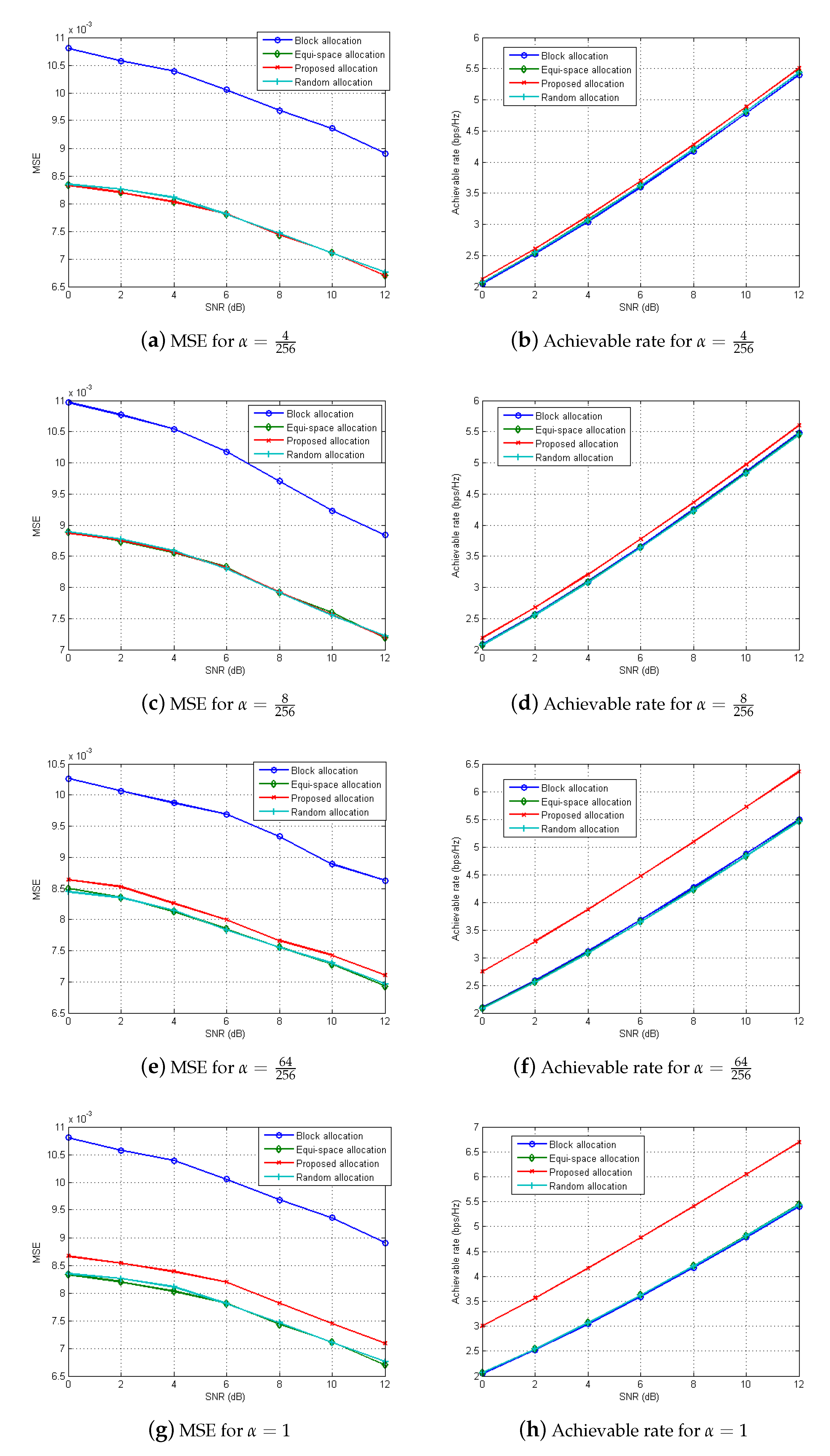
To evaluate the performance of the proposed subcarrier allocation strategy for the RadCom, Monte Carlo simulations are also carried out with various
in
Figure 6. Here, the number of multipaths is set as
for the information channel link, and each path is set as a zero-mean complex Gaussian random variable with a unit variance. For the RadCom performance, we evaluate the MSE of the radar image, given as
, and the achievable rate at the information receiver. For comparison purpose, the performances of three different allocation methods (equi-space, block-wise, and pseudorandom methods) are also evaluated. From the figure, block-wise subcarrier allocation method shows the worst MSE performance, while equispace and pseudorandom subcarrier allocation methods have similar MSE performances, which coincides with the discussion in
Section 5; that is, when subcarriers are evenly allocated across the entire band for each antenna, the radar performance can be improved. We note that the achievable rates of those three methods are similar, because they do not consider the communication performance at all.
From the figure, it can be found that when increases, both the MSE and the achievable rate of radar images increase. That is, for small , subcarriers for each antenna tend to be evenly allocated over the entire band. In contrast, for large , the subcarriers are more likely to be assigned to the Tx antenna with larger channel gains, which results in the increase of the achievable rate. Specifically, for , the proposed subcarrier allocation exhibits a slight performance degradation in MSE performance, but an approximately 16% increase in the achievable rate is achieved compared to the equi-space allocation method. Accordingly, by adjusting , the radar/communication performances can be properly balanced.
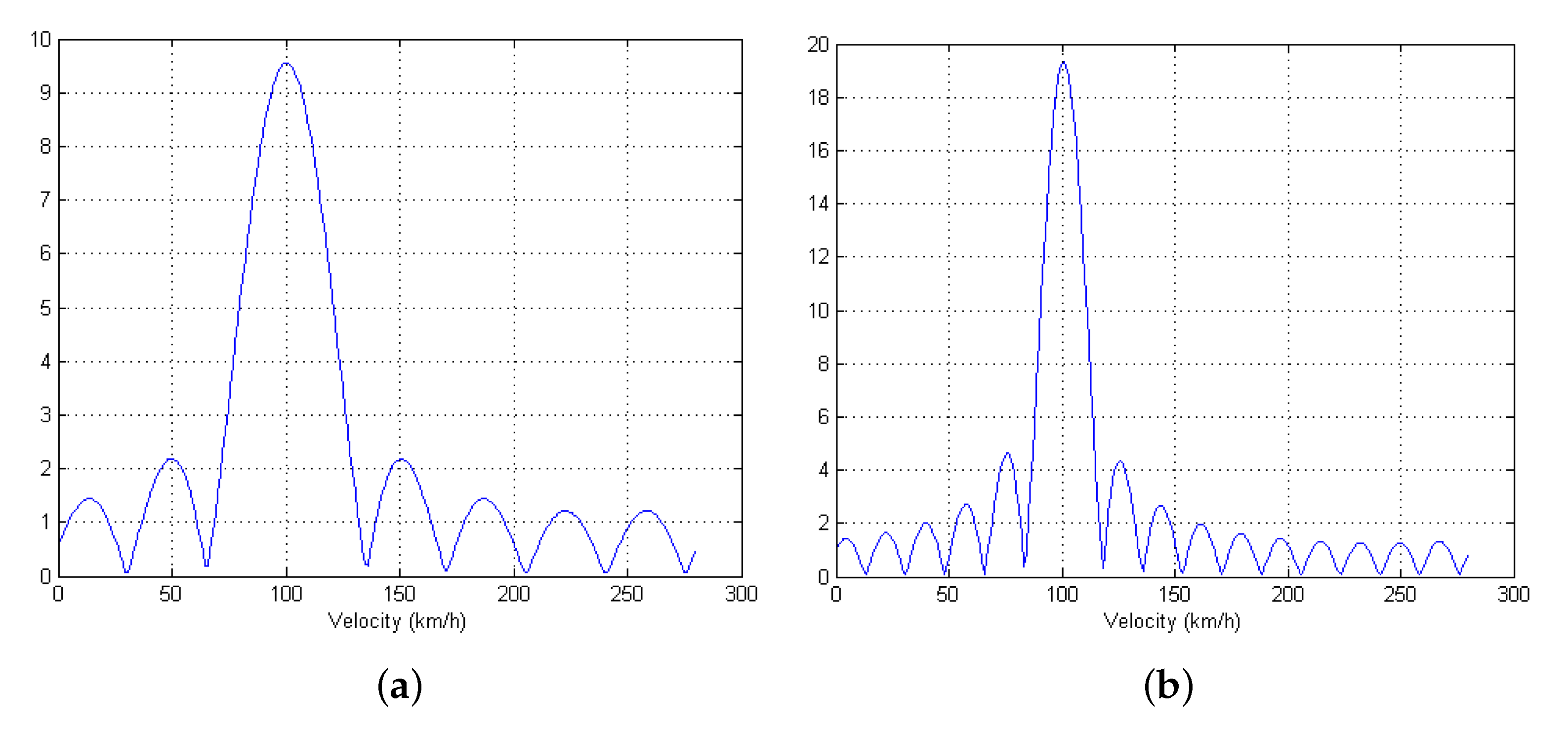
To verify the Doppler estimation method discussed in
Section 6, when the radial velocity of a target is set as 100 km/h, the Doppler frequency profile (
in (
28)) is displayed in
Figure 7 for
. From the figure, it can be found that the peak position coincides with the radial velocity of the associated target, and the resolution can be improved as the number of pulses increases, which is also induced from (
28).


