1. Introduction
1.1. CR Networks with RF Energy-Harvesting
To fulfill ever-increasing demands for wireless services and applications, cognitive radio (CR) technology has been emerged to lighten severe shortage of spectrum resources [
1]. CR technology allows the secondary users (SUs) to access the spectrum licensed to the primary users (PUs), based on the premise that the quality of service (QoS) requirement of the PUs must be guaranteed [
2,
3]. In the CR networks, underlay and overlay are two main schemes that the SUs share the spectrum with the PUs [
4,
5]. In the underlay paradigm, the SUs transmit concurrently in the same spectrum with the PUs, if the interference caused by the SUs to the PUs is below a given threshold. On the other hand, the explosion of wireless services and applications has also led to energy deficiency in the future wireless communications. Radio-frequency (RF) energy-harvesting technology is a good candidate solution for charging the low-power wireless devices [
6,
7,
8,
9,
10], which can conquer the uncontrollability and intermittency of wireless devices powered by the renewable energy sources, such as wind, solar and vibrational energy. The harvest-then-transmit (HTT) protocol is proposed in [
11] as one of the most common working mode of RF energy-harvesting technology, where the users first harvest energy from the RF energy source in the energy transfer (ET) phase and then use the captured energy to transmit information to the destination in the information transfer (IT) phase.
In order to simultaneously improve the energy efficiency and spectrum efficiency mentioned above, the use of RF energy-harvesting technology in CR networks has been studied extensively in the literature [
12,
13,
14,
15,
16,
17]. In [
12], the authors presented an overview of RF energy-harvesting CR networks, where the SUs can capture energy from the PUs transmissions and transmit information when the channel is vacated by the PUs. The authors in [
13] investigated the end-to-end throughput maximization problem by jointly optimizing the power and time allocation for the underlay CR networks. An underlay multi-hop CR networks with RF energy-harvest SUs was also considered in [
14], where the authors derived the expressions of throughput and end-to-end outage probability. In [
15], the authors studied optimal sensing intervals for an overlay RF energy-harvesting CR networks, where the unslotted PUs was considered. The authors in [
16] found the optimal sensing policy to maximize the SU throughput subject to the energy constraint of the SU. In [
17], the authors integrated ambient backscatter communication into RF energy-harvesting CR networks, where the analytic expressions for the average energy consumption, average achievable throughput and energy efficiency were derived.
1.2. Achieving Physical Layer Security of Wireless Networks
Besides the spectrum efficiency and energy efficiency, wireless communications are also facing the challenge of being wiretapped by the malicious eavesdroppers, due to the intrinsic broadcast nature of wireless medium. Physical layer security (PLS) is a promising solution to achieve the secure communication by exploiting physical properties of wireless channels, e.g., noise, fading, interference, etc [
18]. The general goal of PLS is to maximize the secrecy rate, which is defined as the capacity of the main channel minus that of the wiretap channel.
To enhance physical layer security, various techniques have been investigated in past decades, such as multiple-antenna technology, relay, and cooperation [
19,
20,
21,
22,
23,
24,
25], etc. Cooperative jamming (CJ) as a practical approach among them has drawn much attention recently, which uses friendly jammer to generate jamming signals to impair the illegal link. The CJ strategy was proposed in [
23] to deal with eavesdroppers anywhere in the wireless networks, where the jammer placement algorithms were analyzed. The authors in [
24] maximized the secrecy rate at the destination under the transmit power constraints for the amplify-and-forward (AF) relay and the harvest-and-jam (HJ) helpers, where the multi-antenna HJ were used in a multi-antenna AF relay wiretap channel. Motivated by the RF energy-harvesting technology, the authors in [
25] considered wireless powered jammer to secure the downlink communication from the source to the destination, where the jammer first harvested energy from the source and then generated jamming signals to the potential eavesdropper. The secrecy rate was maximized by jointly optimizing the time and power allocation. The wireless powered jammer was also introduced in [
26], where the authors considered the secrecy rate and secrecy outage probability according to the level of channel state information (CSI) of the eavesdroppers, respectively.
1.3. Achieving PLS of CR Networks
In addition, CR networks are also vulnerable to malicious eavesdropping, which have drawn significant attention. The authors in [
27] studied the spectrum access method and the PLS of CR networks, where some mathematical expressions for PLS performance metrics were derived. The authors in [
28] proposed a game theory to optimize the secondary secrecy rate and the primary secrecy rate in CR networks, where the SU transmitted jamming signals for both the primary transmission and secondary transmission. In [
29], the primary transmission privacy was guaranteed by introducing a wireless powered secondary jammer. Contrary to [
29], the secondary transmission secrecy against eavesdropping by PUs was considered in [
30]. Different from the conventional single-carrier CR networks, the authors in [
31] considered secrecy energy efficiency (SEE) problem for a orthogonal frequency division multiplexing (OFDM)-based CR networks, where the instantaneous channel state information (ICSI) of the eavesdropper and the statistical CSI (SCSI) of the eavesdropper were both considered.
To date, few works have been done on PLS of RF energy-harvesting CR networks. Inspired by this, we investigate the PLS of underlay CR networks, where the SU and secondary jammer (SJ) harvest energy from the PU transmissions. The differences between our work and the previous woks [
28,
29] are summarized as follows: (a) The authors in [
28,
29] consider overlay CR networks with one PU, while we focus on underlay CR networks with one PU as well as multiple PUs. (b) In [
28,
29], the SU transmits artificial noise (AN) to confuse the eavesdropper, while a wireless powered cooperative jammer is introduced in our work to impair the wiretap channel. (c) The authors in [
29] consider the secure transmissions for the primary network and the authors in [
28] investigate secure transmissions for both the primary and secondary networks, while we study the secure transmission for the secondary networks. The main contributions of this paper are summarized as follows.
We propose communication schemes for the underlay CR networks with one PU as well as multiple PUs. The SU and SJ first capture energy from the PU transmissions. Then, the SU transmits confidential information to the secondary receiver (SR), and the SJ simultaneously transmits jamming signals to confuse the eavesdropper. We study the secrecy rate maximization problem for the secondary network by jointly optimizing the time allocation between ET phase and IT phase, and the transmit power allocation for SU and SJ. We formulate the original problems as optimization problems which are non-convex.
We design efficient nested form algorithms for both non-convex problems. In the outer layer, the time allocation is obtained by the one-dimension search approach. In the inner layer, the transmit power allocation is obtained by the DC programming, where the Lagrange duality method is employed to solve the convex approximation problem.
Simulation results are given to verify the superiority of the proposed schemes as compared to the benchmark schemes. Moreover, we observe the impact of system parameter settings on secrecy performance.
2. System Model and Problem Formulation for Underlay CR Networks with One PU
2.1. System Model
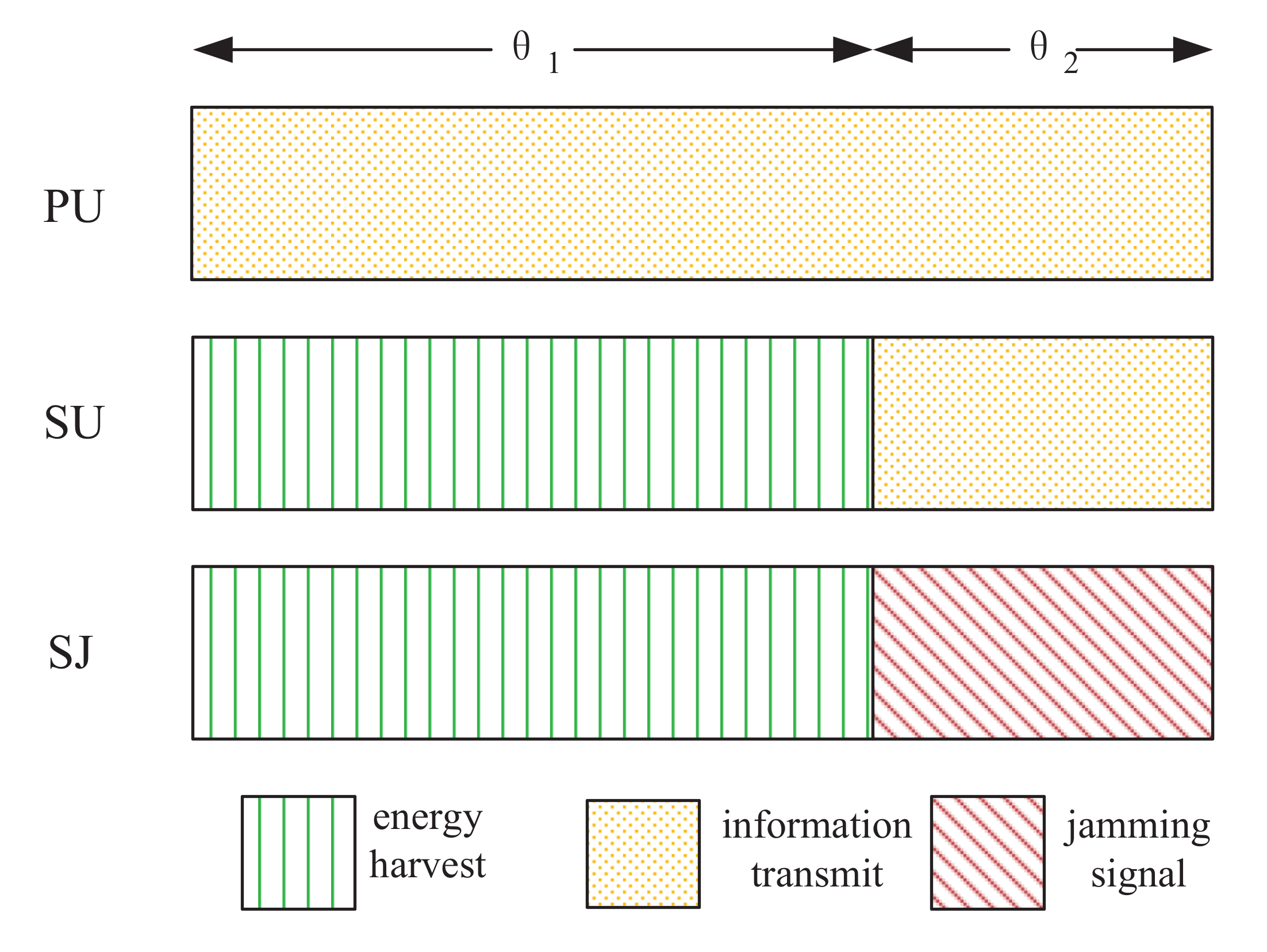
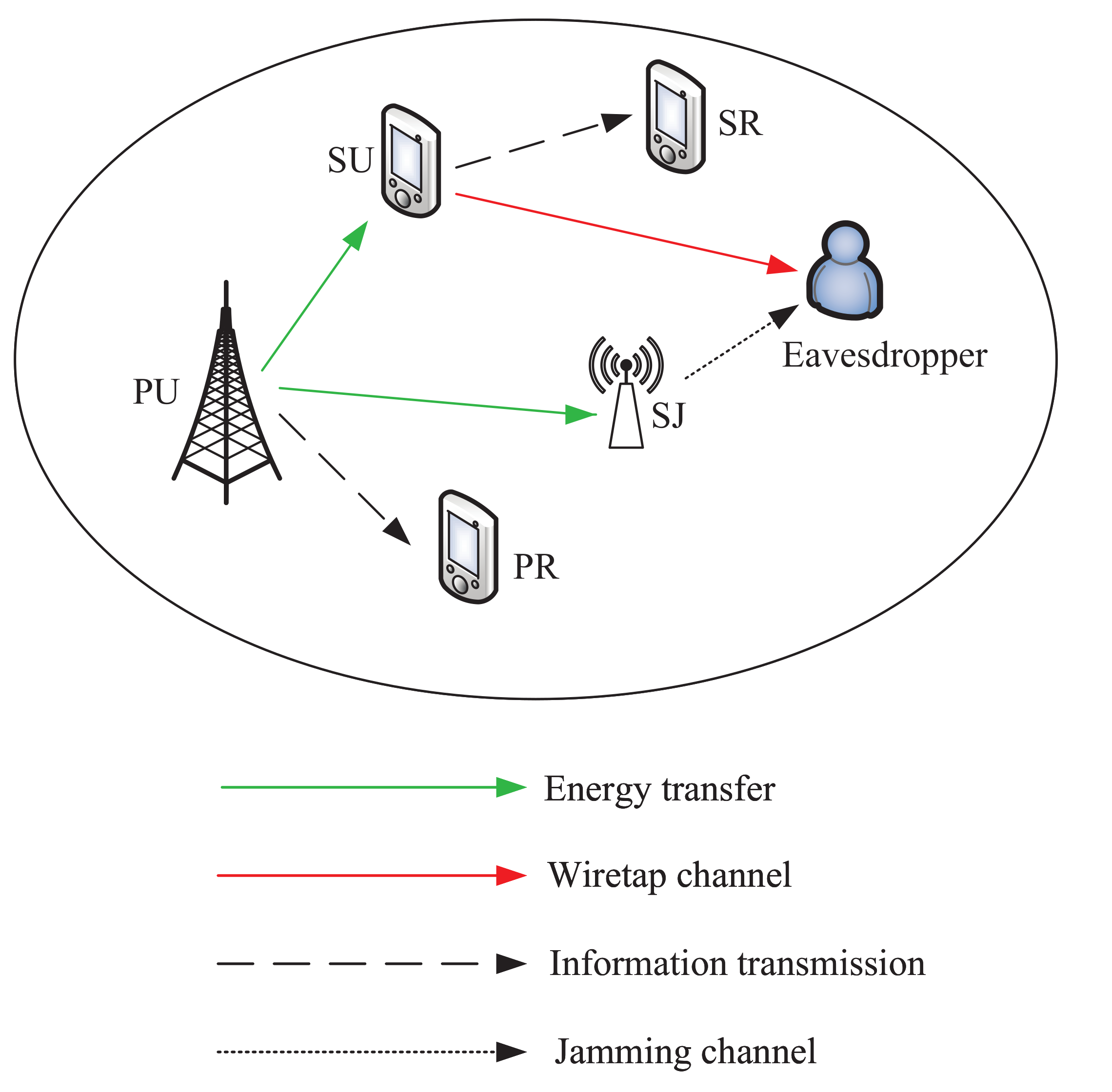
The considered underlay CR networks is shown in
Figure 1. The primary network consists of a PU licensed with spectrum, and a corresponding primary receiver (PR). In the secondary network, SU transmits information to a secondary receiver (SR) by accessing the PU spectrum, if it does not cause the harmful interference to the PU transmissions, where the confidential information is threated by a potential eavesdropper. We employ a SJ to secure the secondary network. SU and SJ have no embedded power supply, which need to harvest energy from the PU transmissions in the ET phase. We consider a block-based quasi-static channel model where the CSI remains constant over each time block, but changes from one time block to another. Specially, the CSI can be obtained via efficient channel estimation and feedback methods. Without loss of generality, we assume that the time block T is 1 s.
The specific block structure diagram can be referred to
Figure 2. In the entire time block, PU transmits information to PR with a fixed power
. Furthermore, the entire time block is divided into two phases with lengths
and
, which denote the ET phase and IT phase, respectively. Therefore, the time constraint should satisfy
Specially, the SJ keeps synchronously with the SU. That is, for SU and SJ, ET phase and IT phase must be consistent. In the EH phase, SU and SJ harvest energy from the PU transmissions. The energy harvested by the SU is expressed as
where
and
denote the energy harvesting efficiency at the SU and the channel power gain from the PU to SU, respectively. Similarly, the energy captured by SJ is expressed as
where the energy harvesting efficiency at SJ is assumed to be the same as the SU [
25,
26], and
denotes the channel power gain from the PU to SJ.
In the IT phase, the SU uses the harvested energy
to transmit privacy information to SR. The total energy consumed by the SU to transmit information should satisfy
where
denotes the transmit power at the SU. To guarantee the QoS requirement of the PU, the transmit power at the SU should be below a given threshold
I, which is given by
Meanwhile, the SJ simultaneously utilizes the captured energy
to generate the jamming signals to the eavesdropper against its eavesdropping. The total energy consumed by the SJ to generate jamming signals should satisfy
where
denotes the transmit power at the SJ. To guarantee the QoS requirement of PU,
should also be below a given threshold
I, which is expressed as
Based on the above analysis, the throughput
at SR and the throughput
at the eavesdropper, are expressed as
and
where
W is the bandwidth,
and
denote the noise power at the SR and the eavesdropper,
,
and
denote the channel power gains from SU to SR, SU to the eavesdropper, and SJ to the eavesdropper. Here, the CSI of the eavesdropper can be obtained by monitoring the possible transmissions of the eavesdropper as is commonly used in the PLS literature [
25]. We assume that the jamming signals from the SJ is known at the SR, which means that the SJ interference can be removed at the SR [
25,
26].
Therefore, the secrecy rate of the secondary network is given by
where
.
2.2. Problem Formulation
We target to maximize the secrecy rate in (10), subject to the time constraint in (1), the transmit power constraints in (5) and (7), and the energy causality constraints in (4) and (6). The decision variables include the time allocation
and
, the transmit power allocation
at the SU, and the transmit power allocation
at the SJ. Then, the secrecy rate maximization problem is formulated as
Note that problem (P1) is non-convex as its objective function is non-concave. As a result, it is difficult to tackle in general.
3. Secrecy Rate Optimization Design for Underlay CR Networks with One PU
Firstly, we give Lemma 1 to reveal the property of the optimal time allocation solution.
Lemma 1. The optimal time allocation solution of problem (P1) uses up the entire time block, i.e.,
Proof. Assume that the optimal time allocations of and satisfy . Let us construct another new solution {, , , }, with and , where . So . Note that {, , , } is also a feasible solution of problem (P1), which satisfies (1), (4), (5), (6) and (7). From (8), (9) and (10), we can see that when the IT phase is larger, the secrecy rate , which contradicts to the assumption. Thus, we complete the proof. □
Considering the non-convex of problem (P1), we solve it by formulating it into a nested form as
where
is expressed as
Here, for the outer layer (12), the optimal time allocation
can be obtained through one-dimensional search. When
is given, we tackle the inner layer (13) to obtain the optimal transmit power allocation at SU and SJ. It is obvious that (13a) is monotonically increasing with respect to
. Meanwhile, considering the energy causality constraint in (13d) and transmit power constraint in (13e), the
can be replaced by
, which is given by
For the convenience of description, we utilize Logarithmic conversion formula
to re-write (13) as
Specially, can be removed from (15) as it does not affect the analysis results of the original problem. Then, (15) is re-expressed as . It is observed that both and are concave. Thus, (15) can be represented as concave function minus concave function, which obviously corresponds to the difference of concave (DC) function. Theoretically, the optimal solution of such objective function can be obtained by DC programming, which is to successively solve the first-order Taylor approximation of the original problem.
3.1. DC Programming for (P3)
Based on DC theory, in order to convert the objective function of problem (P3) to an approximate convex problem, first-order Taylor approximation is used to approximate concave function
into linear form. Then, at the (
k + 1)-th iteration of DC programming, let
be substituted by its first-order Taylor approximation expression as shown below
where
denotes the optimal transmit power at SU at the
k-th iteration of DC programming, which will be used for the
-th iteration.
The objective function of (P3) is re-rewritten by replacing
with its first-order Taylor approximation expression represented at (16) and removing the constant terms. Then, we have
In the objective function (17) of problem (P4), the first term is concave, the second term is constant, and the third term is linear with respect to , thus the objective function of problem (P4) is concave. Moreover, the constraints (13b) is affine, and (13c) is explicit constraint. Therefore, problem (P4) is a convex optimization problem. Based on DC programming, as the number of iteration increases, the objective function (17) of problem (P4) can successively converge to the original function.
3.2. The Lagrange Dual Method for (P4)
For each iteration in DC programming, we use Lagrange dual method to solve problem (P4). For convenience, we first make one substitution. Let
The partial Lagrangian of (17) is given by
where
is the dual variable associated with the constraint (13b). The dual function is given by
When
is given, we can obtain the optimal solution of
as follows. The derivative of (19) with respect to
is expressed as
and by setting (21) to zero, we have
Considering the transmit power constraint in (13c), the optimal solution of
is expressed as
In order to minimize
, we use the sub-gradient method to update the Lagrange multiplier, which is given by
where
is the step-size,
is the optimal power allocation at the
l-th iteration. Thus, we can obtain the optimal Lagrange multiplier and the optimal transmit power allocation at SU and SJ, which are denoted by
,
and
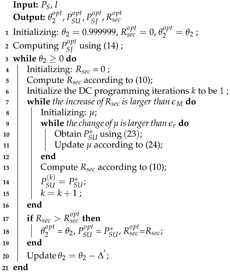
, respectively. Above all, Algorithm 1 summarizes the process of finding the optimal solution of problem (P1).
| Algorithm 1: Optimal time allocation and transmit power allocation for (P1) |
![Sensors 21 08198 i001]() |
3.3. Computation Complexity
The computation complexity of Algorithm 1 is , which is explained below. In the outer layer, the computation complexity of one-dimensional search can be ignored, because it is constant. Denote the number of iteration for the DC programming by . At each iteration, the sub-gradient method is used to obtain the optimal transmit power allocation for problem (P4), which has the complexity .
4. System Model and Problem Formulation for Underlay CR Networks with Multiple PUs
4.1. System Model
In this section, we consider a more general scenario with multiple PUs corresponding to their respective PR. In the secondary network, SU simultaneously shares spectrum with multiple PUs without causing harmful interference to them, where the confidential information is overheard by a potential eavesdropper. Similar to the scenario with one PU, a SJ is introduced to secure the secondary network. In the ET phase, SU and SJ harvest energy from the PUs transmissions. The energy captured by the SU is expressed as
where
and
denote the transmit power at the
n-th PU and the channel power gain from the
n-th PU to the SU, respectively. Similarly, the energy harvested by SJ is expressed as
where
is the channel power gain from the
n-th PU to the SJ.
In the IT phase, the SU uses the harvested energy
to transmit confidential information to SR. The energy causality constraint at the SU should satisfy
where
denotes the transmit power at the SU on the
n-th PU spectrum. To guarantee the QoS requirement of the PUs, the transmit power
at the SU should be below a given threshold
, which is given by
Meanwhile, the SJ simultaneously utilizes the harvested energy
to generate the jamming signals to the eavesdropper. The energy causality and transmit power constraints at the SJ should satisfy
and
where
denotes the tansmit power at the SJ on the
n-th PU spectrum.
Based on the above analysis, the throughput
at SR and the throughput
at the eavesdropper on the
n-th PU spectrum, are expressed as
and
where
,
and
denote the channel power gain from SU to SR, SU to the eavesdropper, and the jammer to the eavesdropper on the
n-th PU spectrum, respectively. Therefore, the secrecy rate of the secondary network is given by
4.2. Problem Formulation
We target to maximize the secrecy rate in (33), subject to the time constraint in (1), the transmit power constraints in (28) and (30), and the energy causality constraints in (27) and (29). The secrecy rate maximization problem is formulated as
5. Secrecy Rate Optimization Design for Underlay CR Networks with Multiple PUs
Similar to the scenario with one PU, we translate problem (P5) into a nested form as
where
is expressed as
Here, for the outer layer (35), the optimal time allocation can be obtained through one-dimensional search. When is given, we solve the inner layer (36) to obtain the optimal transmit power allocation at SU and SJ on the n-th PU spectrum, respectively.
For the convenience of description, we utilize Logarithmic conversion formula to re-write (36) as
After removing the constant term , (37) is re-expressed as
. It is observed that both
and are concave. Thus, (37) can be represented as concave function minus concave function, which obviously corresponds to the difference of concave (DC) function.
5.1. DC Programming for (P7)
In order to convert the objective function of problem (P7) to an approximate convex problem, first-order Taylor approximation is used to approximate concave function
into linear form. Then, at the (
k + 1)-th iteration of DC programming, let
be replaced by its first-order Taylor approximation expression as shown below
where
and
denote the optimal transmit power at SU and SJ on the
n-th PU spectrum at the
k-th iteration of DC programming, which will be used for the
th iteration.
The objective function of (P7) is re-written by replacing
with its first-order Taylor approximation expression represented at (38) and removing the constant term. Then, we have
Similar to the objective function (17) of problem (P4), the objective function (39) of problem (P8) is a convex optimization problem. Based on DC programming, the objective function (39) of problem (P8) can successively converge to the original problem as the number of iterations increases.
5.2. The Lagrange Dual Method for (P8)
For each iteration in DC programming, we use Lagrange dual method to solve problem (P8). For convenience, we first make some substitutions. Let
and
The partial Lagrangian of (39) is given by
where
and
are the dual variables associated with the constraints (36d) and (36b). The dual function is given by
When
and
are given, we can obtain the solutions of
and
as follows. The derivative of (42) with respect to
is expressed as
and by setting (44) to zero, we have
Similarly, the derivative of (42) with respect to
is expressed as
and by setting (46) to zero, we have
Considering the transmit power constraints in (36c) and (36e), the optimal solutions of
and
are expressed as
and
To minimize
, we use the sub-gradient method to update Lagrange multipliers
and
, which are given by
and
where
is the step-size,
and
are the optimal power allocation solutions at the
l-th iteration. Thus, we can obtain the optimal Lagrange multipliers and the optimal transmit power allocation at SU and SJ, which are denoted by
,
,
, and
, respectively. The algorithm for problem (P8) can be referred to Algorithm 1. For reasons of space, we do not elaborate on it here.
6. Numerical Results and Discussions
In this section, we demonstrate the performance of the proposed schemes by comparing them with the following two benchmark schemes.
There is no cooperative jammer in the CR networks. The time allocation of ET phase and IT phase, and the transmit power allocation at the SU are optimized. This scheme is denoted as “noCJ”.
Time allocation is evenly divided between ET phase and IT phase. That is, only the transmit power at SU and SJ are optimized. This scheme is denoted as .
Time allocation is evenly divided between ET phase and IT phase. For the scenario with one PU, SU uses up all the harvested energy. This scheme is denoted as , , where . For the scenario with multiple PUs, the SU and SJ use up all the harvested energy, and the transmission power of the SU and SJ on each sub channel is equally distributed, respectively. This scheme is denoted as , where and .
In the simulations, the bandwidth is set to be 10MHZ. The interference power threshold of the PU is w. The noise power at SR and the eavesdropper are set to be the same, where w. The channel power gain is modeled as , where d is the distance between the transmitter and the receiver. For the sub-gradient method, the initial dual variables and are both set to be 100. For the CR networks with multiple PUs, the number of the PUs is 2, and the transmit power at each PU is uniform.
6.1. The Secrecy Rate Evaluation for CR Networks with One PU
Figure 3 shows the secrecy rate versus the transmit power of the PU, where the energy harvest efficiency
is 0.5, and the distance from PU to SU, PU to SJ, SU to SR, SU to the eavesdropper, and SJ to the eavesdropper are 5 m, 4 m, 3 m, 4 m, and 3 m, respectively. We have the following observations from
Figure 3. First, the secrecy performance of our scheme is obviously superior to the other three schemes. Second, for each scheme using the cooperative jammer, the secrecy rate monotonically increases with the increase of the transmit power of the PU. This is because both SU and SJ harvest energy from the primary network. When the transmit power at the PU increases, more energy will be captured to transmit information and generate interference, which simultaneously improves the channel quality of the main link and impairs that of the wiretap link, respectively. Thirdly, when the cooperative jammer is not introduced, the secrecy rate is relatively low and the growth trend is not obvious. We can infer from the trend of the noCJ scheme that setting the SU to a larger transmit power does not necessarily result in a greater secrecy rate. This is because the larger transmit power at SU will simultaneously improve the channel quality of the main link and the wiretap link.
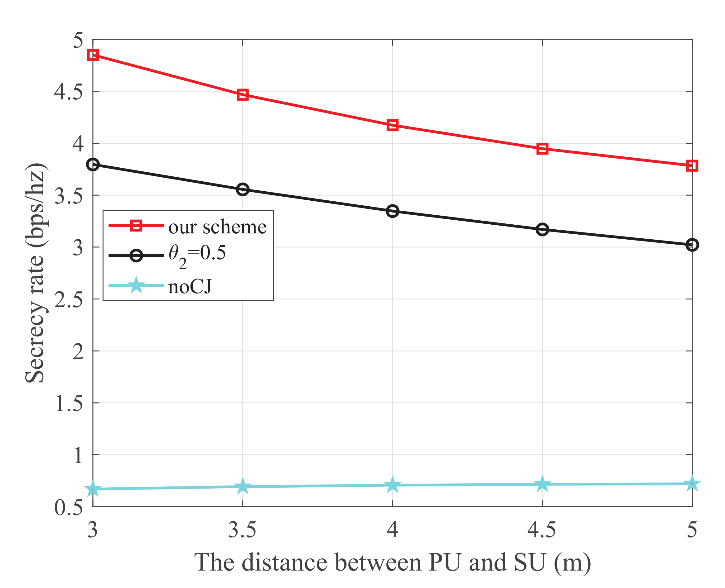
Figure 4 shows the secrecy rate versus the distance between PU and SU, where the energy harvest efficiency
is 0.5, the transmit power at PU is 25 dBm, and the distance from PU to SJ, SU to SR, SU to the eavesdropper, and SJ to the eavesdropper are 4 m, 3 m, 4 m, and 3 m, respectively. It is observed that our scheme is superior to the other two schemes. Additionally, for the scheme using the cooperative jammer, the secrecy rate monotonically decreases with the increase of the distance between PU and SU. This is because SU harvests energy from the PU transmissions. When the distance between PU and SU increases, less energy will be harvested to transmit information, which degrades the main link.
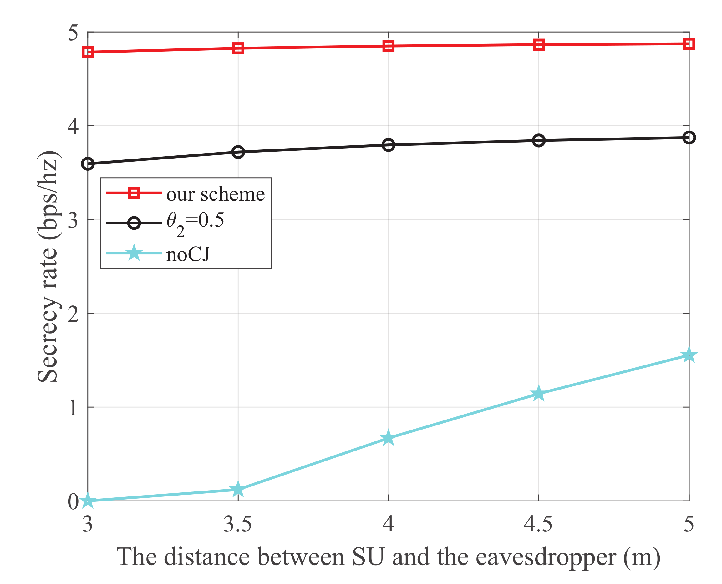
Figure 5 shows the secrecy rate versus the distance between SU and the eavesdropper, where the energy harvest efficiency
is 0.5, the transmit power at PU is 25 dBm, and the distance from PU to SU, PU to SJ, SU to SR, and SJ to the eavesdropper are 3 m, 4 m, 3 m, and 3 m, respectively. It is observed that our scheme is superior to the other two schemes. Moreover, for the noCJ scheme, the secrecy rate monotonically increases with the increase of the distance between SU and the eavesdropper. This is because the wiretap link is degraded as the distance between SU and eavesdropper increases.
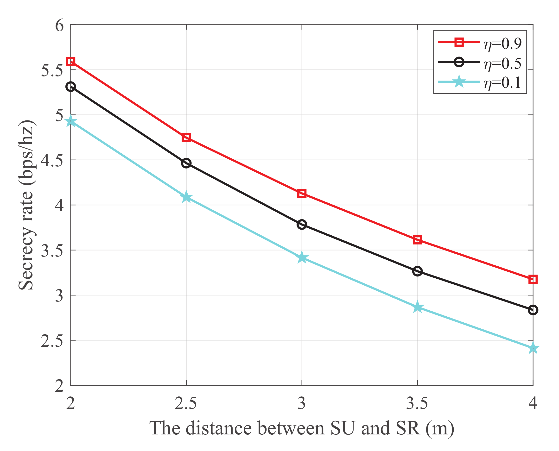
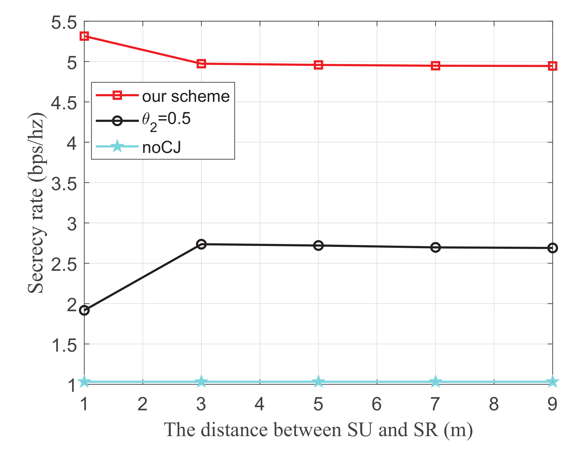
Figure 6 shows the secrecy rate versus the distance between SU and SR with different energy harvest efficiency, where the transmit power at PU is 25 dBm, the distance from PU to SU, PU to SJ, and SJ to the eavesdropper are 2 m, 4 m, and 3 m, respectively. It is observed that the secrecy rate monotonically decreases with the increase of the distance between SU and SR. This is because the main link is degraded as the distance between SU and SR increases. Additionally, it is also observed that the secrecy rate increases with the increase of the energy harvest efficiency. This is because both SU and SJ harvest energy from the PU transmissions. When the energy harvest efficiency
increases, more energy will be captured to transmit information and generate jamming signals, which simultaneously improves the channel quality of the main link and impairs that of the wiretap link, respectively.
6.2. The Secrecy Rate Evaluation for CR Networks with Multiple PUs
Figure 7 shows the secrecy rate versus the transmit power of the PU, where the energy harvest efficiency
is 0.5, and the distance from the 1-th PU to SU, the 2-th PU to SU, the 1-th PU to SJ, the 2-th PU to SJ, SU to SR, SU to the eavesdropper, and SJ to the eavesdropper are 5 m, 3 m, 4 m, 5 m, 3 m, 3 m, and 3 m, respectively.
Figure 7 shows that similar to the CR networks with one PU, the secrecy rate monotonously increases with the transmit power of PUs.
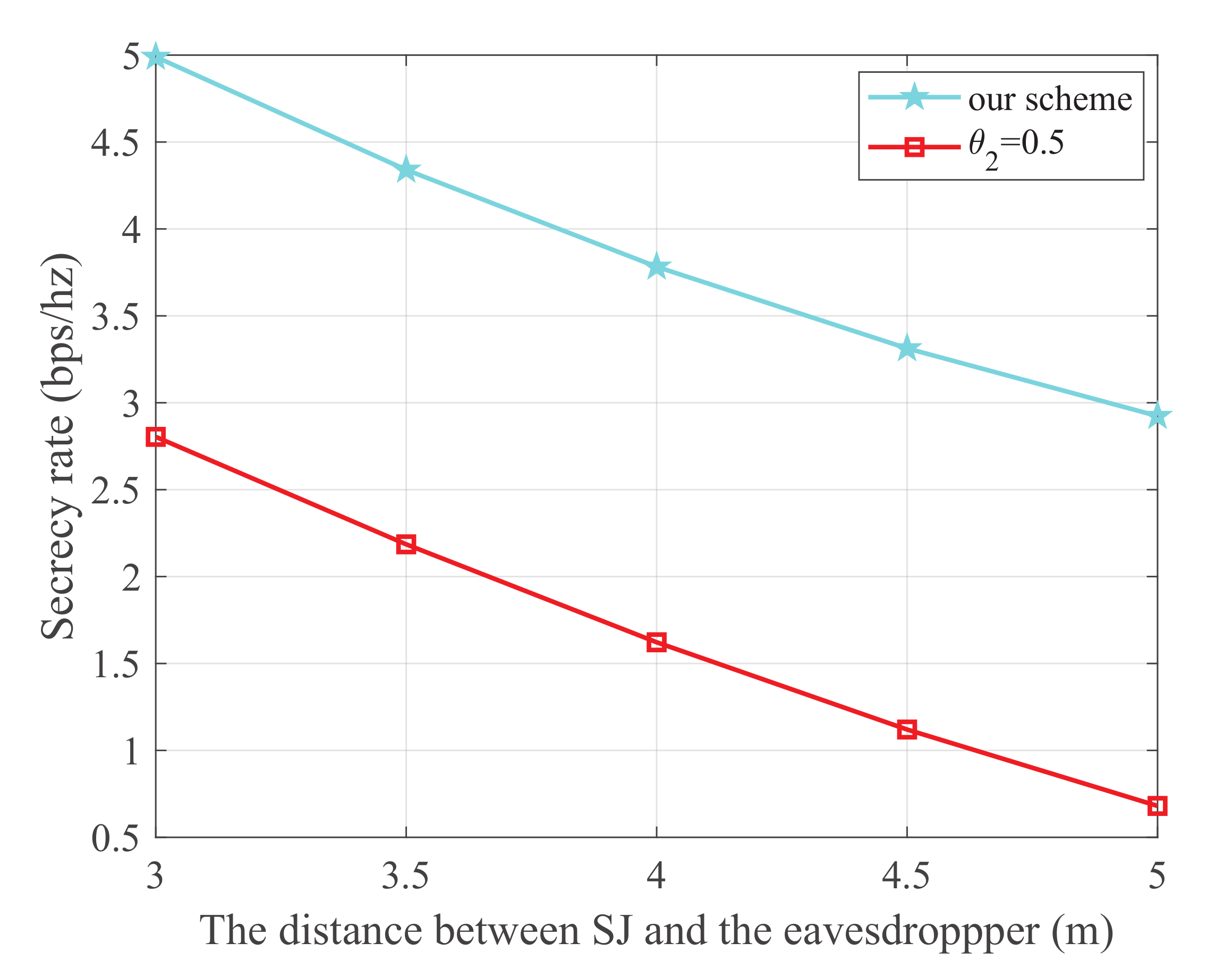
Figure 8 shows the secrecy rate versus the distance between SJ and the eavesdropper, where the energy harvest efficiency
is 0.5, the transmit power of the PU is 25 dBm, and the distance from the 1-th PU to SU, 2-th PU to SU, 1-th PU to SJ, 2-th PU to SJ, SU to SR, SU to the eavesdropper, and SJ to the eavesdropper are 5 m, 3 m, 4 m, 5 m, 3 m, and 3 m, respectively. It is obvious that our scheme is superior to the
scheme. We can also observe that the secrecy rate monotonically decreases with the increase in distance between SJ and the eavesdropper. This is because a smaller distance between SJ and the eavesdropper will further degrade the wiretap link.
Figure 9 shows the secrecy rate versus the distance between SU and SR, where the energy harvest efficiency
is 0.5, the transmit power of the PU is 25 dBm, and the distance from the 1-th PU to SU, the 2-th PU to SU, the 1-th PU to SJ, the 2-th PU to SJ, SU to the eavesdropper, and SJ to the eavesdropper are 3 m, 3 m, 4 m, 5 m, 3 m, and 3 m, respectively. It is observed from our scheme that as the distance between SU and SR increases, the secrecy rate decreases obviously, and then it changes slowly. We can infer that when the distance between SU and SR increases to a certain extent, the distance of which does not cause large fluctuation on secrecy rate.
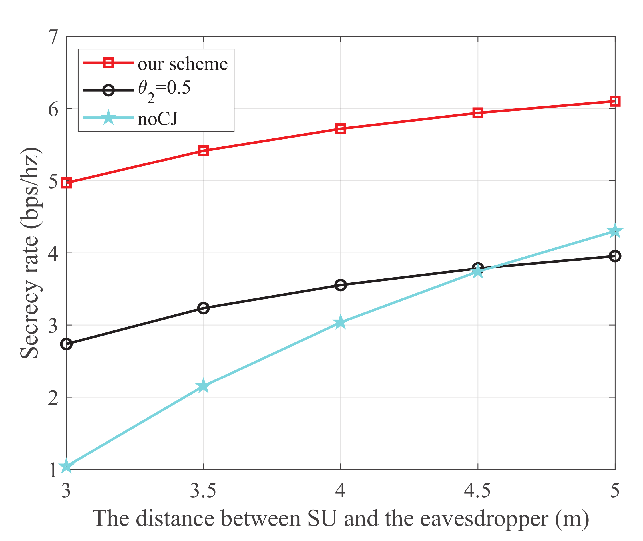
Figure 10 shows the secrecy rate versus the distance between SU and the eavesdropper, where the energy harvest efficiency
is 0.5, the transmit power of each PU is 25 dBm, and the distance from the 1-th PU to SU, the 2t-h PU to SU, the 1-th PU to SJ, the 2-th PU to SJ, SU to SR, and SJ to the eavesdropper are 5 m, 3 m, 4 m, 5 m, 3 m, and 3 m, respectively. We can see that similar conclusions can be drawn as those of
Figure 5.
7. Conclusions
For the underlay CR networks with one PU as well as multiple PUs, this paper studied the PLS of the secondary network while without causing the harmful interference to the primary networks. We introduce a wireless powered cooperative jammer to generate jamming signals to guarantee the information privacy for the secondary network. We first proposed communication schemes for this type of CR networks. Then, we investigated the secrecy rate maximization problems by jointly optimizing the time allocation between the ET phase and IT phase, and the transmit power allocation for SU and SJ. We designed efficient nested form algorithms which are applicable to both two non-convex problems. The numerical results verified that the proposed schemes significantly improve the secrecy performance of the secondary network, as compared to the benchmark schemes.
Author Contributions
This research has been carried out through a concerted effort by six months. Each author’s basic role has been summarizing in following: Conceptualization, S.Z.; methodology, J.S.; software, J.S.; validation, J.S.; investigation, J.S.; writing—original draft preparation, J.S.; writing—review and editing, S.Z.; supervision, K.C.; funding acquisition, K.C. All authors have read and agreed to the published version of the manuscript.
Funding
Zhejiang Provincial Natural Science Foundation of China, Grant/Award Number: LR20F020-003; National Natural Science Foundation of China, Grant/Award Number: 61872322.
Institutional Review Board Statement
Not applicable.
Informed Consent Statement
Not applicable.
Conflicts of Interest
The authors declare no conflict of interest.
References
- Mitola, J.; Maguire, G.Q. Cognitive radio: Making software radios more personal. IEEE Pers. Commun. 1999, 10, 13–18. [Google Scholar] [CrossRef] [Green Version]
- He, Y.; Xue, J.; Ratnarajah, T.; Sellathurai, M.; Khan, F. On the performance of cooperative spectrum sensing in random cognitive radio networks. IEEE Trans. Wirel. Commun. 2018, 12, 881–892. [Google Scholar] [CrossRef] [Green Version]
- Alhamad, R.; Wang, H.; Yao, Y.-D. Cooperative spectrum sensing with random access reporting channels in cognitive radio networks. IEEE Trans. Veh. Technol. 2017, 66, 7249–7261. [Google Scholar] [CrossRef]
- Zheng, K.; Liu, X.; Zhu, Y.; Chi, K.; Liu, K. Total throughput maximization of cooperative cognitive radio networks with energy harvesting. IEEE Trans. Wirel. Commun. 2020, 19, 533–546. [Google Scholar] [CrossRef]
- Zheng, K.; Liu, X.; Liu, X.; Zhu, Y. Hybrid overlay-underlay cognitive radio networks with energy harvesting. IEEE Trans. Commun. 2019, 67, 4669–4682. [Google Scholar] [CrossRef]
- Chi, K.; Zhu, Y.; Li, Y.; Huang, L.; Xia, M.; Xia, M. Minimization of transmission completion time in wireless powered communication networks. IEEE Internet Things J. 2017, 4, 1671–1683. [Google Scholar] [CrossRef]
- Chi, K.; Chen, Z.; Zheng, K.; Zhu, Y.-H.; Liu, J. Energy provision minimization in wireless powered communication networks with network throughput demand: TDMA or NOMA? IEEE Trans. Commun. 2019, 67, 6401–6414. [Google Scholar] [CrossRef]
- Chen, Z.; Chi, K.; Zheng, K.; Li, Y.; Liu, x. Common throughput maximization in wireless powered communication networks with non-orthogonal multiple access. IEEE Trans. Veh. Technol. 2020, 69, 7692–7706. [Google Scholar] [CrossRef]
- Chen, Z.; Chi, K.; Zheng, K.; Dai, G.; Shao, Q. Minimization of transmission completion time in UAV-enabled wireless powered communication networks. IEEE Internet Things J. 2020, 7, 1245–1259. [Google Scholar]
- Luo, Y.; Pu, L.; Lei, L. Impact of varying radio power density on wireless communications of RF energy harvesting systems. IEEE Trans. Commun. 2020, 69, 1960–1974. [Google Scholar] [CrossRef]
- Lyu, B.; Guo, H.; Yang, Z.; Gui, G. Throughput maximization for hybrid backscatter assisted cognitive wireless powered radio networks. IEEE Internet Things J. 2018, 5, 2015–2024. [Google Scholar] [CrossRef]
- Lu, X.; Wang, P.; Niyato, D.; Hossain, E. Dynamic spectrum access in cognitive raido networks with RF energy harvesting. IEEE Wirel. Commun. 2014, 21, 102–110. [Google Scholar] [CrossRef] [Green Version]
- Xu, C.; Zheng, M.; Liang, W.; Yu, H.; Liang, Y. End-to-End throughput maximization for underlay multi-hop cognitive radio networks with RF energy harvesting. IEEE Wirel. Commun. 2017, 16, 3561–3572. [Google Scholar] [CrossRef]
- Bhatt, M.; Boddapati, H.; Prakriya, S. Performance off cluster-based multi-hop underlay networks with energy harvesting nodes. IET Commun. 2020, 14, 1476–1484. [Google Scholar] [CrossRef]
- Pratibha; Li, K.H.; Teh, K.C. Optimal spectrum access and energy supply for cognitive radio systems with opportunistic RF energy harvesting. IEEE Trans. Veh. Technol. 2017, 66, 7114–7122. [Google Scholar] [CrossRef]
- Bae, Y.H.; Baek, J.W. Sensing strategy exploiting channel memory in CR network with RF energy harvesting. IEEE Commun. Lett. 2018, 22, 2539–2542. [Google Scholar] [CrossRef]
- Kishore, R.; Gurugopinath, S.; Sofotasios, P.C. Opportunistic ambient backscatter communication in RF-powered cognitive radio networks. IEEE Trans. Cognit. Commun. Netw. 2019, 5, 413–426. [Google Scholar] [CrossRef] [Green Version]
- Shannon, A.D.; Wyner, T. The wire-tap channel. Bell Syst. Tech. J. 1975, 54, 1355–1387. [Google Scholar] [CrossRef]
- Cumanan, K.; Ding, Z.; Shiarif, B.; Tian, G.Y.; Leung, K.K. Secrecy rate optimizations for a MIMO secrecy channel with a multiple-antenna eavesdropper. IEEE Trans. Veh. Technol. 2014, 63, 1678–1690. [Google Scholar] [CrossRef]
- Yan, P.; Zou, Y.; Ding, X.; Zhu, J. Energy-aware relay selection improves security-reliability tradeoff in energy harvesting cooperative cognitive radio systems. IEEE Trans. Veh. Technol. 2020, 69, 5115–5128. [Google Scholar] [CrossRef]
- Feng, Y.; Yan, S.; Yang, Z.; Yang, N.; Zhu, W. TAS-Based incremental hybrid decode-amplify-forward relaying for physical layer security enhancement. IEEE Trans. Commun. 2017, 65, 3876–3891. [Google Scholar] [CrossRef] [Green Version]
- Li, L.; Petropulu, A.P.; Chen, Z. MIMO secret communications against an active eavesdropper. IEEE Trans. Inf. Forensics Secur. 2017, 12, 2387–2401. [Google Scholar] [CrossRef] [Green Version]
- Liu, J.; Liu, Z.; Zheng, Y.; Ma, J. Cooperative jammer placement for physical layer security enhancement. IEEE Netw. 2016, 30, 56–61. [Google Scholar] [CrossRef]
- Xing, H.; Wong, K.; Chu, Z.; Nallanathan, A. To harvest and jam: A paradigm of self-sustaining friendly jammers for secure AF relaying. IEEE Trans. Signal Process. 2015, 63, 6616–6631. [Google Scholar] [CrossRef] [Green Version]
- Zhang, G.; Xu, J.; Wu, Q.; Cui, M.; Li, X.; Lin, F. Wireless powered cooperative jamming for secure OFDM system. IEEE Trans. Veh. Technol. 2018, 67, 1331–1346. [Google Scholar] [CrossRef] [Green Version]
- Moon, J.; Lee, H.; Song, C.; Lee, I. Secrecy performance optimization for wireless powered communication networks with an energy harvesting jammer. IEEE Trans. Commun. 2017, 65, 764–774. [Google Scholar] [CrossRef]
- Karimi, M.; Sadough, S.M.S.; Torabi, M. Enhanced physical layer security for cognitive radio systems through joint spectrum access and power allocation. IET Commun. 2020, 14, 3135–3142. [Google Scholar] [CrossRef]
- Al-Talabani, A.; Deng, Y.; Nallanthan, A.; Nguyen, H.X. Enhancing secrecy rate in cognitive radio networks via stackelberg game. IEEE Trans. Commun. 2016, 64, 4764–4775. [Google Scholar] [CrossRef] [Green Version]
- Wang, D.; Zhou, F.; Victor, C.M. Primary privacy preserving with joint wireless power and information transfer for cognitive radio networks. IEEE Trans. Cognit. Commun. Netw. 2020, 6, 683–693. [Google Scholar] [CrossRef]
- Liang, Y.; Somekh-Baruch, A.; Poor, H.V.; Shamai, S.; Verdu, S. Capacity of cognitive interference channels with and without secrecy. IEEE Trans. Inf. Theory 2009, 55, 604–619. [Google Scholar] [CrossRef]
- Jiang, Y.; Zou, Y.; Ouyang, J.; Zhu, J. Secrecy energy efficiency optimization for artificial noise aided physical-layer security in OFDM-based cognitive radio networks. IEEE Trans. Inf. Theory 2018, 67, 11858–11872. [Google Scholar] [CrossRef] [Green Version]
| Publisher’s Note: MDPI stays neutral with regard to jurisdictional claims in published maps and institutional affiliations. |
© 2021 by the authors. Licensee MDPI, Basel, Switzerland. This article is an open access article distributed under the terms and conditions of the Creative Commons Attribution (CC BY) license (https://creativecommons.org/licenses/by/4.0/).
