
A Flexible Metamaterial Based Printed Antenna for Wearable Biomedical Applications

Abstract
:1. Introduction
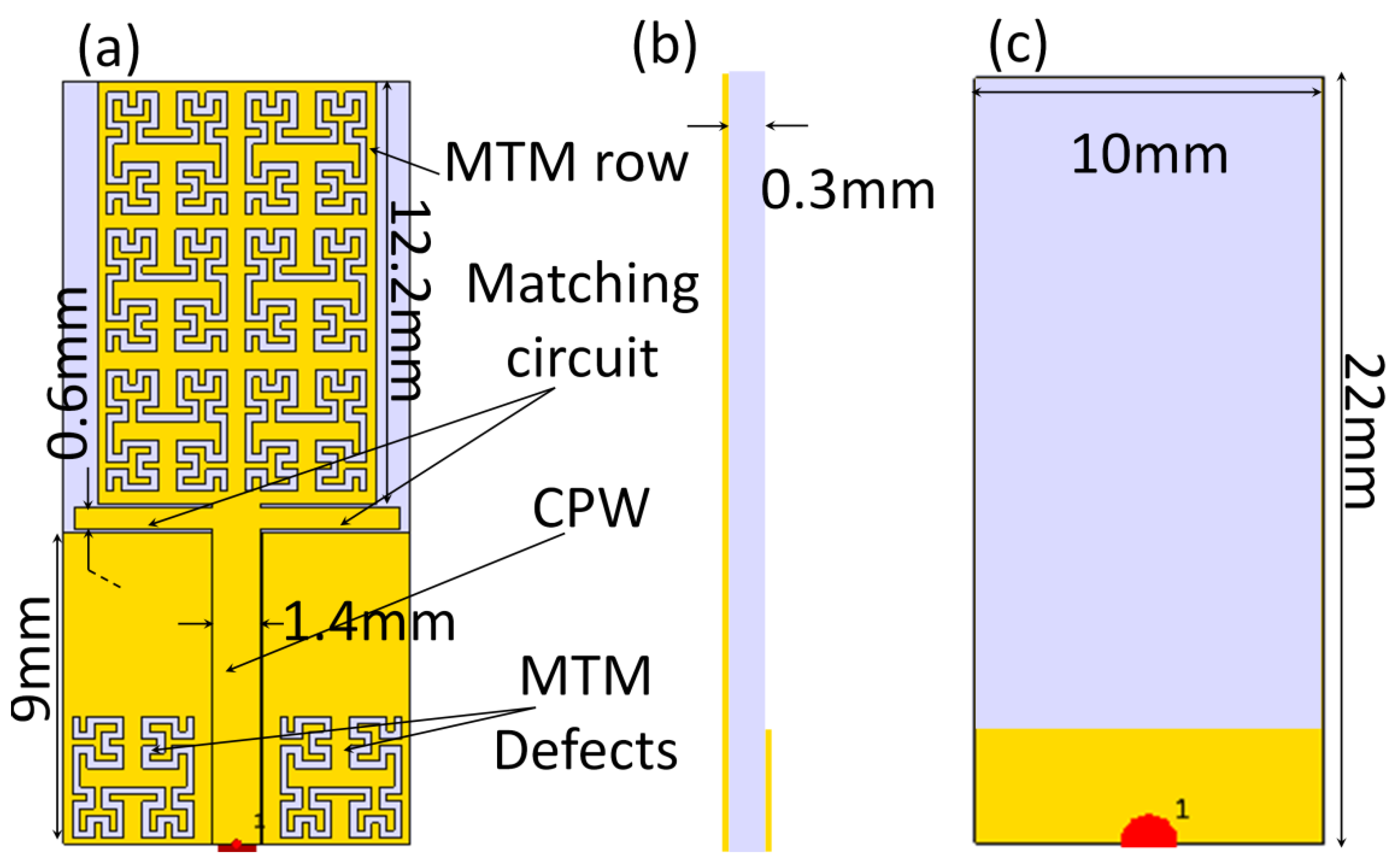
2. Antenna Geometry
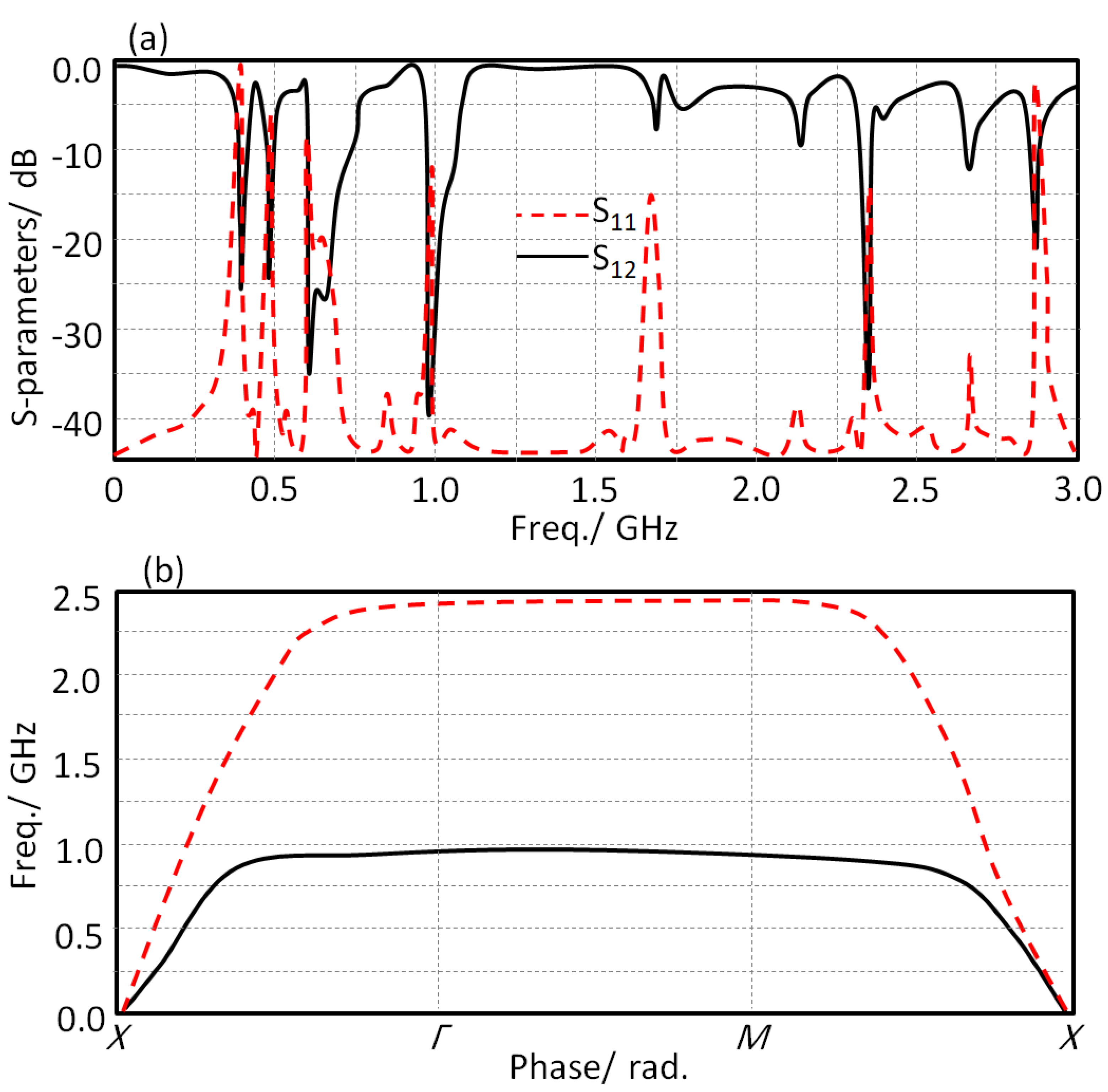
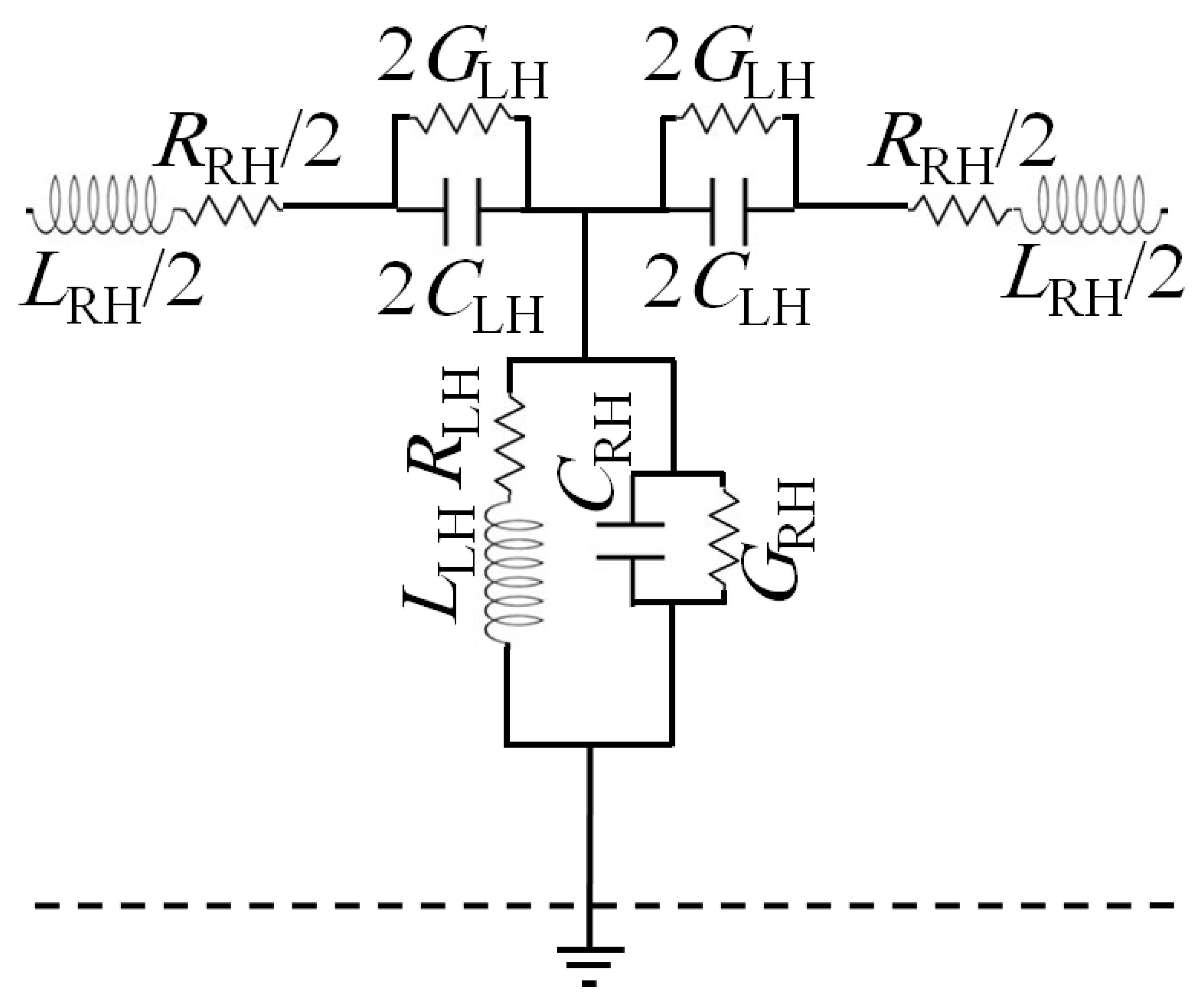
3. MTM Characterizations
4. Design Methodology
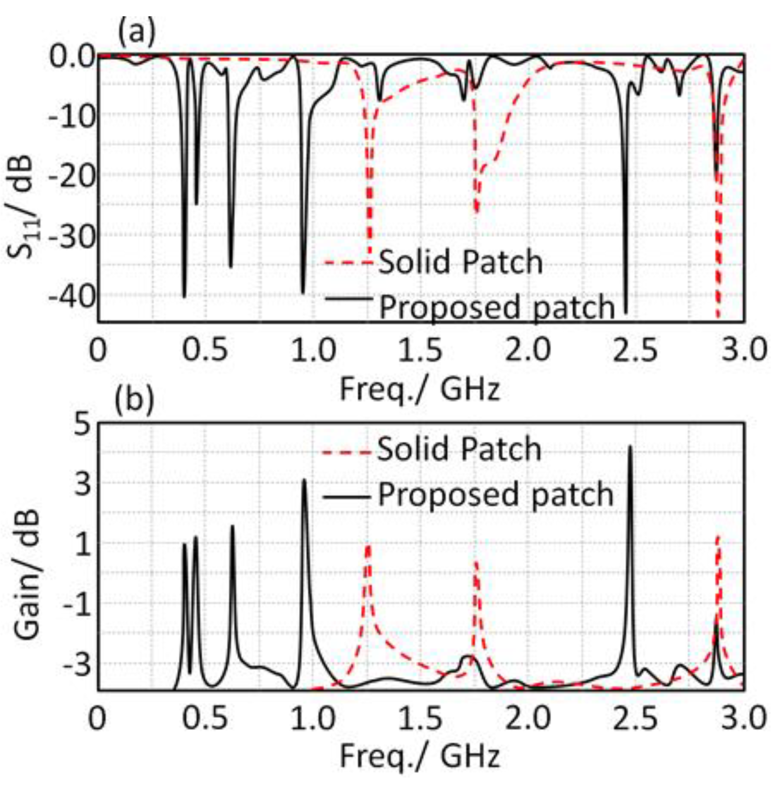
4.1. Patch Design
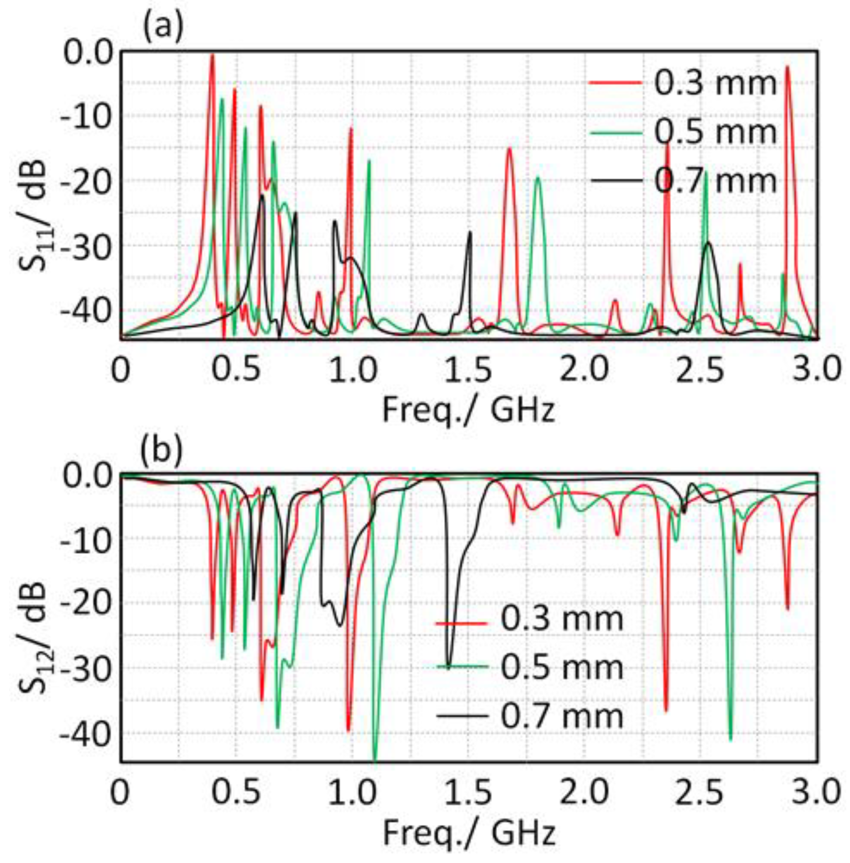
4.2. Matching Circuit
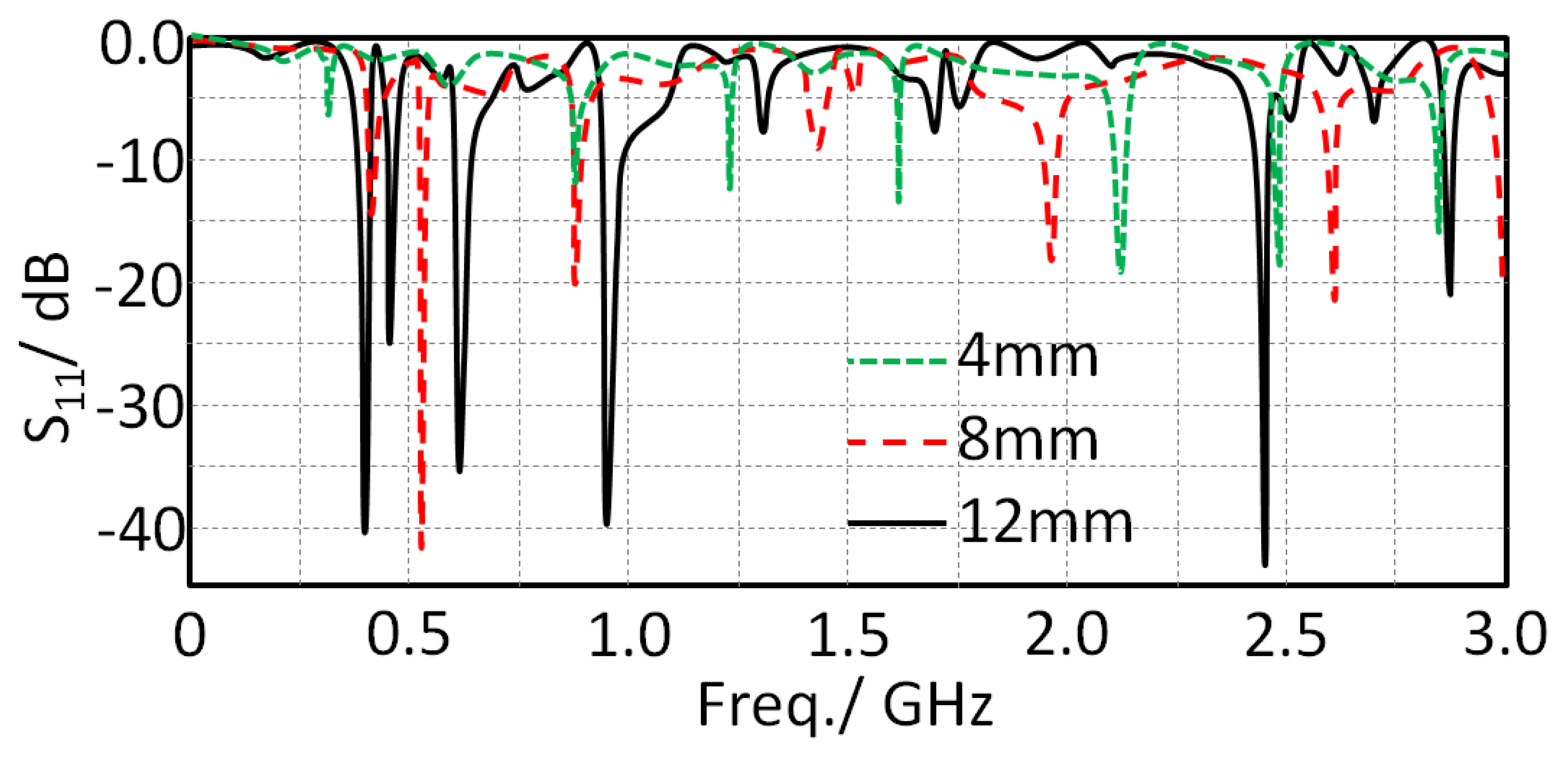
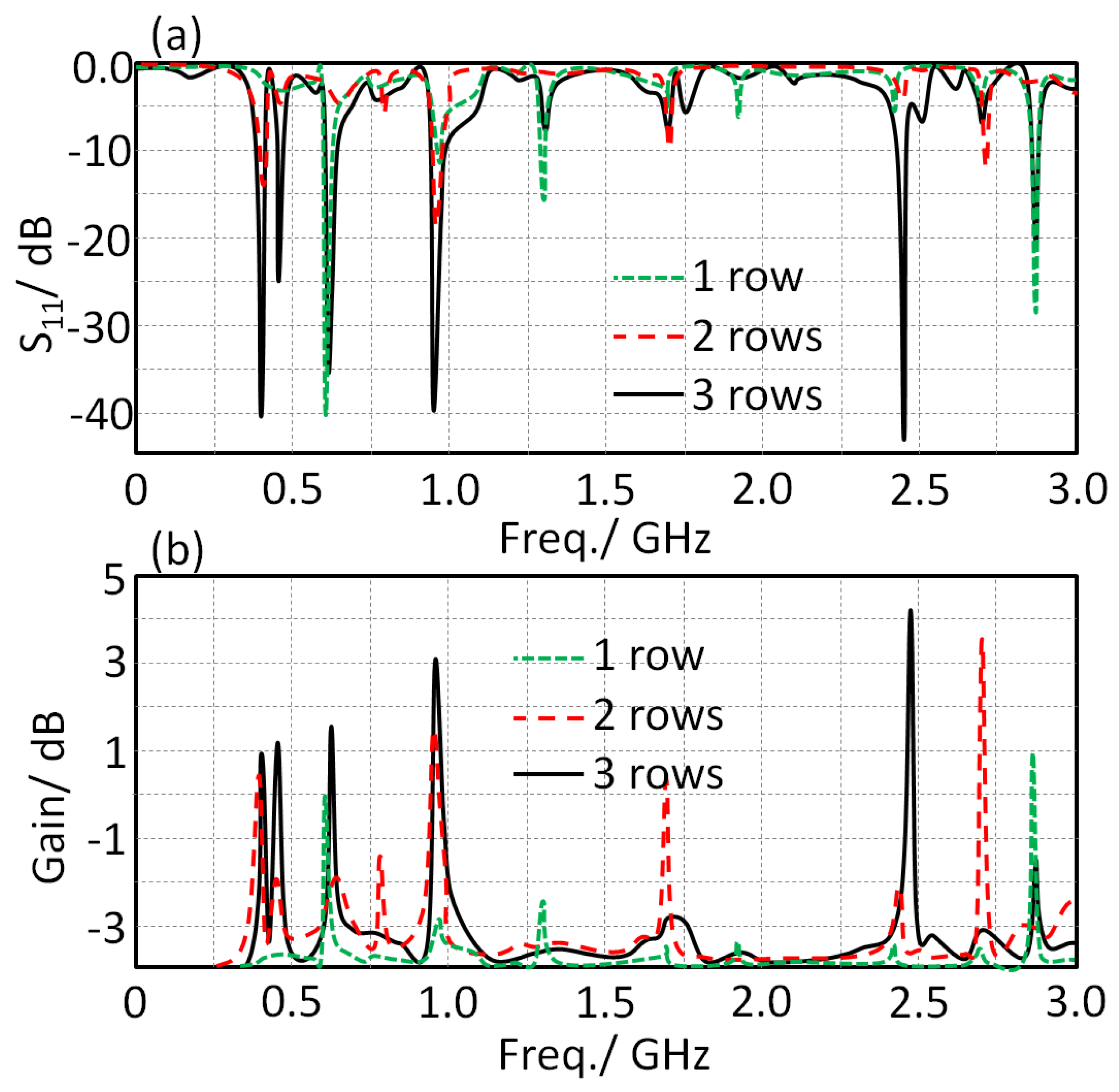
4.3. MTM Effects
5. Bending Effects and Radiation Leakages
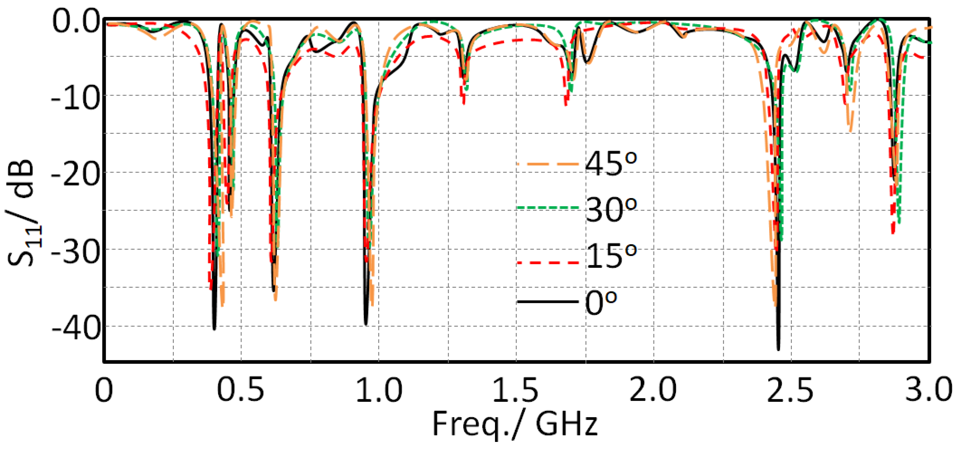
5.1. Bending Effect
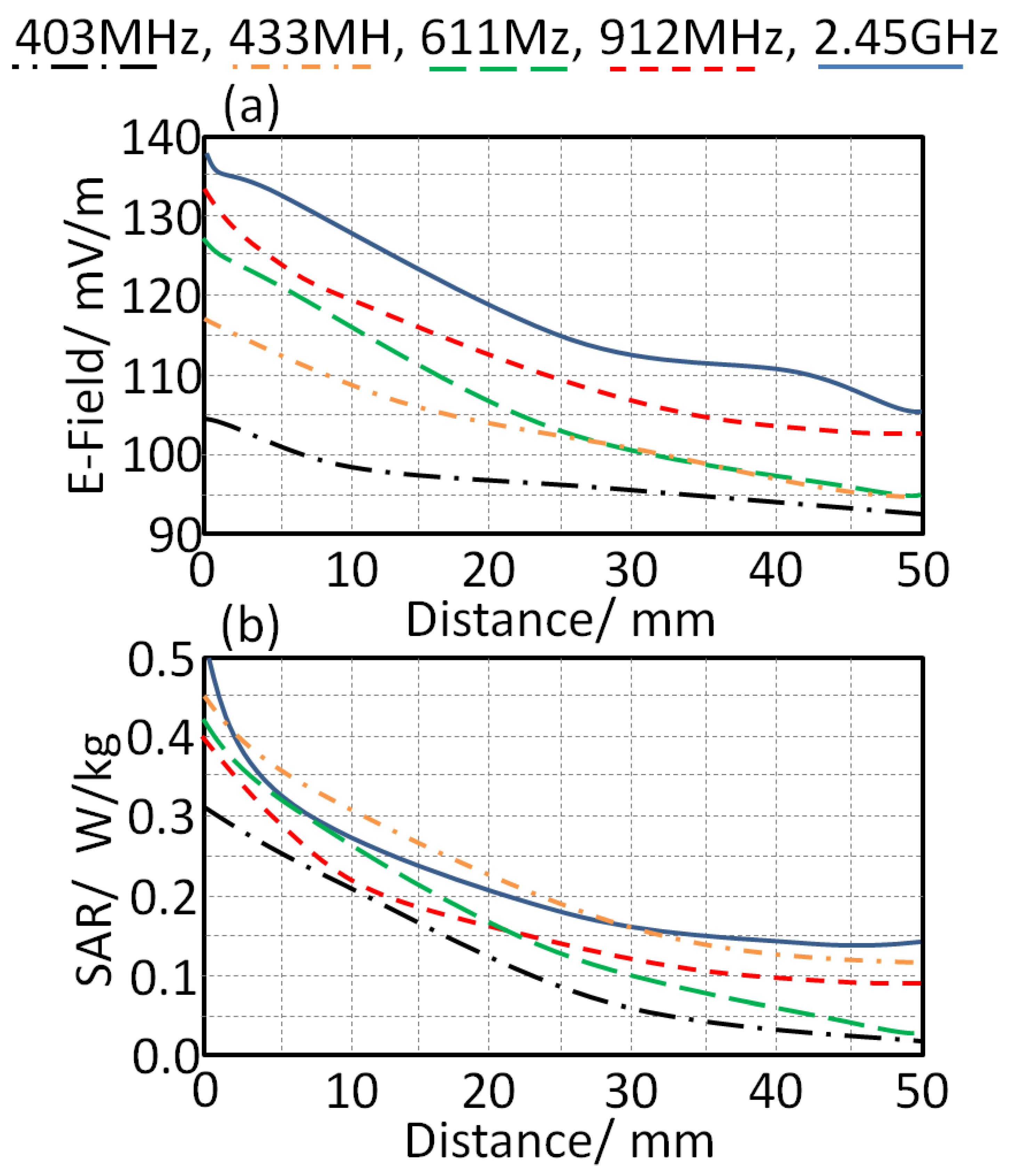
5.2. Radiation Leakage
6. Experimental Results and Discussions
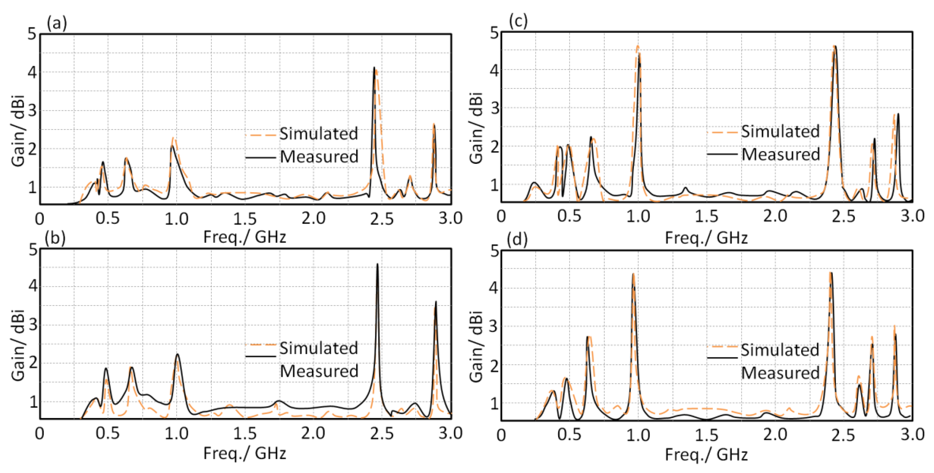
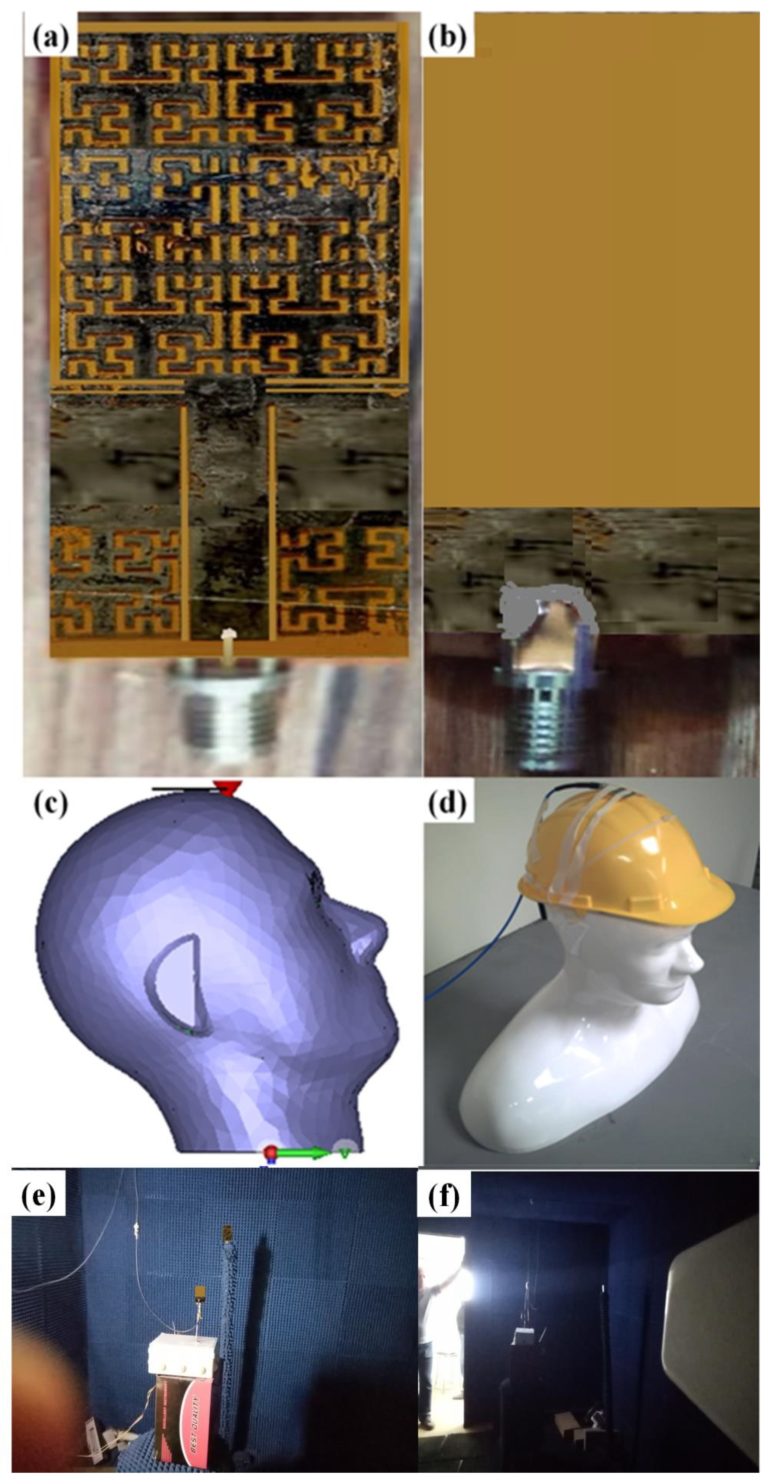
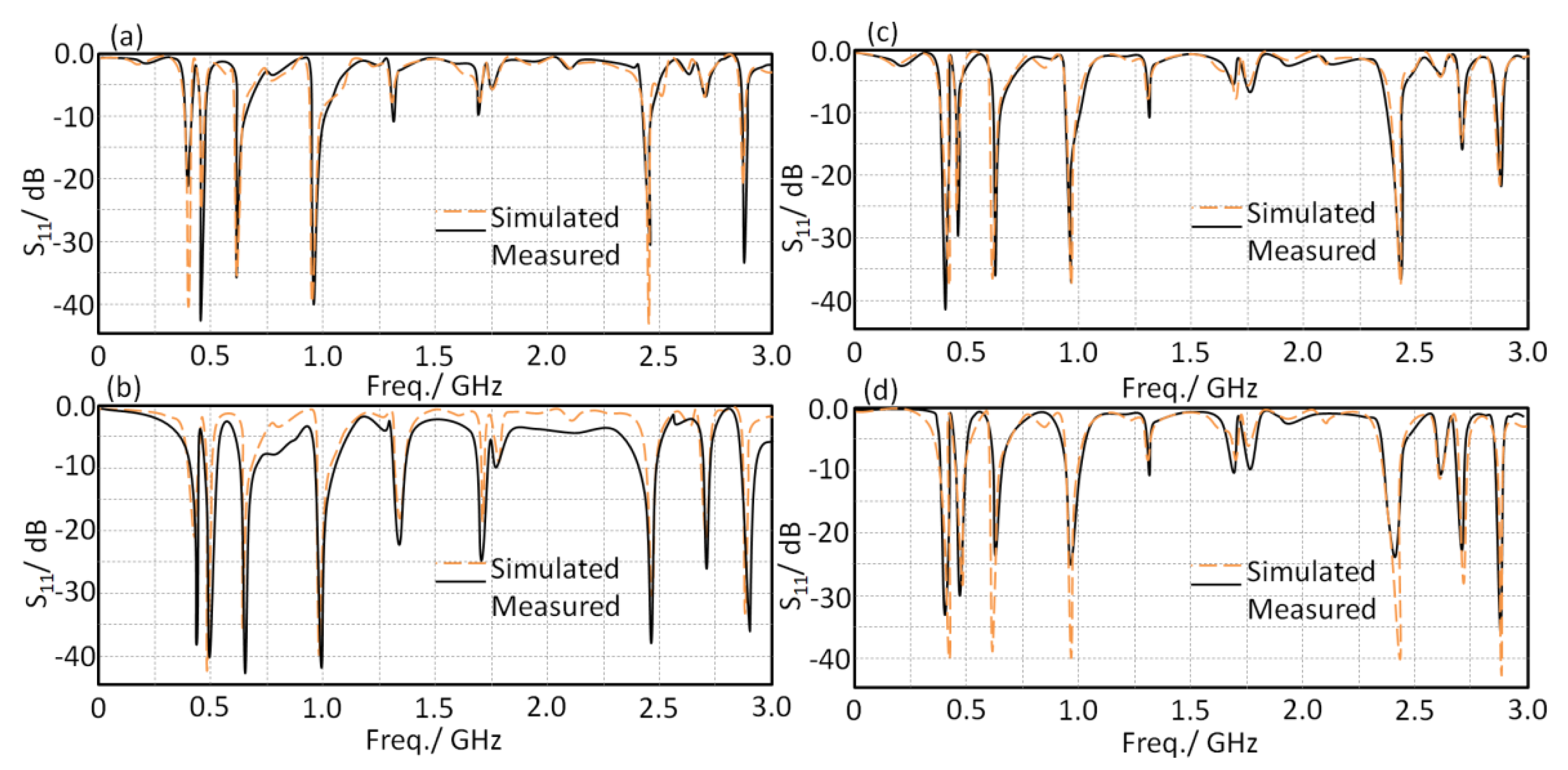
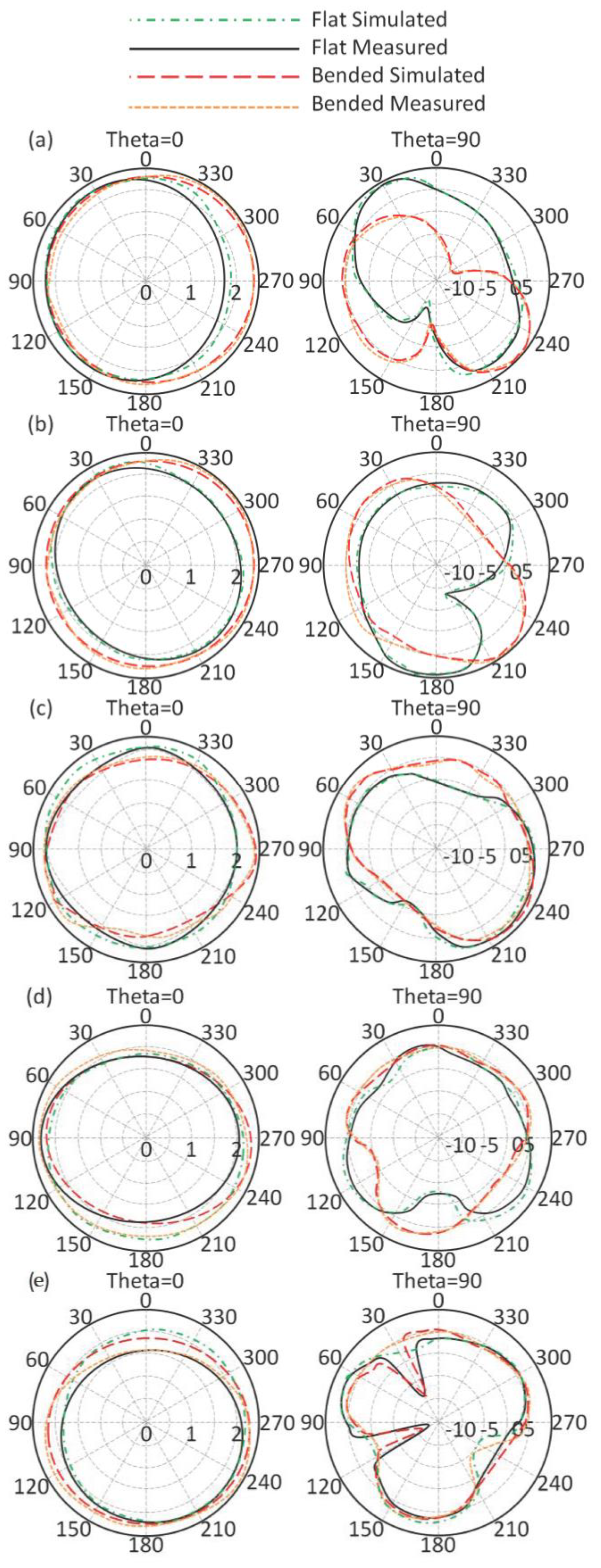
6.1. Antenna Characterizations
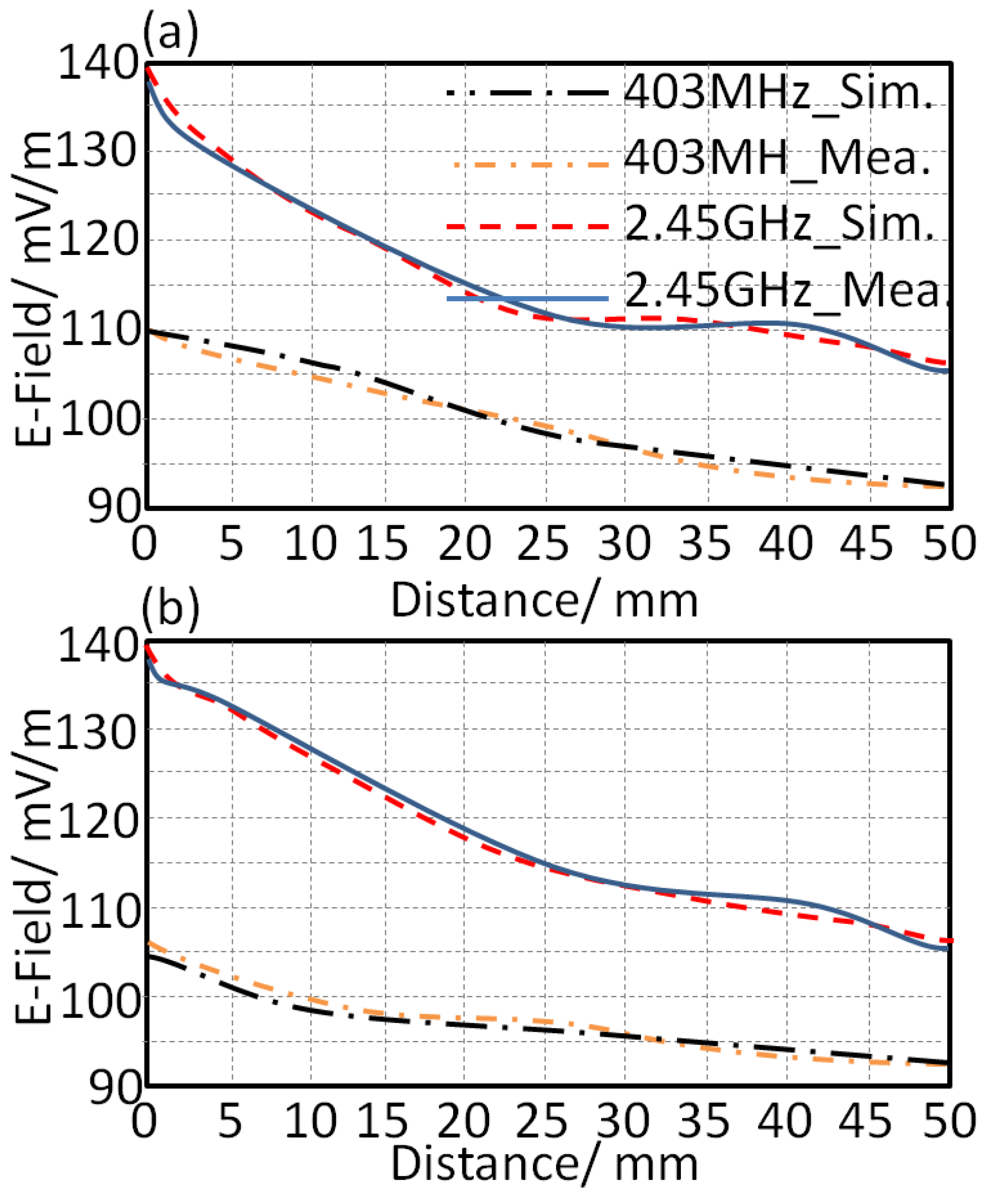
6.2. Radiation Leakage
7. Conclusions
Author Contributions
Funding
Institutional Review Board Statement
Informed Consent Statement
Data Availability Statement
Conflicts of Interest
References
- Abdulsattar, R.K.; Elwi, T.A.; Hassain, Z.A.A. A New Microwave Sensor Based on the Moore Fractal Structure to Detect Water Content in Crude Oil. Sensors 2021, 21, 7143. [Google Scholar] [CrossRef] [PubMed]
- Alaukally, M.N.N.; Elwi, T.A.; Atilla, D.C. Miniaturized flexible metamaterial antenna of circularly polarized high gain-bandwidth product for radio frequency energy harvesting. Int. J. Commun. Syst. 2021, e5024. [Google Scholar] [CrossRef]
- Ali, D.; Elwi, T.; Özbay, S. Metamaterial-based Printed Circuit Antenna for Biomedical Applications. Avrupa Bilim Ve Teknol. Derg. 2021, 26, 12–15. [Google Scholar] [CrossRef]
- Lmako, J. Specific Absorption Rate (SAR) Testing, from a Test Laboratory Perspective; No. 211 7901; Radio Frquency Investigation Ltd.: Basingstoke, UK, 2000. [Google Scholar]
- Kumaran, N.; Arunachalam, K. A Wideband non-Resonant FSS with Finite Number of Unit Cells for Mobile Phone SAR Reduction. In Proceedings of the International Conference on Electromagnetics in Advanced Applications (ICEAA), Cairns, QLD, Australia, 19–23 September 2016; pp. 901–904. [Google Scholar]
- Bhattacharjee, S.; Mitra, M.; Chaudhuri, S.R.B. Improved Matching and SAR Reduction with Little Angular Instable AMC Based Ground Plane. In Proceedings of the International Microwave and RF Conference, New Delhi, India, 5–9 December 2016; pp. 1–4. [Google Scholar]
- Hariharan, V.; Maheshwaran, S.; Selvam, S.; Gunavathi, N. Comparison of Electromagnetic Band Gap (EBG) Structures for Specific Absorption Rate (SAR) Reduction. In Proceedings of the India Conference (INDICON), New Delhi, India, 17–20 December 2015; pp. 1–4. [Google Scholar]
- Han, K.; Swaminathan, M.; Pulugurtha, R.; Sharma, H.; Tummala, R.; Yang, S.; Nair, V. Magneto-dielectric Nanocomposite for Antenna Miniaturization and SAR Reduction. IEEE Antennas Wirel. Propag. Lett. 2015, 5, 72–75. [Google Scholar] [CrossRef]
- Haridim, M. Use of Rod Reflectors for SAR Reduction in Human Head. IEEE Trans. Electromagn. Compat. 2015, 58, 40–46. [Google Scholar] [CrossRef]
- Il Kwak, S.; Sim, D.U.; Kwon, J.H.; Yoon, Y.J. Design of PIFA with Metamaterials for Body-SAR Reduction in Wearable Applications. IEEE Trans. Electromagn. Compat. 2016, 59, 279–300. [Google Scholar]
- Abdel-Mageed, M.; Pelleti, C.; Mittra, R. Penta-Band PIFA for SAR Reduction for Mobile and WLAN Applications Using R-Card. In Proceedings of the IEEE International Symposium on Antennas and Propagation USNC/URSI National Radio Science Meeting, Vancouver, BC, Canada, 19–24 July 2015; pp. 374–375. [Google Scholar]
- Elwi, T.A. Electromagnetic Band Gap Structures based an Ultra Wideband Microstrip Antenna. Microw. Opt. Technol. Lett. 2017, 59, 827–834. [Google Scholar] [CrossRef]
- Elwi, T.A.; Imran, A.I.; Alnaiemy, Y. A Miniaturized Lotus Shaped Microstrip Antenna Loaded with EBG Structures for High Gain-Bandwidth Product Applications. Prog. Electromagn. Res. C 2015, 60, 157–167. [Google Scholar] [CrossRef] [Green Version]
- Elwi, T.A. A Miniaturized Folded Antenna Array for MIMO Applications. Wirel. Pers. Commun. 2008, 98, 1871–1883. [Google Scholar] [CrossRef]
- Imran, A.I.; Elwi, T.A. A Cylindrical Wideband Slotted Patch Antenna Loaded with Frequency Selective Surface for MRI Applications. Eng. Sci. Technol. Int. J. 2017, 20, 990–996. [Google Scholar] [CrossRef]
- Abdulmjeed, A.; Elwi, T.A.; Kurnaz, A.S. Metamaterial Vivaldi Printed Circuit Antenna Based Solar Panel for Self-Powered Wireless Systems. Prog. Electromagn. Res. M 2021, 102, 181–192. [Google Scholar] [CrossRef]
- Imran, A.I.; Elwi, T.A.; Salim, A.A.J. On the Distortionless of UWB Wearable Hilbert-Shaped Metamaterial Antenna for Low Energy Applications. Prog. Electromagn. Res. M 2021, 101, 219–239. [Google Scholar] [CrossRef]
- Al-Dulaimi, Z.; Elwi, T.A.; Atilla, D.C. Design of a Meander Line Monopole Antenna Array Based Hilbert-Shaped Reject Band Structure for MIMO Applications. IETE J. Res. 2020, 1–10. [Google Scholar] [CrossRef]
- Li, J. Computer Aided Modeling and Simulation of Cooling Fan System. In Proceedings of the 2011 International Symposium on Information Engineering and Electronic Commerce (IEEC2011), San José, CA, USA, 5–9 June 2011. [Google Scholar]
- Elwi, T.A.; Al-Rizzo, H.M.; Rucker, D.G.; Khaleel, H.R. Effects of twisting and bending on the performance of a miniaturized truncated sinusoidal printed circuit antenna for wearable biomedical telemetry devices. AEU-Int. J. Electron. Commun. 2010, 13, 1–12. [Google Scholar] [CrossRef]
- CST MWS. 2016. Available online: https://www.cst.com (accessed on 20 November 2021).


| Element | Value |
|---|---|
| RLH | 12.2 Ω |
| RRH | 50 Ω |
| GLH | 0.1 S |
| GRH | 4 S |
| CLH | 1.1 pF |
| CRH | 3.1 pF |
| LLH | 3 nH |
| LRH | 2.2 nH |
| Refs. | Gain | Size | Center Frequency | Substrate Type |
|---|---|---|---|---|
| [1] | −20 dBi | λ/5 | 5 GHz | Fabric |
| [2] | 3 dBi | λ/5 | 1.5 GHz | Solar panel polymer |
| [3] | 4 | 0.12λ | 2.45 GHz | Roger TMM10i |
| [4] | 4.4 | 0.29λ | 5.8 GHz | Unknown |
| [5] | 2.33 | 3.27 mm | 10.1, 24.6 GHz | Rogers RO3010 |
| [6] | 3.7 | 0.06 λ | 2.45 GHz | Meta-cell |
| [7] | 5.1 | 0.13 λ | 2 GHz | Rogers RO4003C |
| [8] | 7.1 | 16 mm | 2.4, 5.8 GHz | Rogers 3210 |
| The proposed work | 1 dBi, 1.24 dBi, 1.48 dBi, 2.05 dBi, and 4.11 dBi | 20 × 10 mm2 | 403 MHz, 433 MH, 611 Mz, 912 MHz, and 2.45 GHz | Polymer |
| References | Human Part | SAR (W/kg) | Centre Frequency (MHz) | Centre Frequency (MHz) |
|---|---|---|---|---|
| [5] | Head tissue | 0.52~0.76 | 900–1800 | 900–1800 |
| [6] | Head tissue | 0.92 | 2400~2500 2500~2690 | 2400~2500 |
| [7] | Head tissue | --- | ||
| [8] | Head tissue | 0.45 | 900 | --- |
| [9] | Head tissue | 0.45 | 850~2200 | 900 |
| [10] | Wrist tissue | 0.32~0.48 | 1960~1980 | 850~2200 |
| [11] | --- | 0.28~0.43 | 930~1900 | 1960~1980 |
| Proposed antenna | Head tissue | 0.32~0.54 | 403, 2450 | 930~1900 |
Publisher’s Note: MDPI stays neutral with regard to jurisdictional claims in published maps and institutional affiliations. |
© 2021 by the authors. Licensee MDPI, Basel, Switzerland. This article is an open access article distributed under the terms and conditions of the Creative Commons Attribution (CC BY) license (https://creativecommons.org/licenses/by/4.0/).
Share and Cite
Al-Adhami, A.; Ercelebi, E. A Flexible Metamaterial Based Printed Antenna for Wearable Biomedical Applications. Sensors 2021, 21, 7960. https://doi.org/10.3390/s21237960
Al-Adhami A, Ercelebi E. A Flexible Metamaterial Based Printed Antenna for Wearable Biomedical Applications. Sensors. 2021; 21(23):7960. https://doi.org/10.3390/s21237960
Chicago/Turabian StyleAl-Adhami, Ammar, and Ergun Ercelebi. 2021. "A Flexible Metamaterial Based Printed Antenna for Wearable Biomedical Applications" Sensors 21, no. 23: 7960. https://doi.org/10.3390/s21237960
APA StyleAl-Adhami, A., & Ercelebi, E. (2021). A Flexible Metamaterial Based Printed Antenna for Wearable Biomedical Applications. Sensors, 21(23), 7960. https://doi.org/10.3390/s21237960