
Three-Dimensional Outdoor Analysis of Single Synthetic Building Structures by an Unmanned Flying Agent Using Monocular Vision


Abstract
:1. Introduction
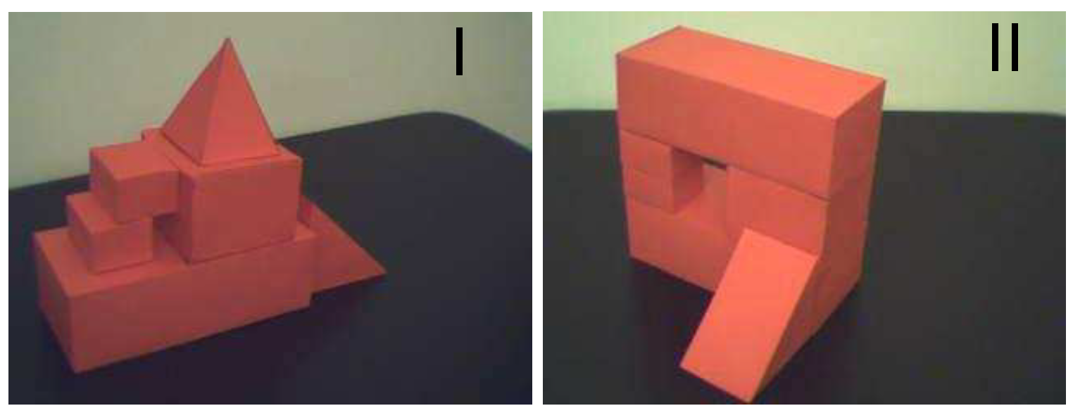
- Developing methods for navigating the robot. Positioning the robot in relation to the object to fly in close proximity. In this publication, it was presented on the example of a flight under a block having the structure of a triumphal arch.
- Color coding of the analyzed scene using the HSV (Hue, Saturation-Value) palette. It was a necessary step to improve image segmentation and extraction of interesting objects from low-quality photos or photos taken under difficult conditions, e.g., shadows, changes in light intensity.
- The vision system is enriched with robot camera image preprocessing.
- The use of a Median Filter [20] with a 7-pixel grid, which results in blurring the image and removing noise.
- Using Gamma correction [21] to darken the image while maintaining contrast. The purpose of this is to avoid overexposure resulting in a color shift in the photo.
- The construction of a 3D model of the scene in nonlaboratory conditions with implementation and integrating it with the other modules on a flying robot, as well as testing in nonlaboratory conditions. The 3D model construction algorithm was described in [18].
1.1. State of the Art
1.2. Problem Formulation
2. Materials and Methods
2.1. Meta-Algorithm
- Robot is provided with a preprocessed image (small map) illustrating some area to be investigated (showing one or more buildings from high altitude). 2D vector representation is calculated along with spatial relations between objects from that input image. Such data structure will be used to search for these objects in the map of overall terrain, obtained in further steps.
- Robot flies above the terrain and takes a photo from an altitude that allows depiction of the desired area (in another implementation, robot could fly or swim lower and take a set of images that would be combined into the complete map of the area).
- From the overall image of the terrain, the robot extracts shapes of the buildings and runs vectorization algorithm [18] to obtain more meaningful 2D representations of objects for further processing. These vectorized objects are stored in the data structure, holding information about the objects’ coordinates in the terrain. The coordinates are derived from the location of each object on the original image. As a result, the vectorized map of the area, called vector map representation, is obtained. The coordinates stored in the map allow the robot to navigate in the terrain to a desired location in the examined scene.
- Robot locates the group of objects from the small map, provided at the beginning, in the vector map representation. To accomplish this, a syntactic algorithm of 2D object recognition is utilized [18]. As a result, using the vector map representation, the robot can move to the desired location where objects for investigation are situated.
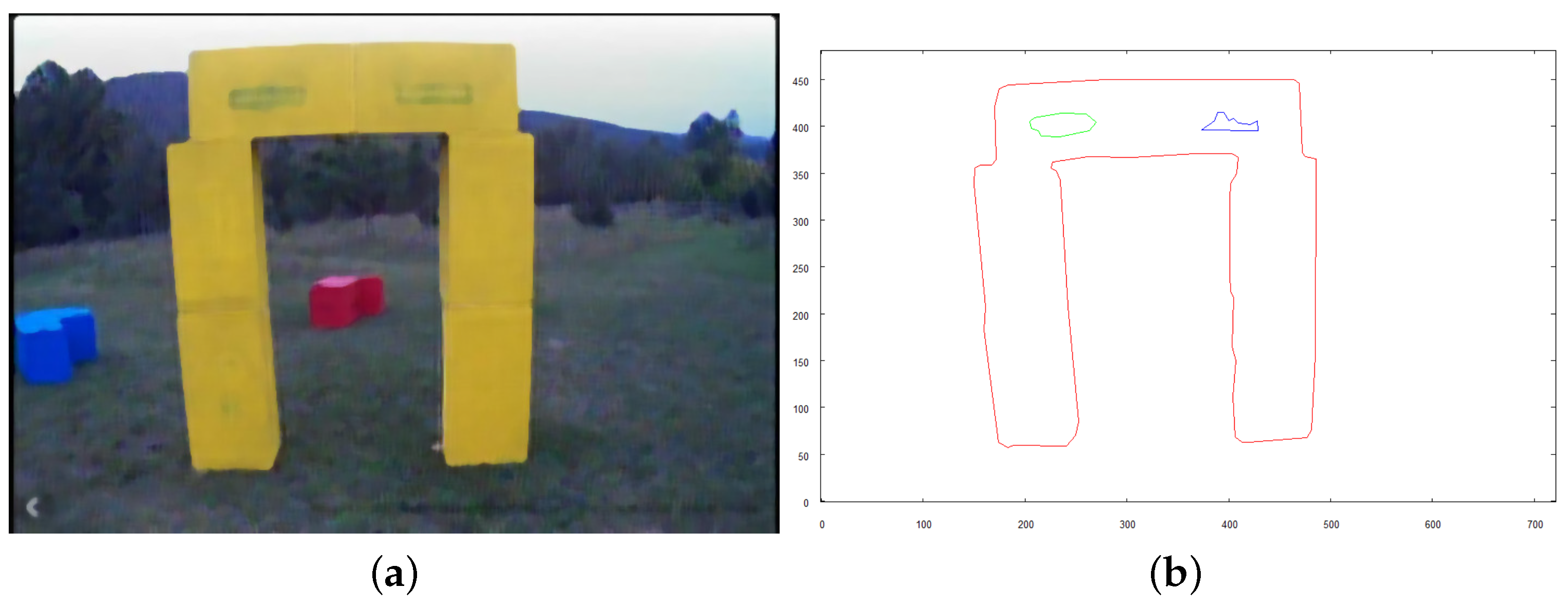
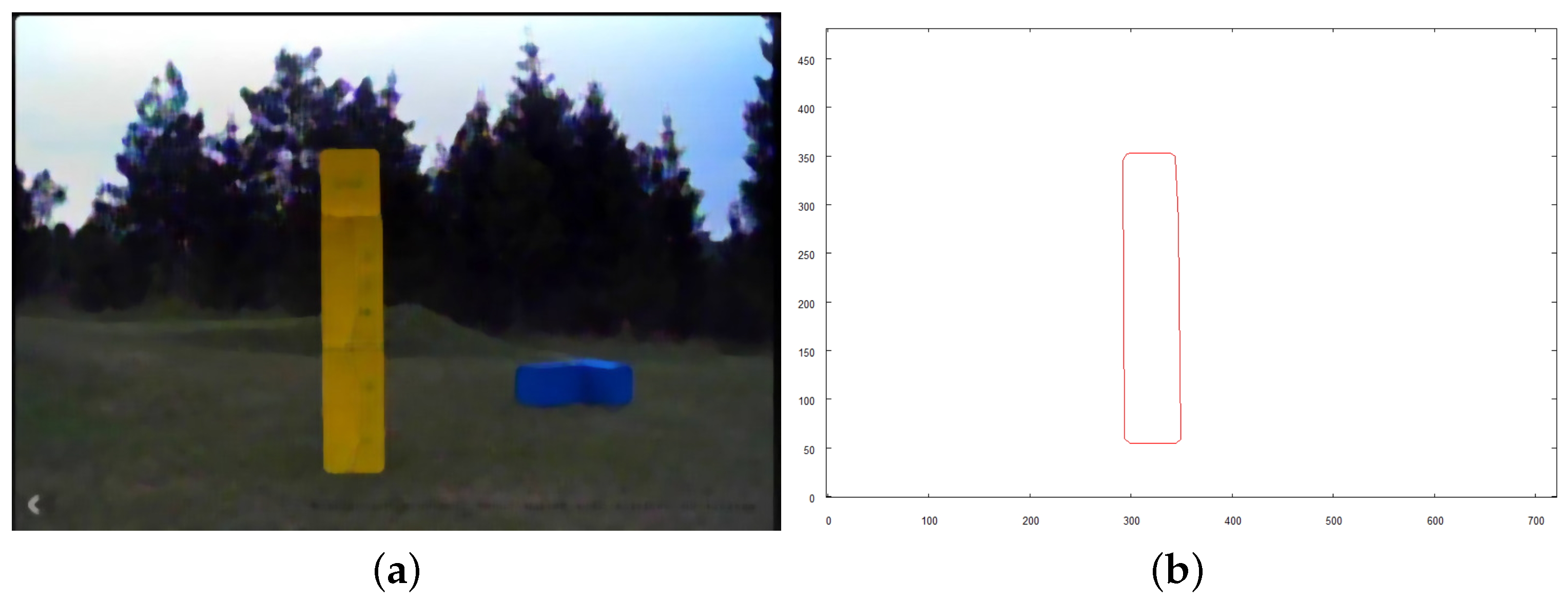
- Vehicle inspects each of the located objects taking a separate set of images for each of them. Such a set consists of one image taken from above the structure, with a camera pointing downwards (from a significantly lower altitude comparing to the moment when robot took the overall image of the area), and the rest of the images are taken horizontally aiming towards particular walls from different sides. Such images are meant to reveal the shape of the building, along with as many features (windows, holes, recesses) as possible.
- Collected images undergoes necessary preprocessing (to reveal objects contours) and vectorization. 2D vector shapes of a building (from different sides) constitute the input for 3D vector model creation.
- 3D models of the examined objects are used to enrich the vector map representation. As a result, this data structure consists of 2D vector data representing overall terrain, with coordinates of the objects observed on the scene, along with 3D vector models of particular buildings “pinned” to their locations. Such data structure is a rich source of information that allows the robot to operate in the area, performing additional tasks close to the structures without collisions.
2.2. Proposed Solution
2.2.1. Prerequisites—Vectorization and Pattern Recognition
2.2.2. Creating 3D Representation
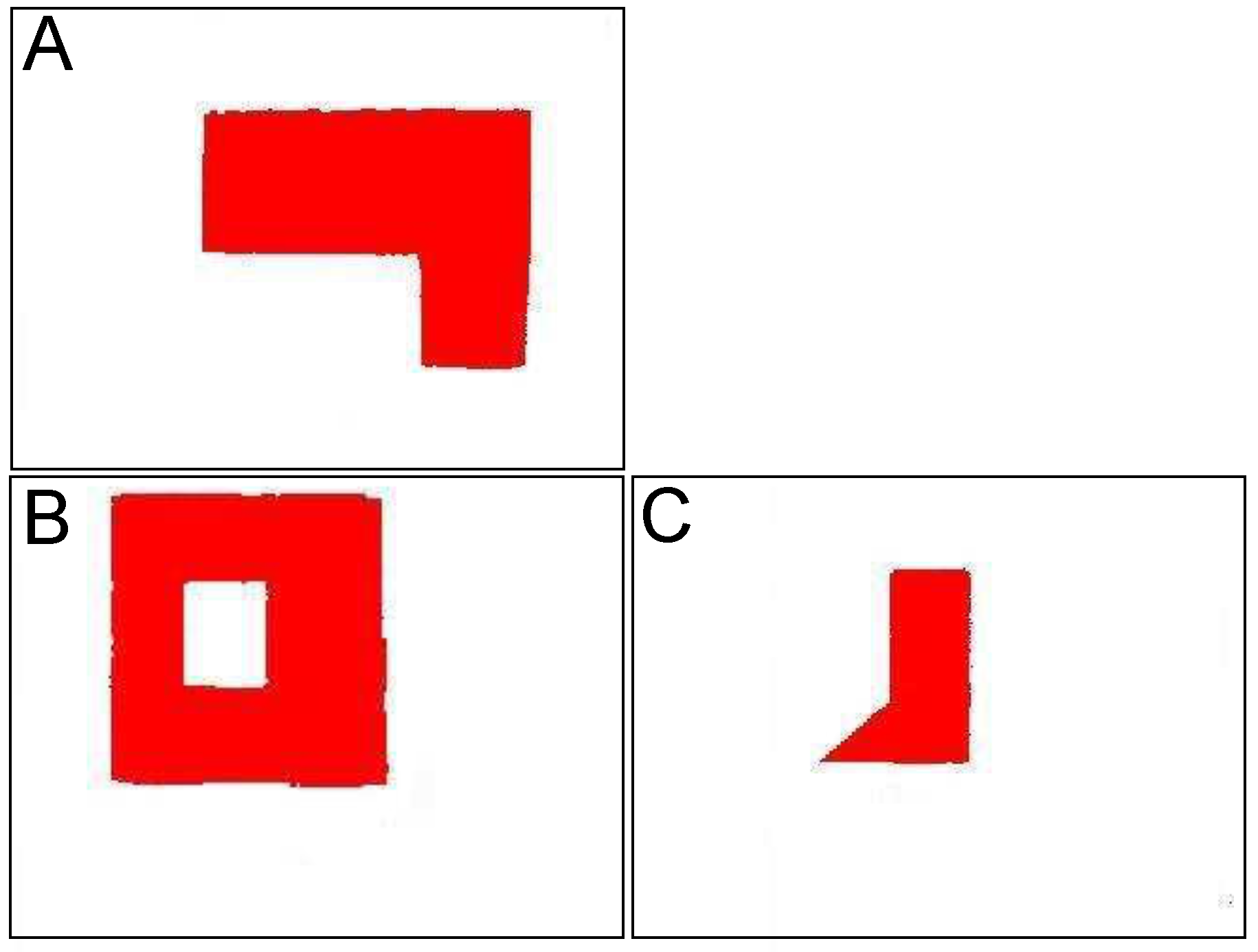
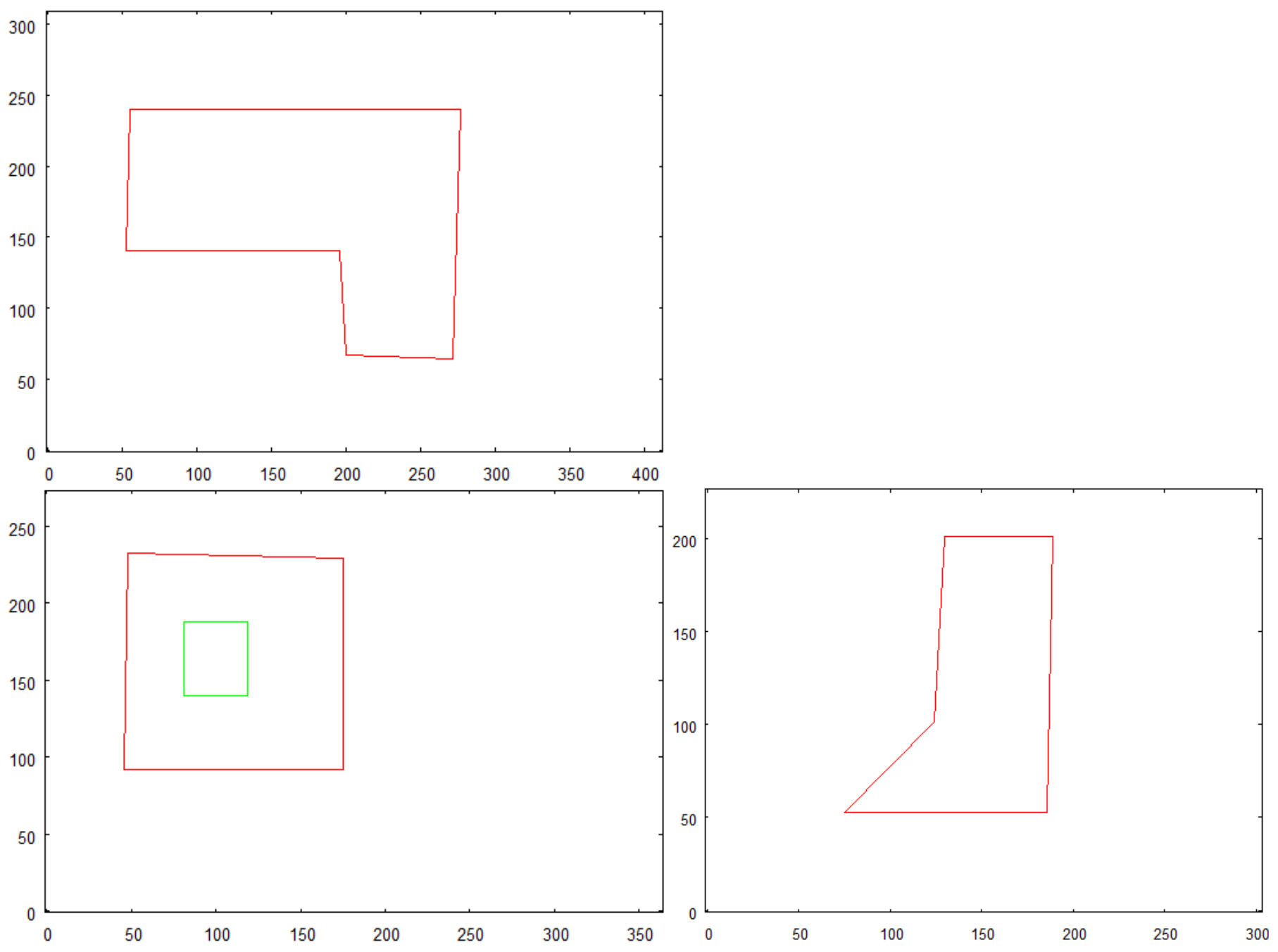
- All pictures, from which vector representation is obtained, have to be taken from the distance from which the overall shape of the building is revealed. Avoidance of the effect of distortion and influence of perspective is the aim of that approach.
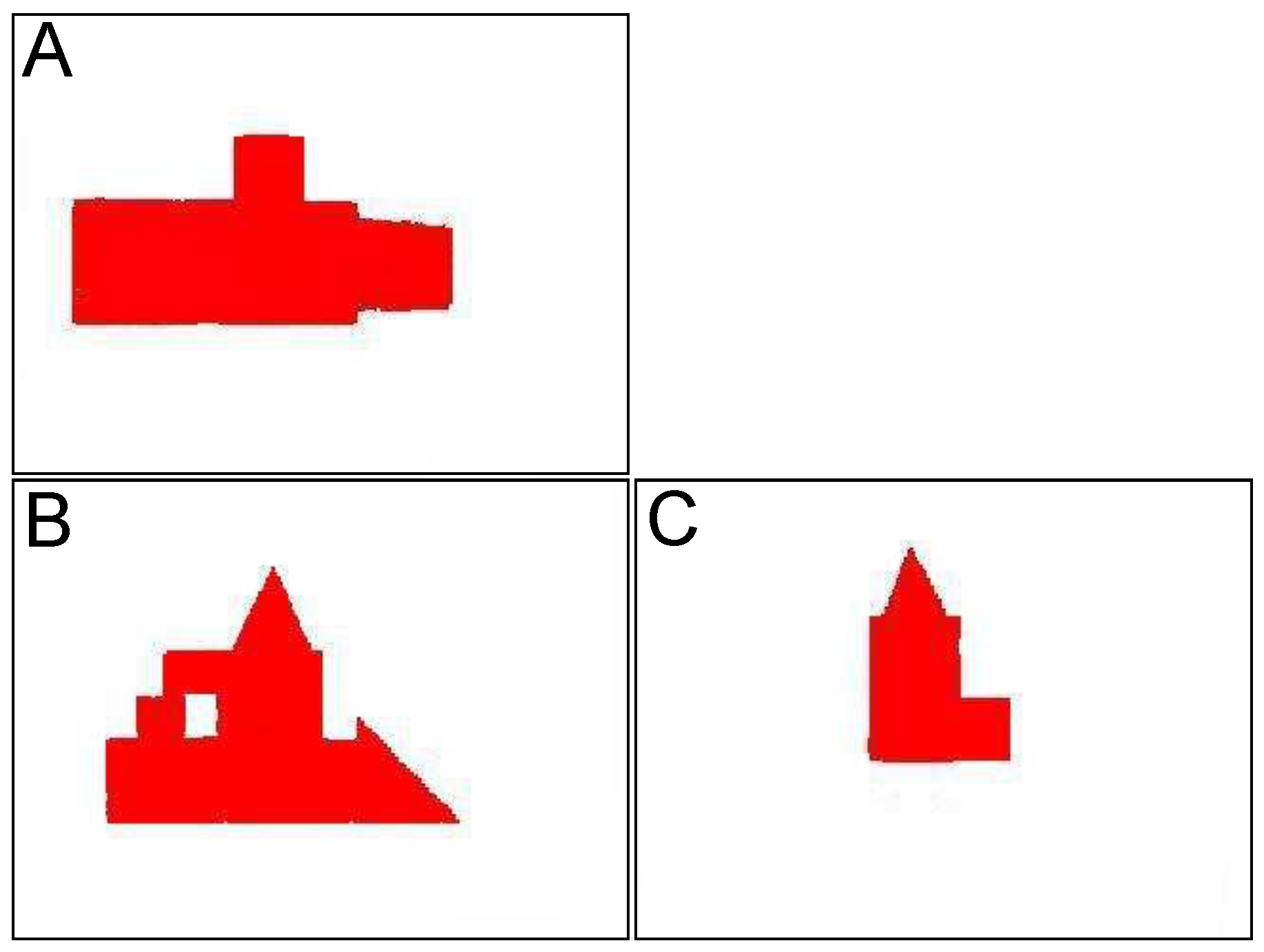
- One picture has to show the top side of the examined building.
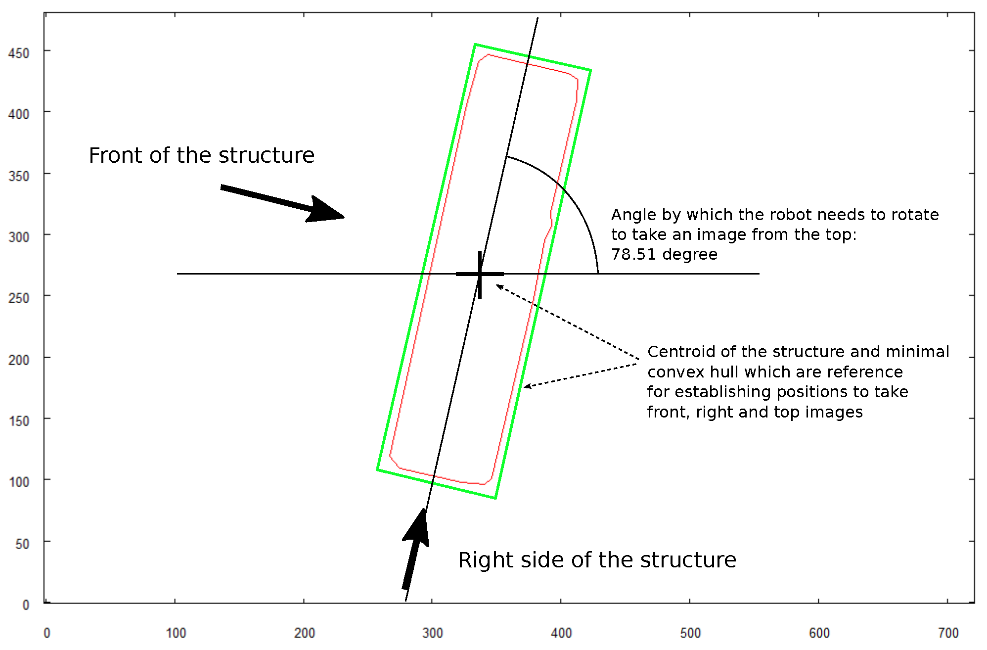
- Two of the pictures have to be taken horizontally from two sides with the angle of between them. One should be taken aiming towards the longest dimension revealed on the picture of the top side. The second one has to be taken aiming at the perpendicular side of the building. In the current application, the right side (looking at the front of the building) of the building is chosen.
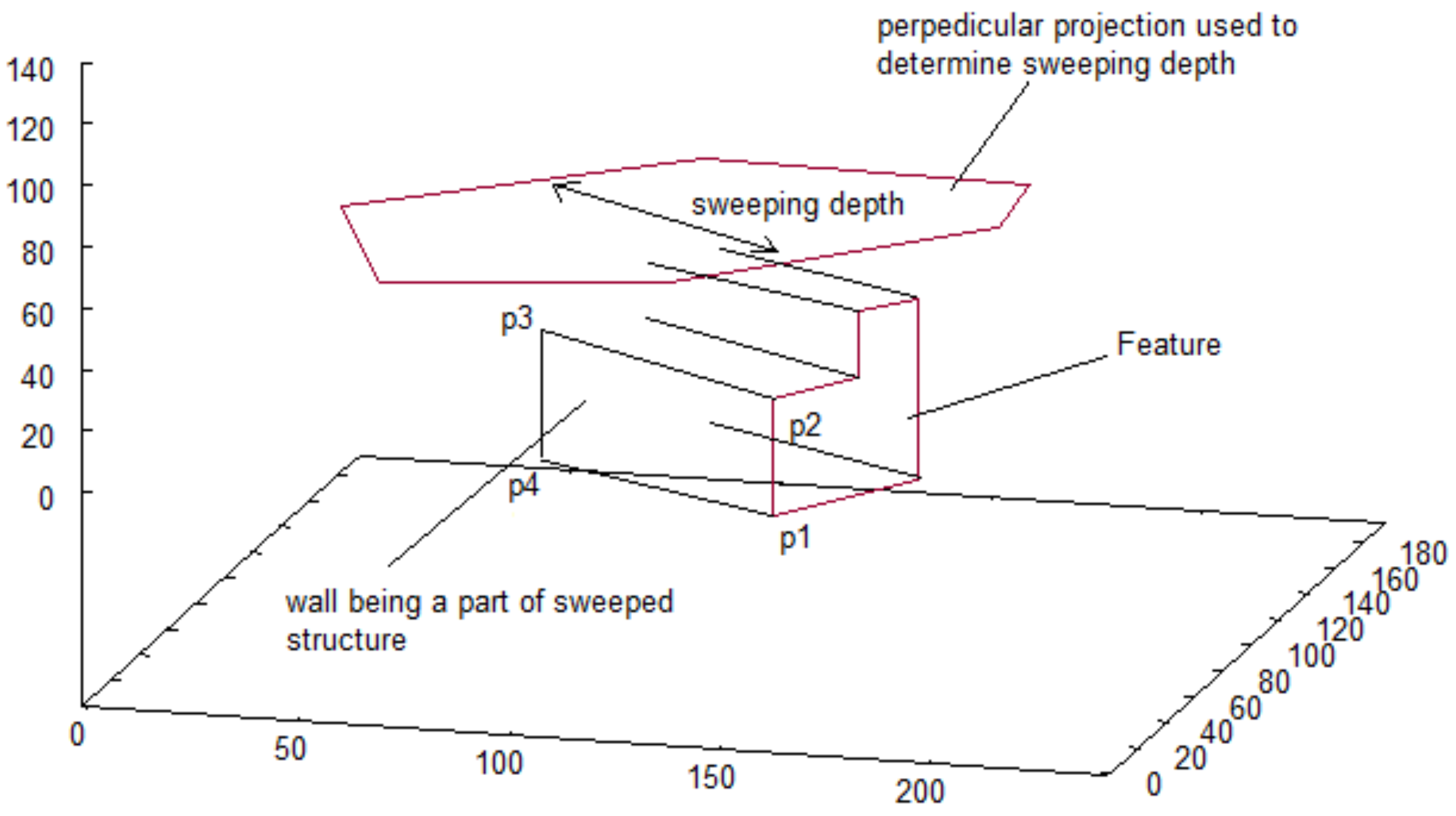
- To reveal the features of the walls (holes), the input set has to include pictures of half of the external side walls of the building ( where n is the number of external walls). To be specific, the building has to be photographed aiming (horizontally) towards half of the sides represented by the convex hull of the top side shape (see Figure 4)
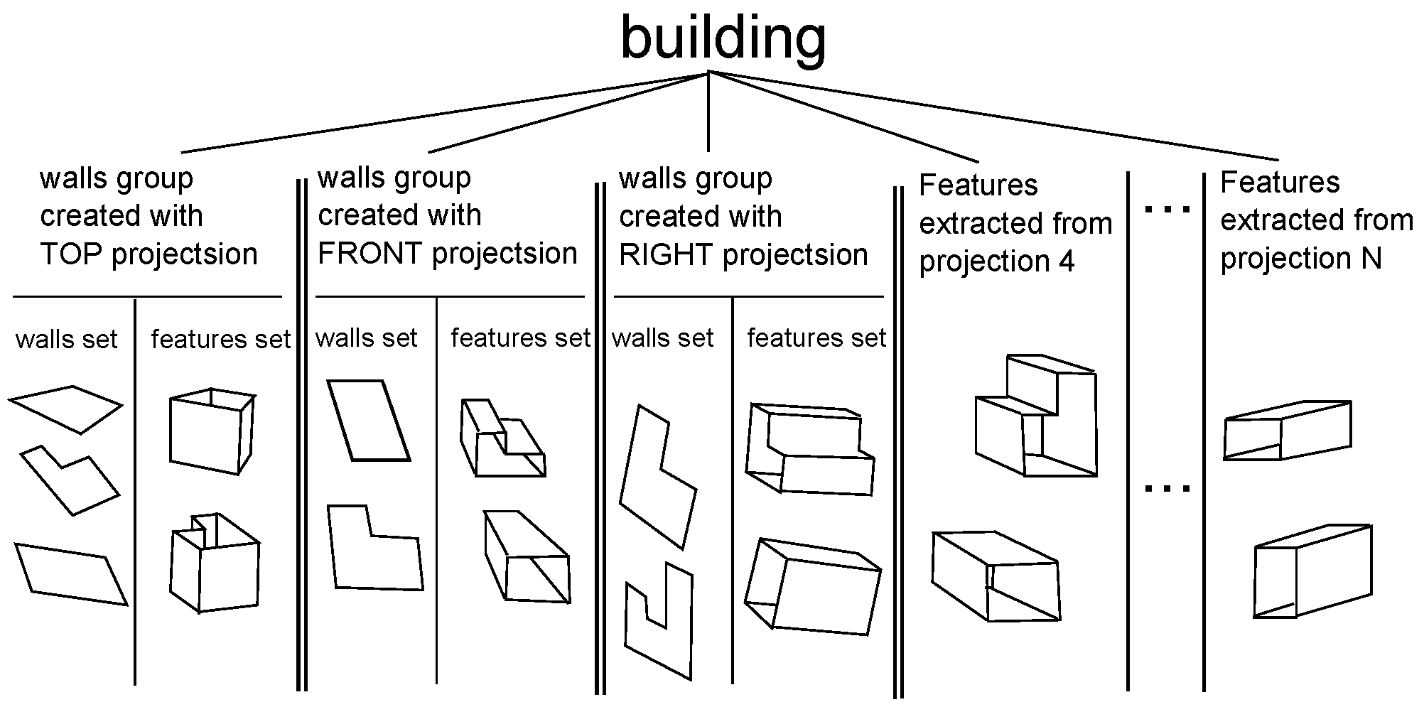
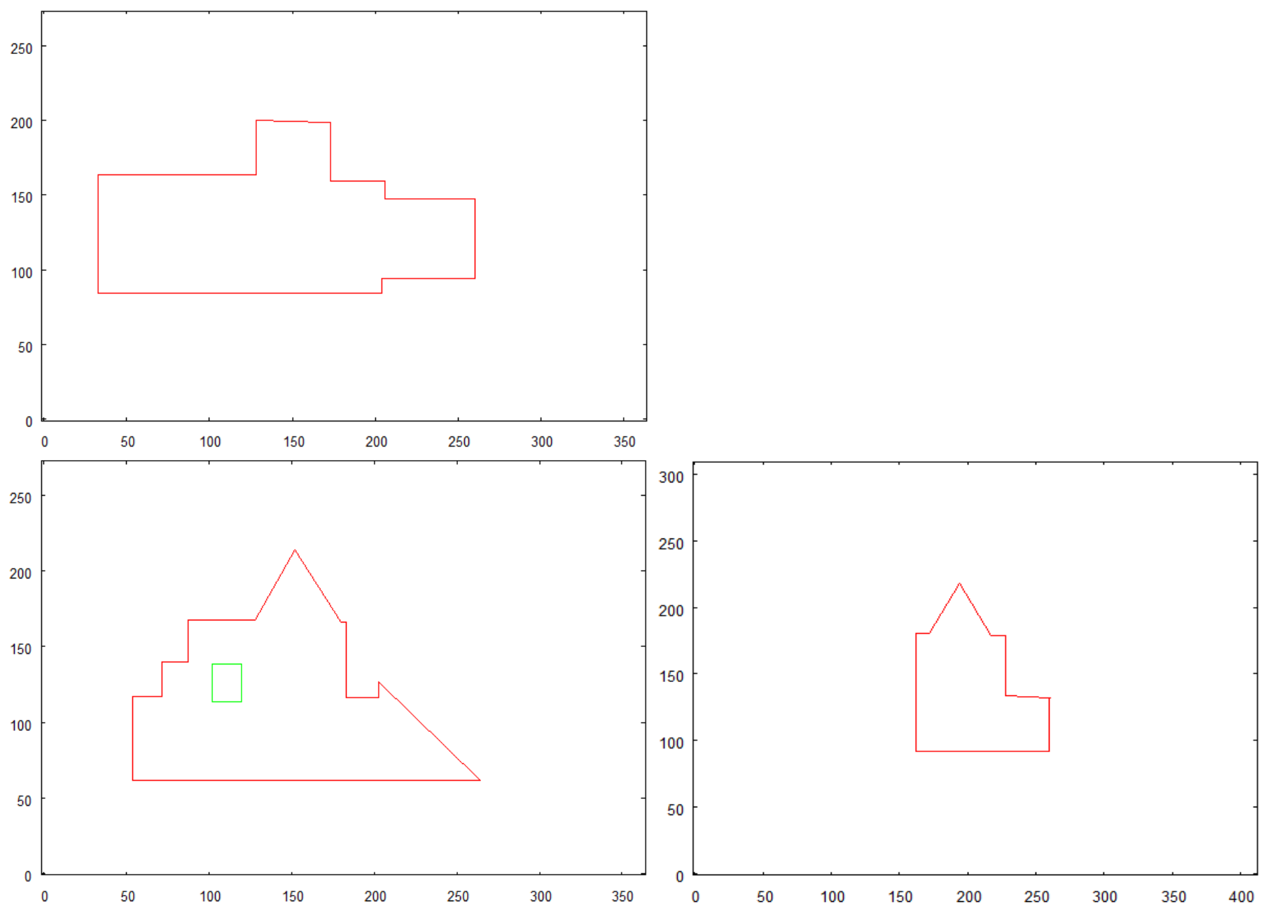
- Creating vector representation of walls with top side picture as a reference.
- Creating a representation of features detected on the top side.
- Creating vector representation of walls with front side picture as a reference.
- Creating a representation of features detected on the front side.
- Creating vector representation of walls with right side picture as a reference.
- Creating a representation of features detected on the right side.
- Creating a representation of features detected on other walls of buildingphotographed horizontally.
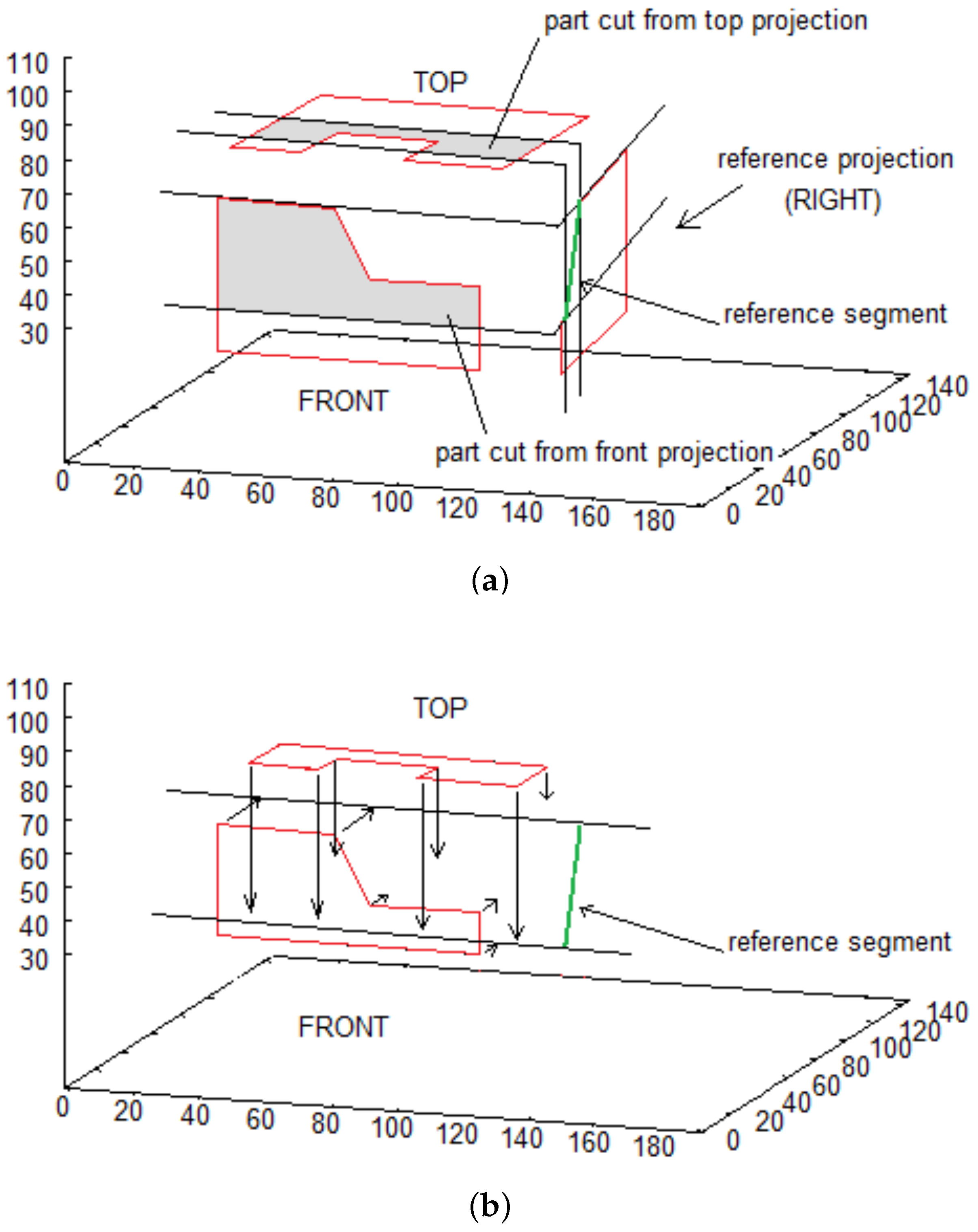
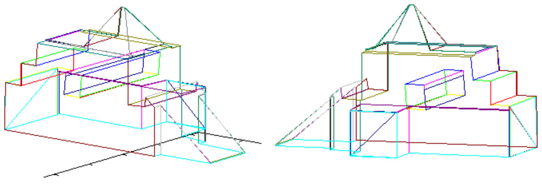
- Get two succeeding point from reference projection: , . Such pair is called reference segment
- Reference segment is used to cut parts from two other projections and translate obtained sequences of points as shown in Figure 5a,b,
- Obtained walls lie on the same plane, perpendicular to reference wall (right in presented example), whose inclination is defined by the reference segment. Each partial wall is represented similarly to original walls—by sequence of points on its border.
- Final step consists in calculating common part of walls (see Figure 5c)
2.3. 3D Vector Map Representation
3. Results
3.1. Construction of the Enriched 3D Model of the Scene
- Input data with the picture of building (group of buildings) consists of preprocessed bitmap showing structure (structures) from above on a white surface. This works as a small map for the algorithm
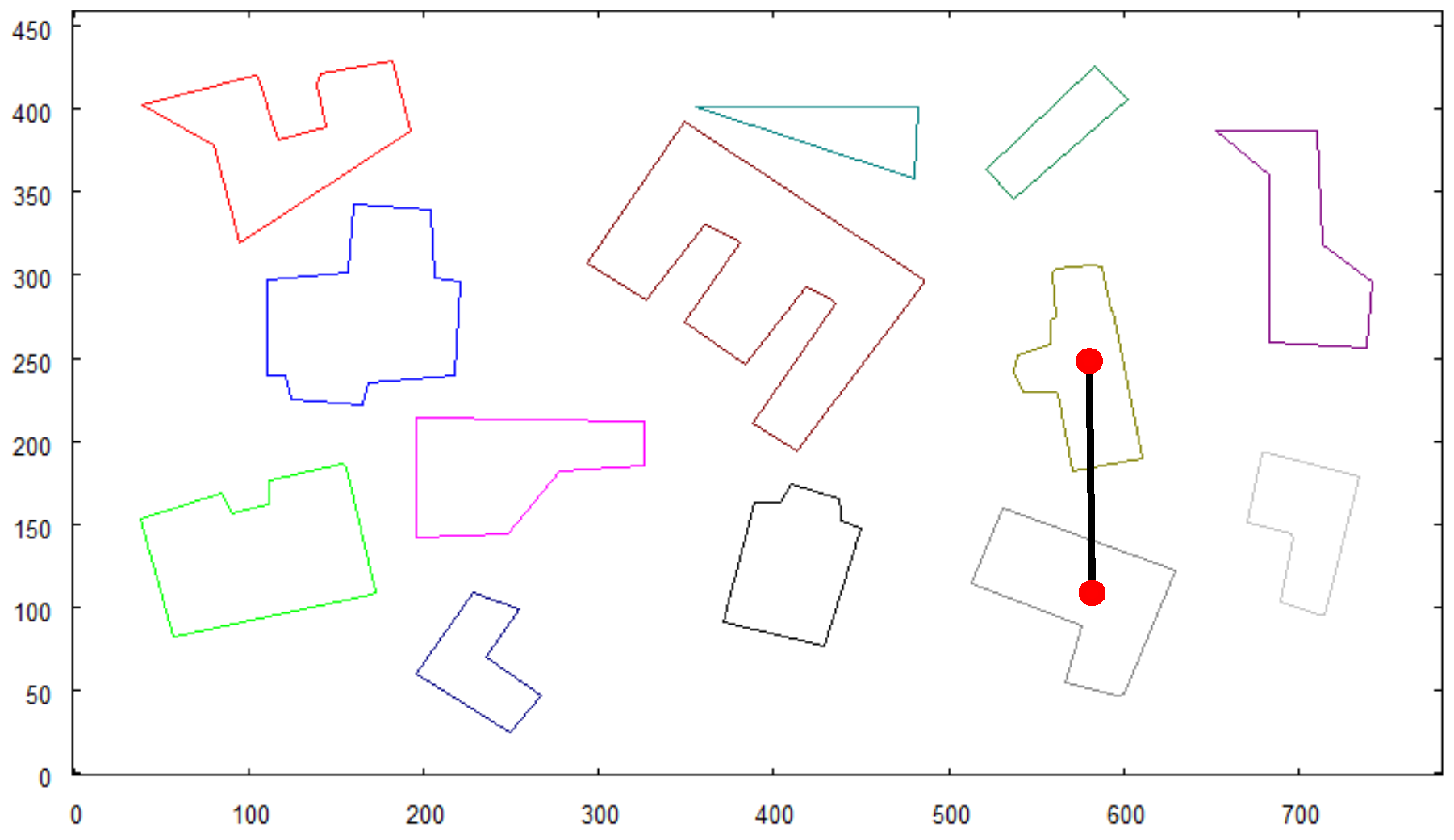
- In place of taking a photo of the overall area from height, as it would take place when testing with the robot, another preprocessed photo is provided to the algorithm as input data. It consists of a bitmap showing a large group of objects on a white background, which represents buildings’ shapes observed from high altitude (see Figure 7).
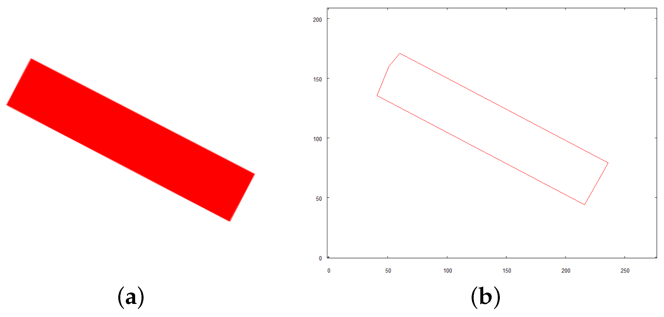
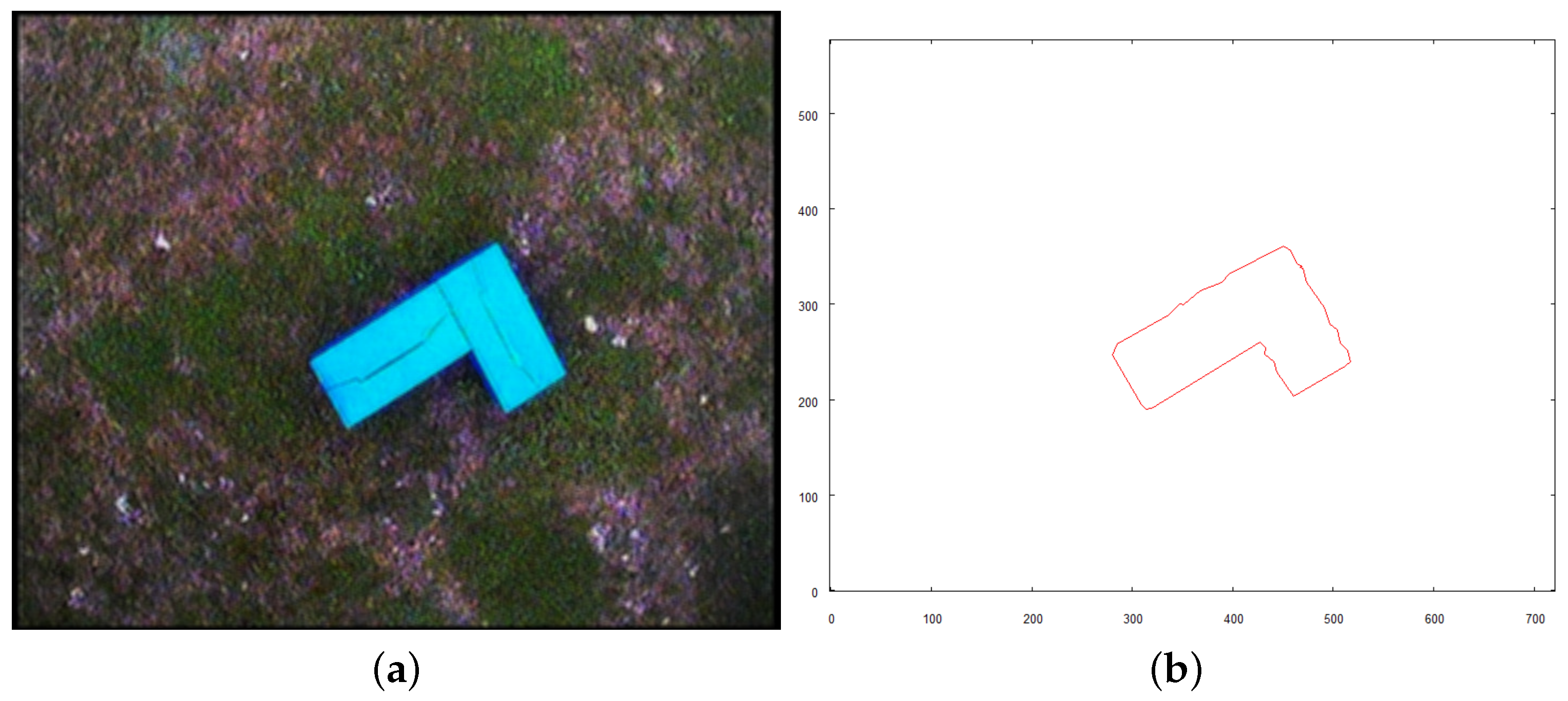
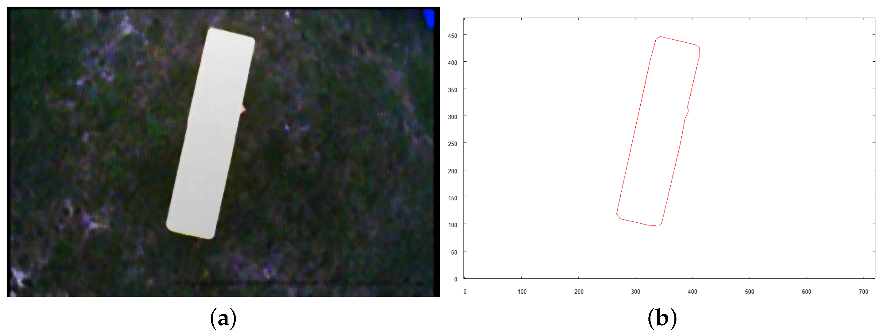
- Vectorization algorithm was used to obtain vector representation buildings from both pictures.
- Recognition method was used to search objects (objects) from small pictures in the overall map.
- When found, necessary pictures of prepared models were taken.
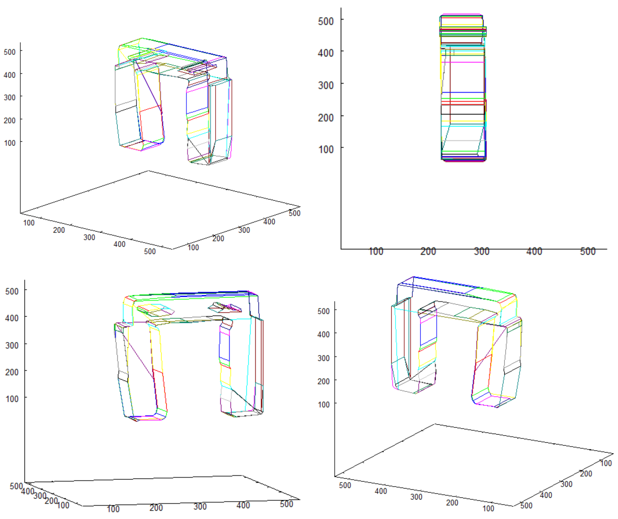
- Pictures were vectorized and, with the use of result data, 3D vector models of buildings were created.
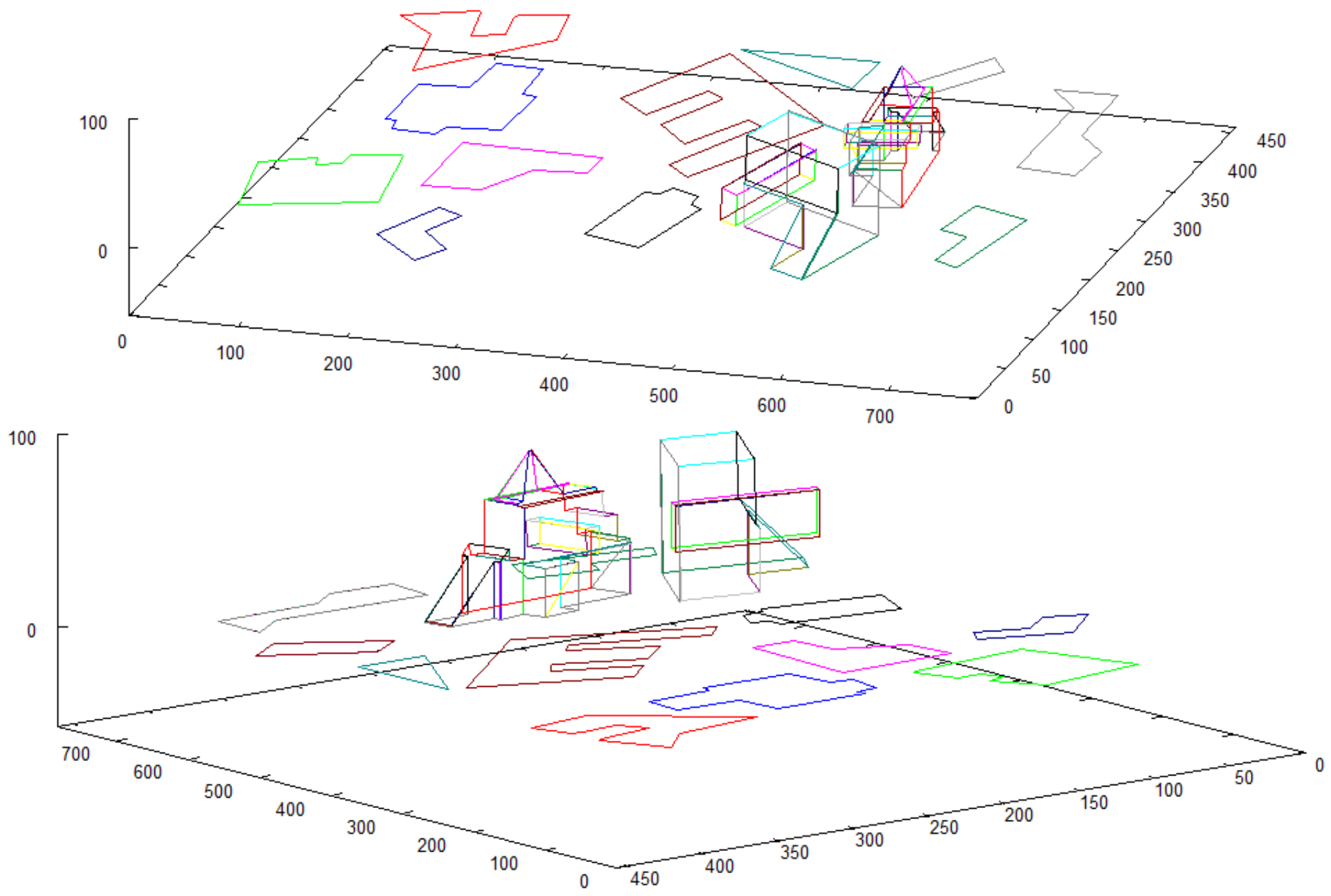
- Data structure holding vectorized shapes of objects on the overall map is created (vector map representation). 3D representations of buildings are added in their respective locations to obtain the enriched model of the scene.
- The coordinates of recognized objects are directly related to the centroids of their vector representations on the map of the scene (see the found objects in Figure 10).
- The scale and rotation are the direct output of the recognition method. These parameters are used to scale and rotate all vectors that create the 3D model of each structure.
3.2. Algorithms Applied on UAV
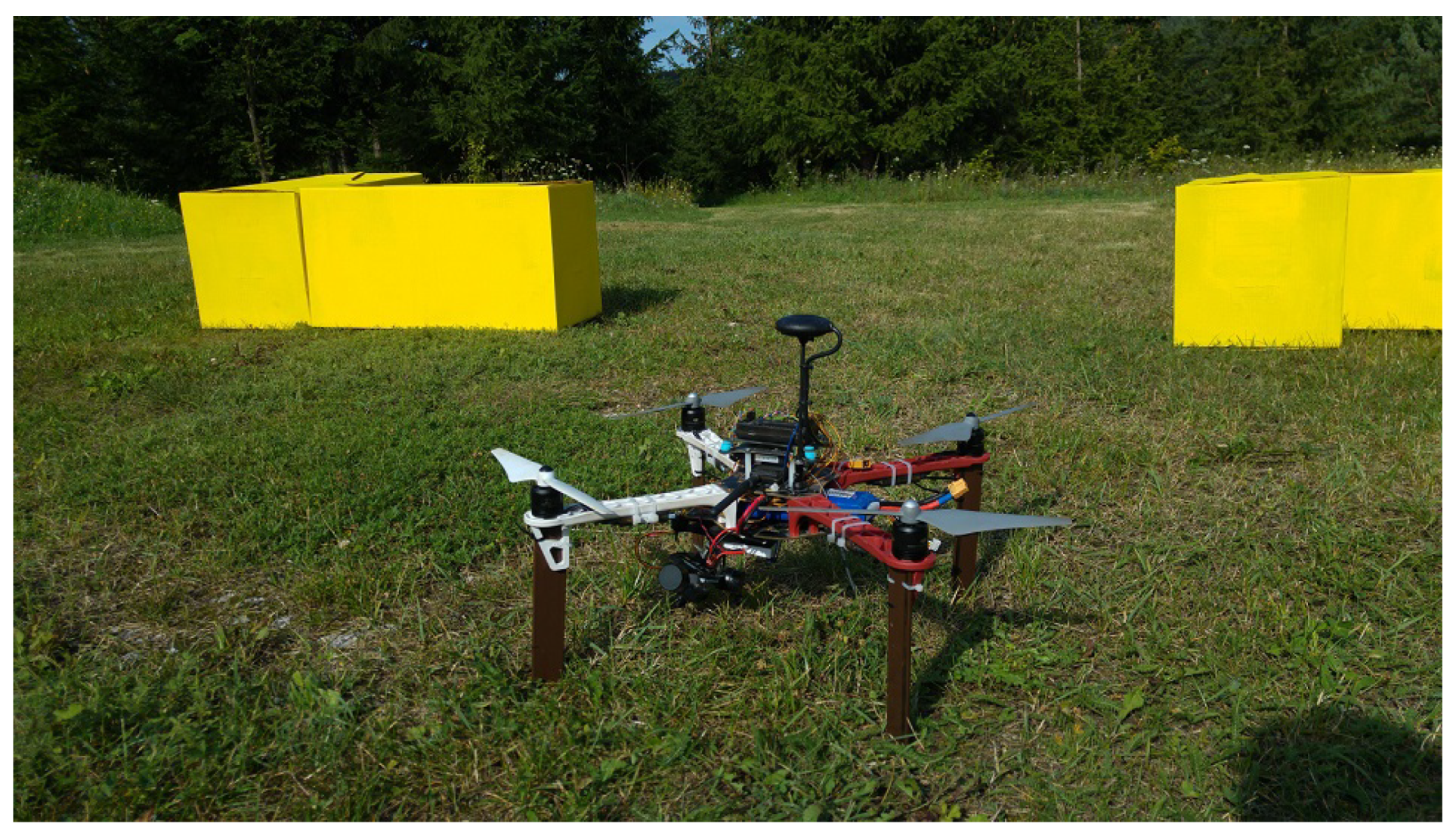
- The robot takes off and positions itself on a predefined altitude of 9 m above the examined scene.
- Its camera is positioned downwards and an overall picture of the scene is taken which is a base for creating the initial map of the area.
- Objects of predefined colors (red, blue, yellow) are identified in the scene. Each of them has to be photographed directly from above to reveal its exact shape. To achieve this, the target location where the robot has to be positioned is calculated. The altitude of the target location is arbitrarily set to 4 m. Each location is expressed by distance (in meters) the robot needs to move along x and y axis of the initial map from the current position to visit first, second, and subsequent identified objects.
- The robot visits each one of the objects hovers over it and takes an image from above.
- Once the object is recognized, the robot enters the examination mode.
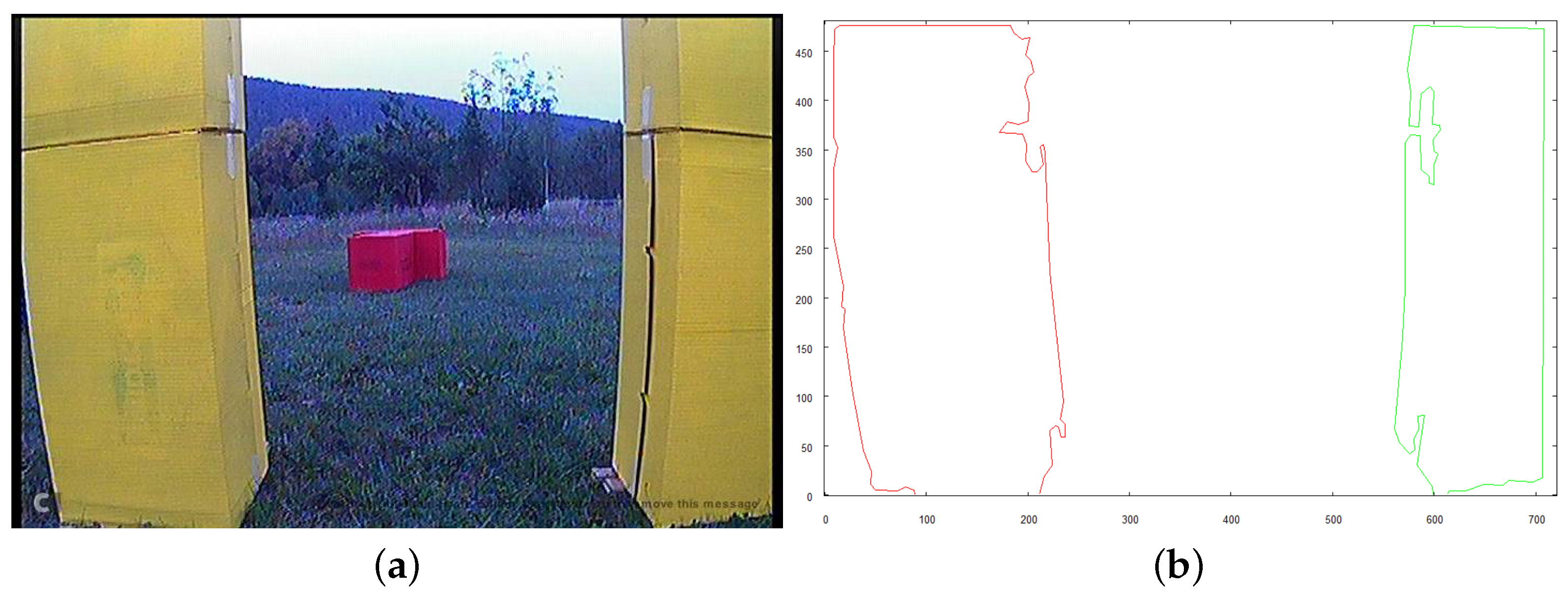
- To examine the object that was found, the robot calculates the target positions from which it will be able to take images of the object from three crucial directions: top, front, and right side of the examined structure.
- 3D representation of the examined object is created.
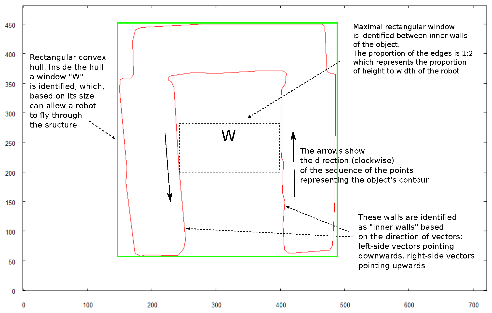
- Robot recognizes if it is possible to fly under the examined structure starting from any of the sides that it took an image from.
- If it is possible, the robot positions itself at a suitable position for collision-free flight under the structure.
- Mission is complete when the robot reaches the other side of the object without colliding.
- Median Filter [20] is applied with the window size of 7 pixels.
- Next, the Gamma Correction [21] is used to dim the image to avoid overexposure of some regions of the images. It is particularly necessary as the color extraction method used in the tests is based on saturation of the colors, which has to fall within specific boundaries.
- Scale:
- Rotation: (clockwise)
4. Discussion and Concluding Remarks
Author Contributions
Funding
Institutional Review Board Statement
Informed Consent Statement
Data Availability Statement
Conflicts of Interest
References
- Araar, O.; Aouf, N.; Dietz, J.L.V. Power pylon detection and monocular depth estimation from inspection UAVs. Ind. Robot. 2015, 43, 200–213. [Google Scholar] [CrossRef]
- Birk, A.; Wiggerich, B.; Bülow, H.; Pfingsthorn, M.; Schwertfeger, S. Safety, security, and rescue missions with an unmanned aerial vehicle (UAV). J. Intell. Robot. Syst. 2011, 64, 57–76. [Google Scholar] [CrossRef]
- Tomic, T.; Schmid, K.; Lutz, P.; Domel, A.; Kassecker, M.; Mair, E.; ILGrixa, I.L.; Ruess, F.; Suppa, M.; Burschka, D. Toward a fully autonomous UAV: Research platform for indoor and outdoor urban search and rescue. IEEE Robot. Autom. Mag. 2012, 19, 46–56. [Google Scholar] [CrossRef] [Green Version]
- Bajracharya, M.; Maimone, M.W.; Helmick, D. Autonomy for Mars rovers: Past present and future. Computer 2008, 41, 44–50. [Google Scholar] [CrossRef] [Green Version]
- Floreano, D.; Wood, R.J. Science, technology and the future of small autonomous drones. Nature 2015, 521, 460–466. [Google Scholar] [CrossRef] [Green Version]
- Bonin-Font, F.; Ortiz, A.; Oliver, G. Visual navigation for mobile robots: A survey. J. Intell. Robot. Syst. 2008, 53, 263–296. [Google Scholar] [CrossRef]
- Bielecki, A.; Śmigielski, P. Graph representation for two-dimensional scene understanding by the cognitive vision module. Int. J. Adv. Robot. Syst. 2017, 14, 1–14. [Google Scholar] [CrossRef] [Green Version]
- Rasouli, A.; Lanillos, P.; Cheng, G.; Tsotsos, J.K. Attention-based active visual search for mobile robots. Auton. Robot. 2020, 44, 131–146. [Google Scholar] [CrossRef] [Green Version]
- Lowry, S.; Sünderhauf, N.; Newman, P.; Leonard, J.J.; Cox, D.; Corke, P.; Milford, M.J. Visual place recognition: A survey. IEEE Trans. Robot. 2016, 32, 1–19. [Google Scholar] [CrossRef] [Green Version]
- Paul, R.; Newman, P. FAB-MAP 3D: Topological mapping with spatial and visual appearance. In Proceedings of the 2010 IEEE International Conference on Robotics and Automation, Anchorage, AK, USA, 3–7 May 2010; pp. 2649–2656. [Google Scholar]
- Grigorescu, S.; Trasnea, B.; Cocias, T.; Macesanu, G. A survey of deep learning techniques for autonomous driving. J. Field Robot. 2020, 37, 362–386. [Google Scholar] [CrossRef]
- Scaramuzza, D.; Achtelik, M.; Doitsidis, L.; Fraundorfer, F.; Kosmatopoulos, E.; Martinelli, A.; Achtelik, M.W.; Chli, M.; Chatzichristofis, S.A. Vision-controlled micro flying robots: From system design to autonomous navigation and mapping in GPS-denied environments. IEEE Robot. Autom. Mag. 2014, 21, 26–40. [Google Scholar] [CrossRef]
- Saripalli, S.; Montgomery, J.F.; Sukhatme, G.S. Visually-guided landing of an unmanned aerial vehicle. IEEE Trans. Robot. Autom. 2003, 19, 371–380. [Google Scholar] [CrossRef] [Green Version]
- Yang, S.; Scherer, S.A.; Schauwecker, K.; Zell, A. Autonomous landing of MAVs on an arbitrarily textured landing site using onboard monocular vision. J. Intell. Robot. Syst. 2014, 1-2, 27–43. [Google Scholar] [CrossRef] [Green Version]
- Conte, B.; Doherty, P. An integrated UAV navigation system based on aerial image matching. Proc. IEEE Aerosp. Conf. 2008, 2008, 3142–3151. [Google Scholar]
- Mur-Artal, R.; Montiel, J.M.M.; Tardós, J.D. ORB-SLAM: A versatile and accurate monocular SLAM system. IEEE Trans. Robot. 2015, 31, 1147–1163. [Google Scholar] [CrossRef] [Green Version]
- Bielecki, A.; Buratowski, T.; Śmigielski, P. Syntactic algorithm of two-dimensional scene analysis for unmanned flying vehicles. Lect. Notes Comput. Sci. 2012, 7594, 304–312. [Google Scholar]
- Bielecki, A.; Buratowski, T.; Śmigielski, P. Recognition of two-dimensional representation of urban environment for autonomous flying agents. Expert Syst. Appl. 2013, 30, 3623–3633. [Google Scholar] [CrossRef]
- Bielecki, A.; Buratowski, T.; Śmigielski, P. Three-dimensional urban-type scene representation in vision system of unmanned flying vehicles. Lect. Notes Comput. Sci. 2014, 8467, 662–671. [Google Scholar]
- Huang, T.; Yang, G.; Tang, G. A fast two-dimensional median filtering algorithm. IEEE Trans. Acoust. Speech, Signal Process. 1979, 27, 13–18. [Google Scholar] [CrossRef] [Green Version]
- Huang, S.C.; Cheng, F.C.; Chiu, Y.S. Efficient contrast enhancement using adaptive gamma correction with weighting distribution. IEEE Trans. Image Process. 2013, 22, 1032–1041. [Google Scholar] [CrossRef] [PubMed]
- Miller, I.; Campbell, M.; Huttenlocher, D. Efficient unbiased tracking of multiple dynamic obstacles under large viewpoint changes. IEEE Trans. Robot. 2011, 27, 29–46. [Google Scholar] [CrossRef]
- Vatavu, A.; Nedevschi, S. Real-time modeling of dynamic environments in traffic scenarios using a stereo-vision system. In Proceedings of the 2012 15th International IEEE Conference on Intelligent Transportation Systems, Anchorage, AK, USA, 16–19 September 2012; pp. 722–727. [Google Scholar]
- Wang, H.; Wang, B.; Liu, B.; Meng, X.; Yang, G. Pedestrian recognition and tracking using 3D LiDAR for autonomous vehicle. Robot. Auton. Syst. 2017, 88, 71–78. [Google Scholar] [CrossRef]
- Steger, C.; Ulrich, M.; Wiedemann, C. Machine Vision Algorithm and Applications; Wiley: Hoboken, NJ, USA, 2018. [Google Scholar]
- Fischler, M.; Bolles, R. Random sample consensus: A paradigm for model fitting with applications to image analysis and automated cartography. Commun. ACM 1981, 24, 381–395. [Google Scholar] [CrossRef]
- Rolfes, S.; Rendas, M.J. Shape recognition: A fuzzy approach. In Proceedings of the IEEE International Conference on Robotics and Automation, Leuven, Belgium, 20–21 May 1998; pp. 3382–3387. [Google Scholar]
- Decker, P.; Thierfelder, S.; Paulus, D.; Grzegorzek, M. Dense statistic versus sparse feature-based approach for 3d object recognition. Pattern Recognit. Image Anal. 2011, 21, 238–241. [Google Scholar] [CrossRef]
- Li, J.; Mei, X.; Prokhorov, D.; Tao, D. Deep neural network for structural prediction and lane detection in traffic scene. IEEE Trans. Neural Networks Learn. Syst. 2017, 28, 690–703. [Google Scholar] [CrossRef] [PubMed] [Green Version]
- Alatise, M.B.; Hancke, G.P. Pose estimation of a mobile robot based on fusion of IMU data and vision data using an extended Kalman filter. Sensors 2017, 17, 2164. [Google Scholar] [CrossRef] [Green Version]
- Canny, J. Finding Edges and Lines in Images; Tech. Rep.; M.I.T. Artificial Intelligence Lab.: Cambridge, MA, USA, 1983. [Google Scholar]
- Śmigielski, P.; Raczyński, M.; Gosek, Ł. Visual simulator for MAVlink-protocol-based UAV, applied for search and analyze task. In Proceedings of the 2017 Federated Conference on Computer Science and Information Systems, Prague, Czech Republic, 3–6 September 2017; pp. 193–201. [Google Scholar]


Publisher’s Note: MDPI stays neutral with regard to jurisdictional claims in published maps and institutional affiliations. |
© 2021 by the authors. Licensee MDPI, Basel, Switzerland. This article is an open access article distributed under the terms and conditions of the Creative Commons Attribution (CC BY) license (https://creativecommons.org/licenses/by/4.0/).
Share and Cite
Bielecki, A.; Śmigielski, P. Three-Dimensional Outdoor Analysis of Single Synthetic Building Structures by an Unmanned Flying Agent Using Monocular Vision. Sensors 2021, 21, 7270. https://doi.org/10.3390/s21217270
Bielecki A, Śmigielski P. Three-Dimensional Outdoor Analysis of Single Synthetic Building Structures by an Unmanned Flying Agent Using Monocular Vision. Sensors. 2021; 21(21):7270. https://doi.org/10.3390/s21217270
Chicago/Turabian StyleBielecki, Andrzej, and Piotr Śmigielski. 2021. "Three-Dimensional Outdoor Analysis of Single Synthetic Building Structures by an Unmanned Flying Agent Using Monocular Vision" Sensors 21, no. 21: 7270. https://doi.org/10.3390/s21217270
APA StyleBielecki, A., & Śmigielski, P. (2021). Three-Dimensional Outdoor Analysis of Single Synthetic Building Structures by an Unmanned Flying Agent Using Monocular Vision. Sensors, 21(21), 7270. https://doi.org/10.3390/s21217270