
Comparison between Different Channel Coding Techniques for IEEE 802.11be within Factory Automation Scenarios


Abstract
:1. Introduction
2. IEEE 802.11
2.1. State of the Art of IEEE 802.11
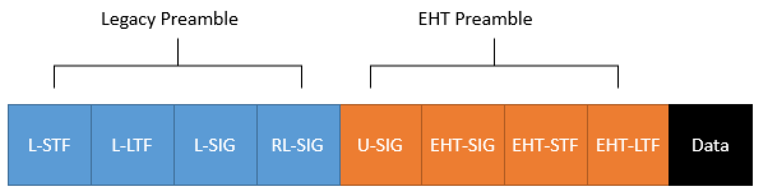
2.2. IEEE 802.11be PPDU Format
3. Discussion on Factory Automation Scenarios
3.1. Proposed Industrial Channel Models
3.2. Discussion on Factory Automation Wireless System Design Issues
4. Channel Coding Techniques
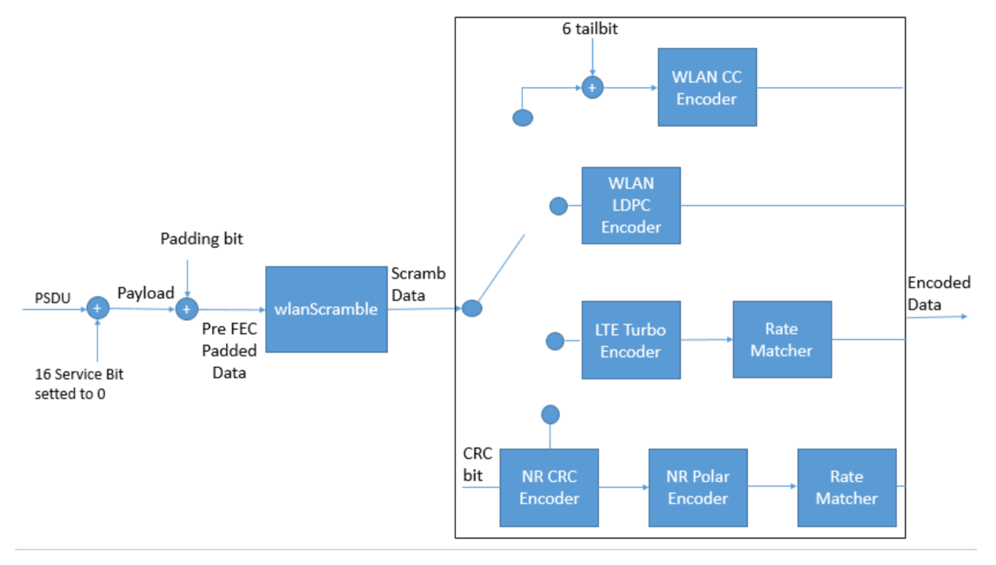
4.1. WLAN Convolutional Codes
4.2. WLAN LDPC Codes
4.3. LTE Turbo Codes
4.4. New Radio Polar Codes
5. Proposed Channel Coding Platform for IEEE 802.11be
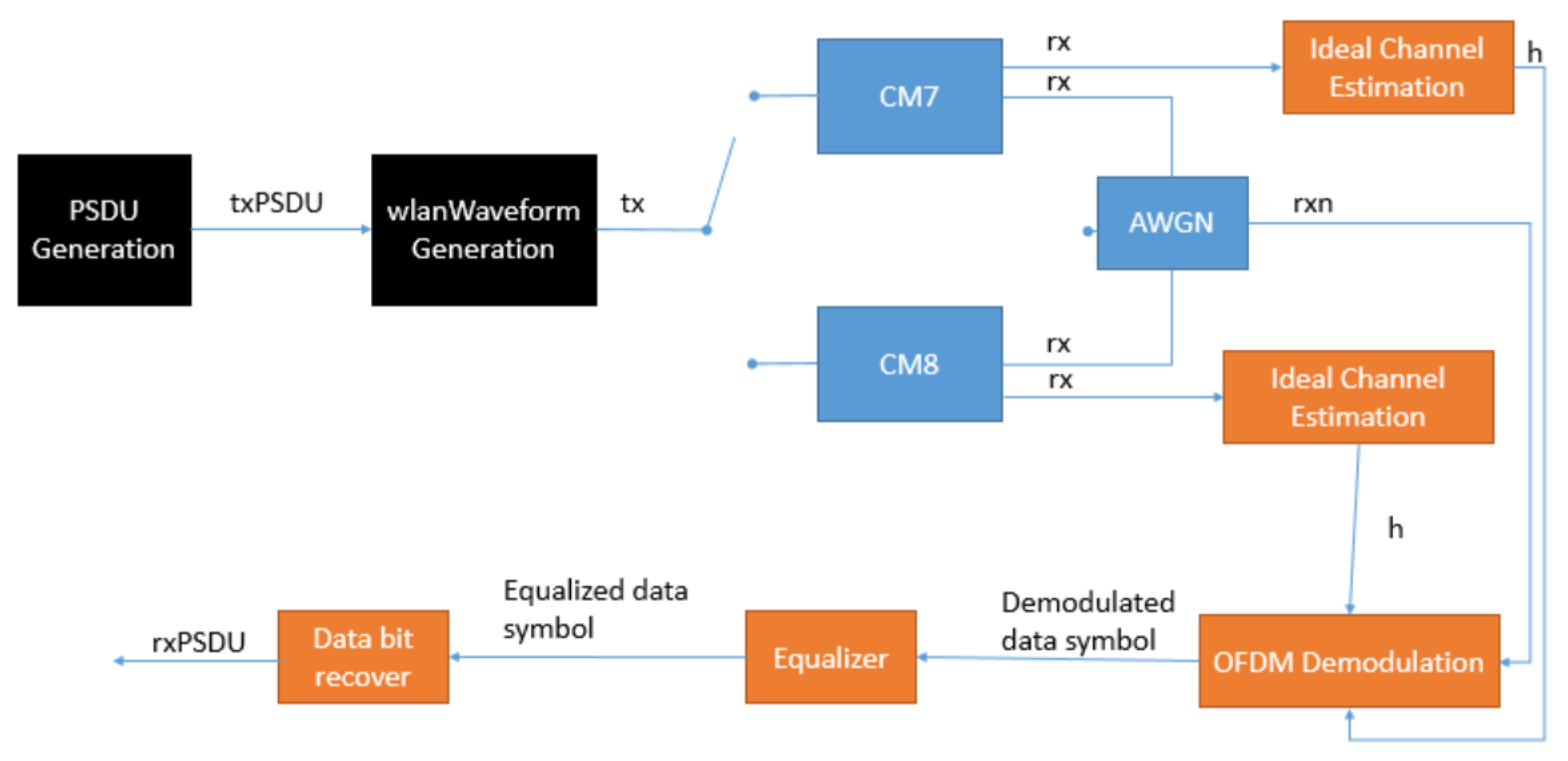
5.1. Platform Architecture
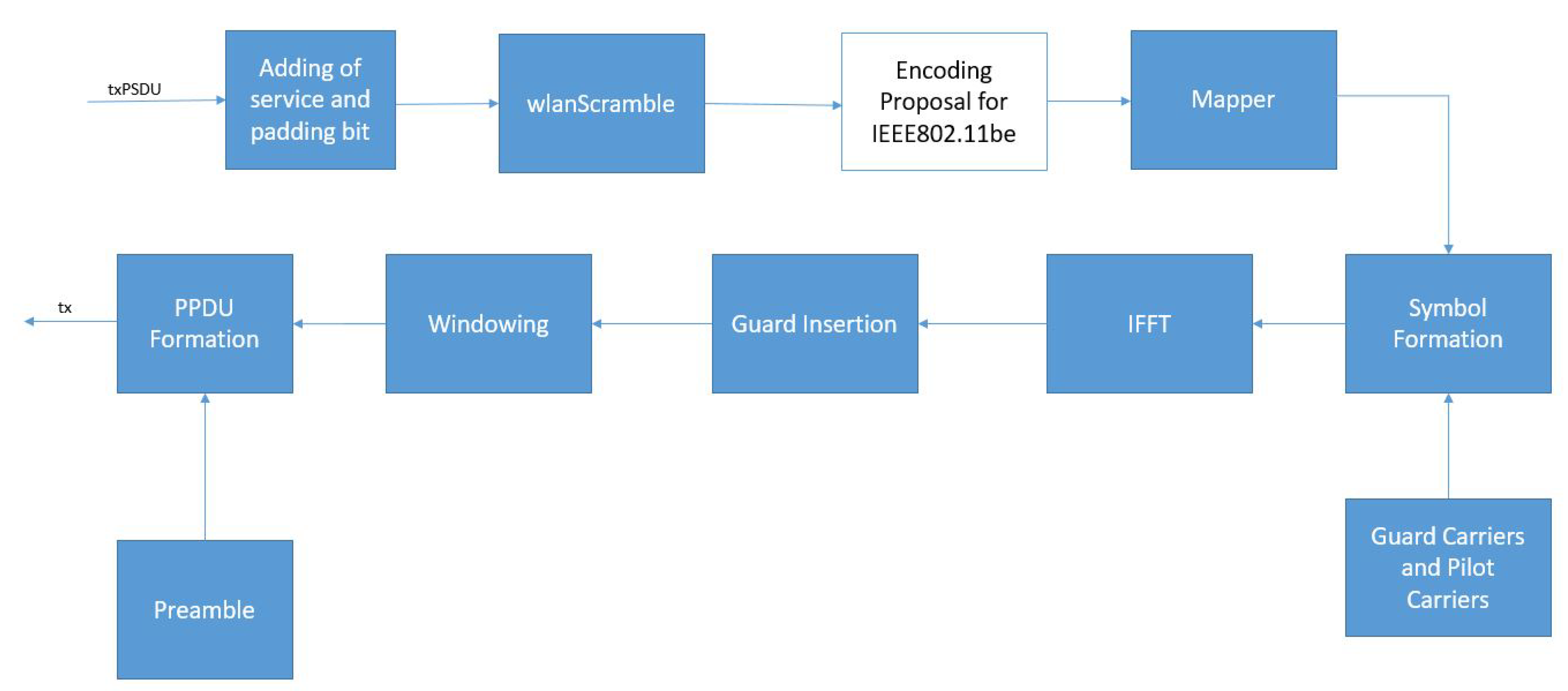
5.2. Data Transmission Block
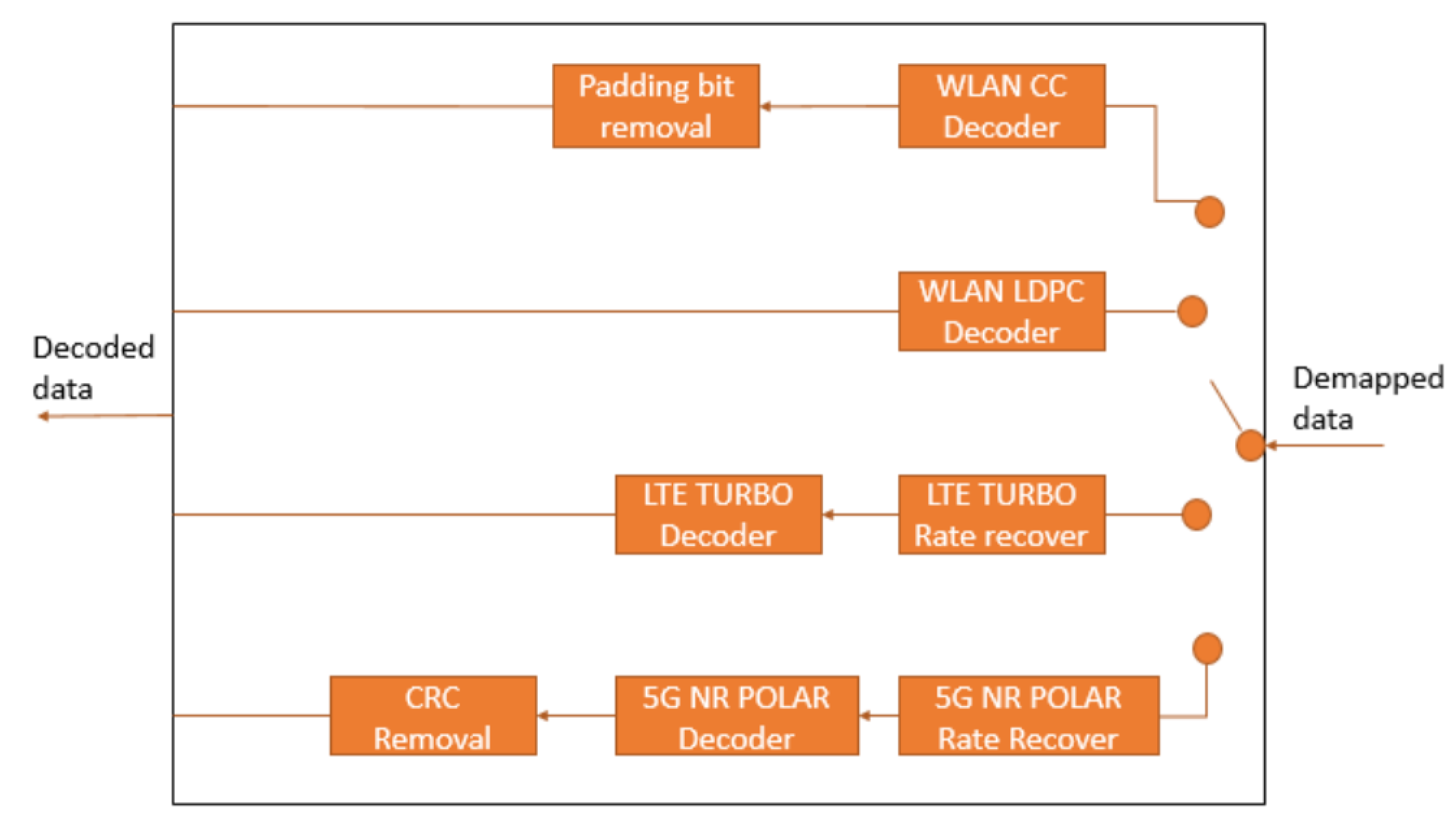
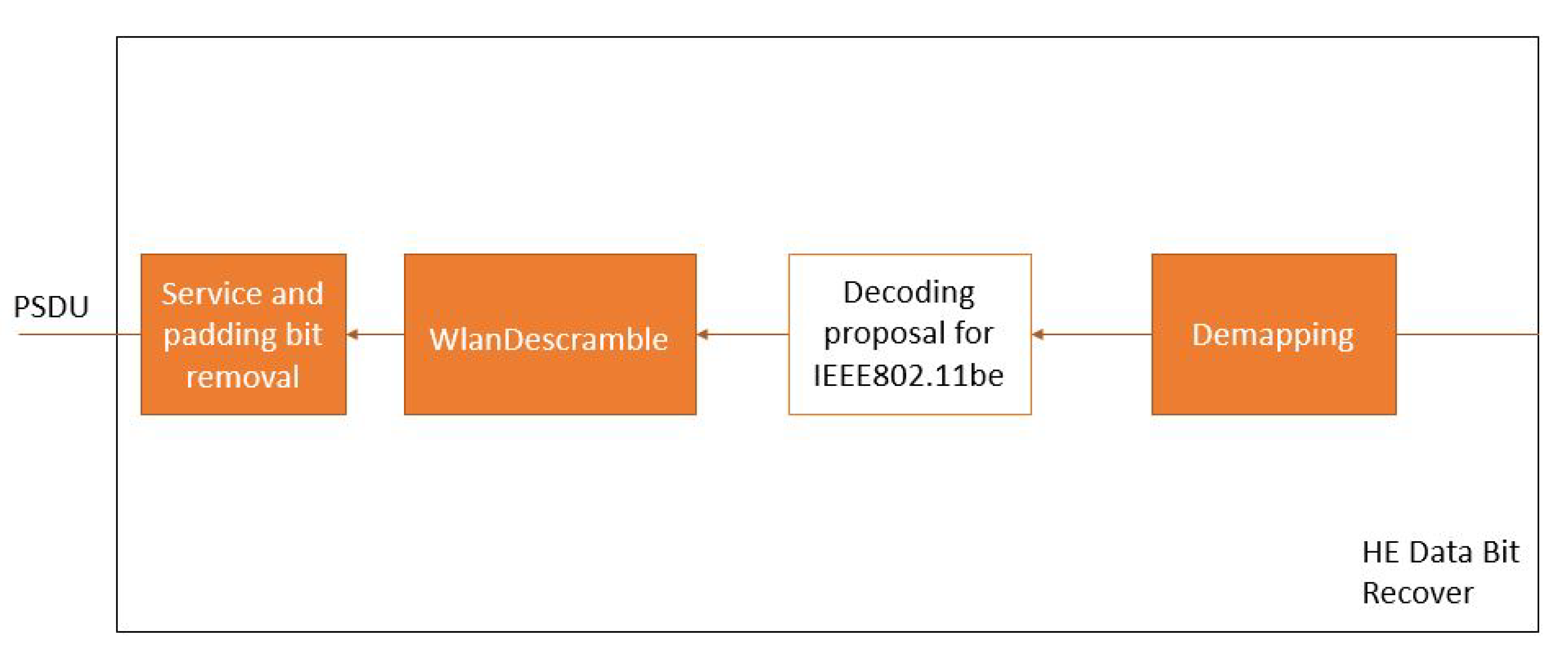
5.3. Data Bit Recover Block
5.4. System Model Parameters
5.5. Channel Coding Configurations
6. Results
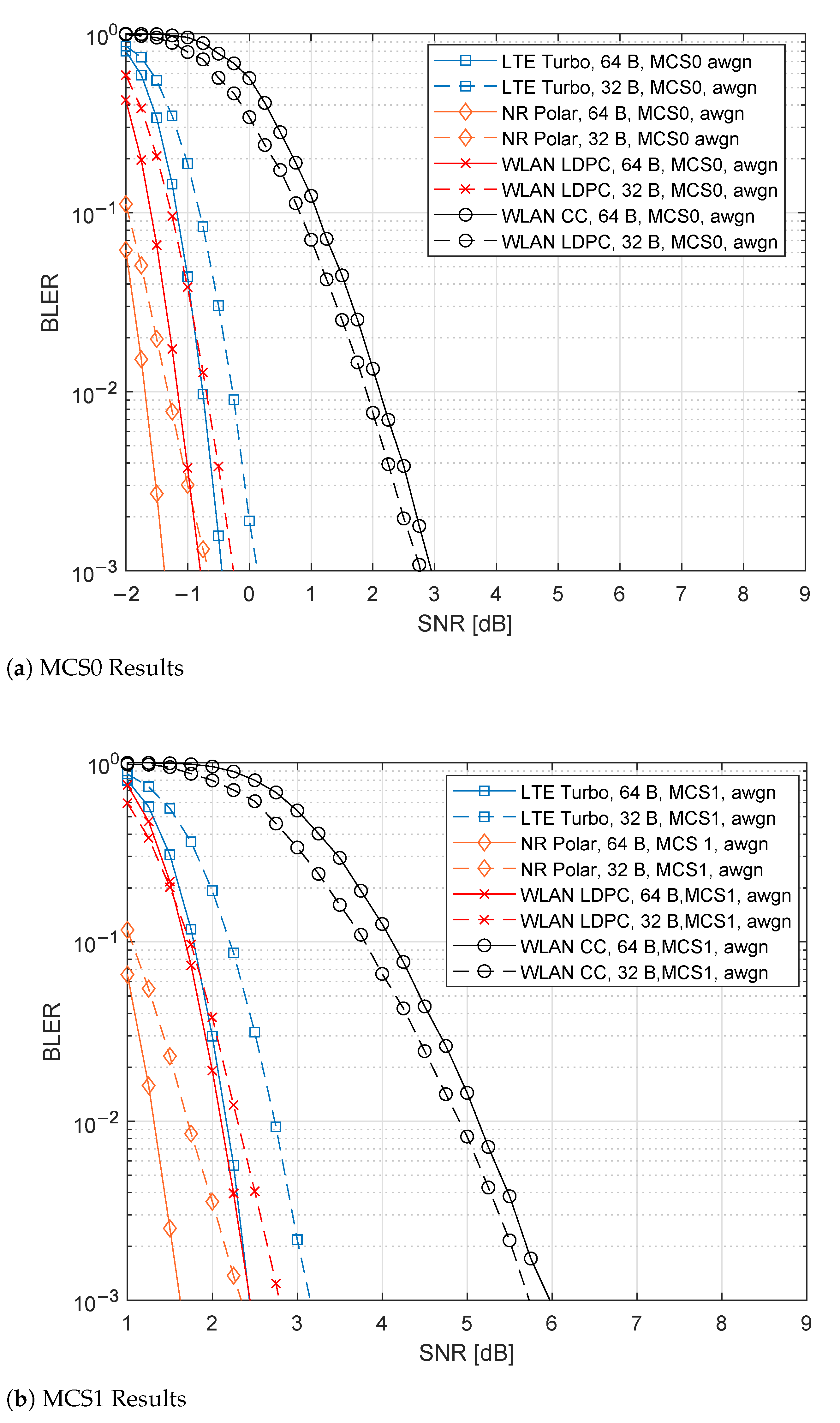
6.1. AWGN Results
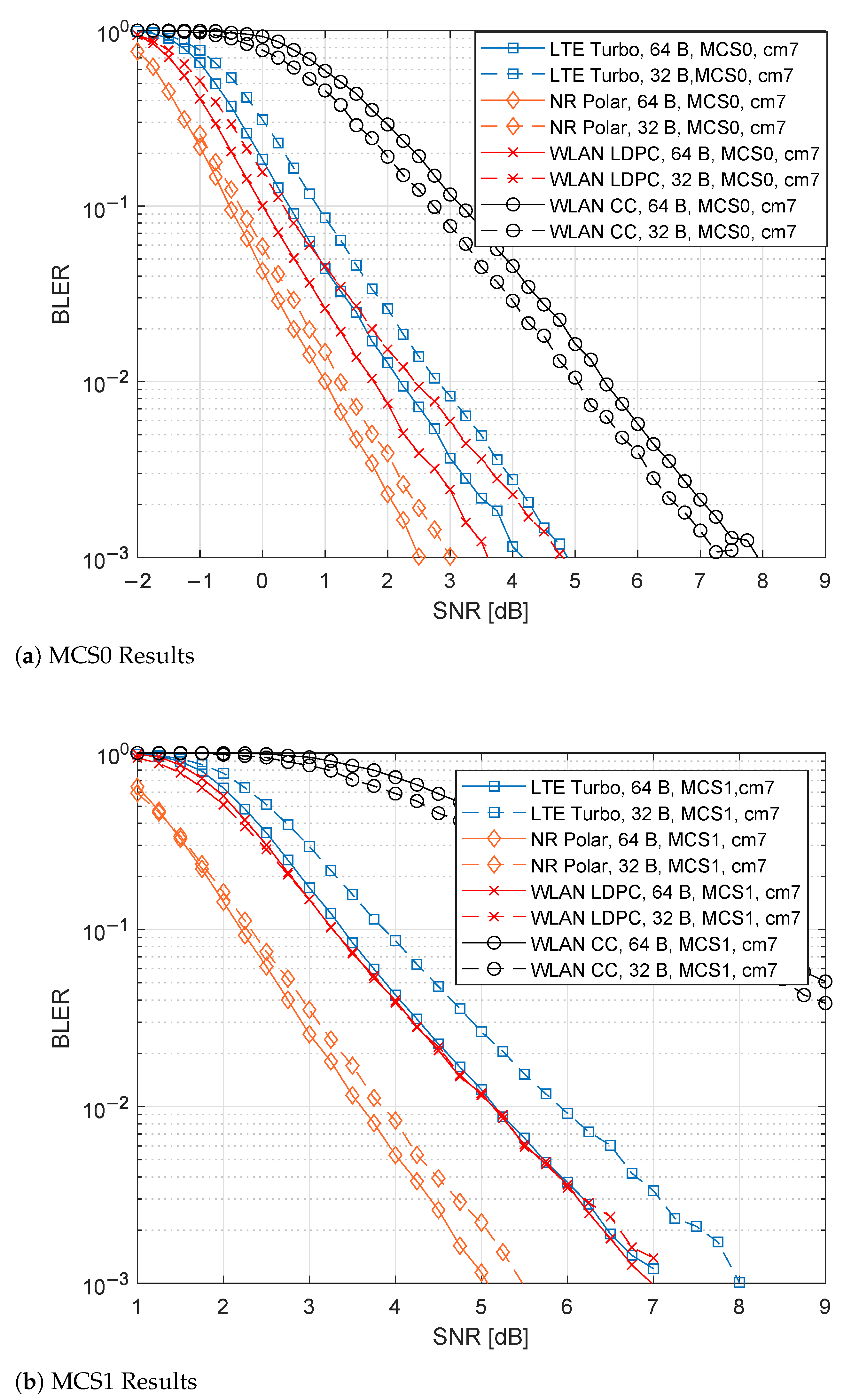
6.2. CM7 Results
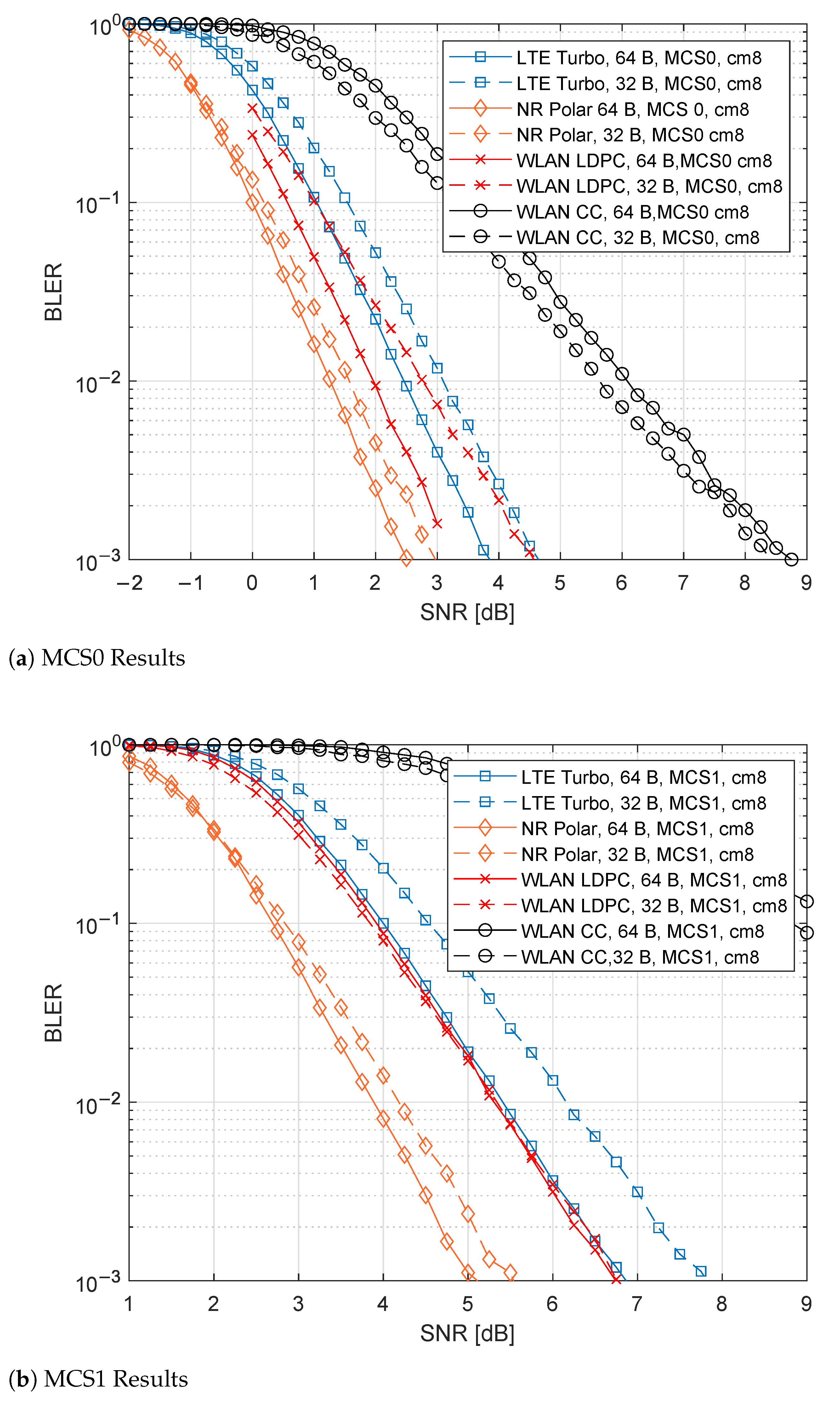
6.3. CM8 Results
6.4. Discussion
7. Conclusions
Author Contributions
Funding
Institutional Review Board Statement
Informed Consent Statement
Data Availability Statement
Conflicts of Interest
References
- Sutton, G.J.; Zeng, J.; Liu, R.P.; Ni, W.; Nguyen, D.N.; Jayawickrama, B.A.; Huang, X.; Abolhasan, M.; Zhang, Z.; Dutkiewicz, E.; et al. Enabling Technologies for Ultra-Reliable and Low Latency Communications: From PHY and MAC Layer Perspectives. IEEE Commun. Surv. Tutor. 2019, 21, 2488–2524. [Google Scholar] [CrossRef]
- Montgomery, K.; Candell, R.; Liu, Y.; Hany, M. Wireless User Requirements for the Factory Workcell; NIST: Gaithersburg, MD, USA, 2019. [Google Scholar] [CrossRef]
- Schulz, P.; Matthe, M.; Klessig, H.; Simsek, M.; Fettweis, G.; Ansari, J.; Ashraf, S.A.; Almeroth, B.; Voigt, J.; Riedel, I.; et al. Latency Critical IoT Applications in 5G: Perspective on the Design of Radio Interface and Network Architecture. IEEE Commun. Mag. 2017, 55, 70–78. [Google Scholar] [CrossRef]
- Åkerberg, J.; Gidlund, M.; Björkman, M. Future research challenges in wireless sensor and actuator networks targeting industrial automation. In Proceedings of the 2011 9th IEEE International Conference on Industrial Informatics, Lisbon, Portugal, 26–29 July 2011; pp. 410–415. [Google Scholar] [CrossRef]
- Candell, R.; Kashef, M. Industrial wireless: Problem space, success considerations, technologies, and future direction. In Proceedings of the 2017 Resilience Week (RWS), Wilmington, DE, USA, 18–22 September 2017; pp. 133–139. [Google Scholar] [CrossRef]
- Luvisotto, M.; Pang, Z.; Dzung, D. High-Performance Wireless Networks for Industrial Control Applications: New Targets and Feasibility. Proc. IEEE 2019, 107, 1074–1093. [Google Scholar] [CrossRef]
- Cavalcanti, D.; Perez-Ramirez, J.; Rashid, M.M.; Fang, J.; Galeev, M.; Stanton, K.B. Extending Accurate Time Distribution and Timeliness Capabilities Over the Air to Enable Future Wireless Industrial Automation Systems. Proc. IEEE 2019, 107, 1132–1152. [Google Scholar] [CrossRef]
- Seijo, O.; Lopez-Fernandez, J.A.; Val, I. w-SHARP: Implementation of a High-Performance Wireless Time-Sensitive Network for Low Latency and Ultra-low Cycle Time Industrial Applications. IEEE Trans. Ind. Inform. 2021, 17, 3651–3662. [Google Scholar] [CrossRef]
- Luvisotto, M.; Pang, Z.; Dzung, D.; Zhan, M.; Jiang, X. Physical Layer Design of High-Performance Wireless Transmission for Critical Control Applications. IEEE Trans. Ind. Inform. 2017, 13, 2844–2854. [Google Scholar] [CrossRef]
- Chen, L.; Yue, D.; Dou, C.; Cheng, Z.; Chen, J. Robustness of cyber-physical power systems in cascading failure: Survival of interdependent clusters. Int. J. Electr. Power Energy Syst. 2020, 114, 105374. [Google Scholar] [CrossRef]
- Costa, R.; Lau, J.; Portugal, P.; Vasques, F.; Moraes, R. Handling real-time communication in infrastructured IEEE 802.11 wireless networks: The RT-WiFi approach. J. Commun. Netw. 2019, 21, 319–334. [Google Scholar] [CrossRef]
- Mahmood, A.; Sauter, T.; Trsek, H.; Exel, R. Methods and performance aspects for wireless clock synchronization in IEEE 802.11 for the IoT. In Proceedings of the 2016 IEEE World Conference on Factory Communication Systems (WFCS), Aveiro, Portugal, 3–6 May 2016; pp. 1–4. [Google Scholar] [CrossRef]
- Shen, W.; Zhang, T.; Barac, F.; Gidlund, M. PriorityMAC: A Priority-Enhanced MAC Protocol for Critical Traffic in Industrial Wireless Sensor and Actuator Networks. IEEE Trans. Ind. Inform. 2014, 10, 824–835. [Google Scholar] [CrossRef]
- Aijaz, A. High-Performance Industrial Wireless: Achieving Reliable and Deterministic Connectivity Over IEEE 802.11 WLANs. IEEE Open J. Ind. Electron. Soc. 2020, 1, 28–37. [Google Scholar] [CrossRef] [Green Version]
- Seijo, O.; Fernandez, Z.; Val, I.; Lopez-Fernandez, J.A. SHARP: Towards the Integration of Time-Sensitive Communications in Legacy LAN/WLAN. In Proceedings of the 2018 IEEE Globecom Workshops (GC Wkshps), Abu Dhabi, United Arab Emirates, 9–13 December 2018; pp. 1–7. [Google Scholar] [CrossRef]
- Seijo, O.; Fernandez, Z.; Val, I.; Lopez-Fernandez, J.A. SHARP: A novel hybrid architecture for industrial wireless sensor and actuator networks. In Proceedings of the 2018 14th IEEE International Workshop on Factory Communication Systems (WFCS), Imperia, Italy, 13–15 June 2018; pp. 1–10. [Google Scholar] [CrossRef]
- Pang, Z.; Luvisotto, M.; Dzung, D. Wireless High-Performance Communications: The Challenges and Opportunities of a New Target. IEEE Ind. Electron. Mag. 2017, 11, 20–25. [Google Scholar] [CrossRef]
- Shirvanimoghaddam, M.; Mohammadi, M.S.; Abbas, R.; Minja, A.; Yue, C.; Matuz, B.; Han, G.; Lin, Z.; Liu, W.; Li, Y.; et al. Short Block-Length Codes for Ultra-Reliable Low Latency Communications. IEEE Commun. Mag. 2019, 57, 130–137. [Google Scholar] [CrossRef] [Green Version]
- Shao, S.; Hailes, P.; Wang, T.Y.; Wu, J.Y.; Maunder, R.G.; Al-Hashimi, B.M.; Hanzo, L. Survey of Turbo, LDPC, and Polar Decoder ASIC Implementations. IEEE Commun. Surv. Tutor. 2019, 21, 2309–2333. [Google Scholar] [CrossRef] [Green Version]
- Dujovne, D.; Turletti, T.; Filali, F. A Taxonomy of IEEE 802.11 Wireless Parameters and Open Source Measurement Tools. IEEE Commun. Surv. Tutor. 2010, 12, 249–262. [Google Scholar] [CrossRef] [Green Version]
- Deng, C.; Fang, X.; Han, X.; Wang, X.; Yan, L.; He, R.; Long, Y.; Guo, Y. IEEE 802.11be Wi-Fi 7: New Challenges and Opportunities. IEEE Commun. Surv. Tutor. 2020, 22, 2136–2166. [Google Scholar] [CrossRef]
- Lopez-Perez, D.; Garcia-Rodriguez, A.; Galati-Giordano, L.; Kasslin, M.; Doppler, K. IEEE 802.11be Extremely High Throughput: The Next Generation of Wi-Fi Technology Beyond 802.11ax. IEEE Commun. Mag. 2019, 57, 113–119. [Google Scholar] [CrossRef] [Green Version]
- Khorov, E.; Levitsky, I.; Akyildiz, I.F. Current Status and Directions of IEEE 802.11be, the Future Wi-Fi 7. IEEE Access 2020, 8, 88664–88688. [Google Scholar] [CrossRef]
- Garcia-Rodriguez, A.; López-Pérez, D.; Galati-Giordano, L.; Geraci, G. IEEE 802.11be: Wi-Fi 7 Strikes Back. IEEE Commun. Mag. 2021, 59, 102–108. [Google Scholar] [CrossRef]
- Molisch, A.; Balakrishnan, K.; Cassioli, D.; Chong, C.; Emami, S.; Fort, A.; Karedal, J.; Kunisch, J.; Schantz, H.; Schuster, U.; et al. IEEE 802.15.4a Channel Model-Final Report. Converging: Technology, Work and Learning. Australian Government Printing Service. 2004. Available online: https://www.ieee802.org/15/pub/04/15-04-0662-02-004a-channel-model-final-report-r1.pdf (accessed on 28 October 2021).
- Croonenbroeck, R.; Underberg, L.; Wulf, A.; Kays, R. Measurements for the development of an enhanced model for wireless channels in industrial environments. In Proceedings of the 2017 IEEE 13th International Conference on Wireless and Mobile Computing, Networking and Communications (WiMob), Rome, Italy, 9–11 October 2017; pp. 1–8. [Google Scholar] [CrossRef]
- Wassie, D.A.; Rodriguez, I.; Berardinelli, G.; Tavares, F.M.L.; Sorensen, T.B.; Mogensen, P. Radio Propagation Analysis of Industrial Scenarios within the Context of Ultra-Reliable Communication. In Proceedings of the 2018 IEEE 87th Vehicular Technology Conference (VTC Spring), Porto, Portugal, 3–6 June 2018; pp. 1–6. [Google Scholar] [CrossRef] [Green Version]
- Iradier, E.; Fanari, L.; Bilbao, I.; Montalban, J.; Angueira, P.; Seijo, O.; Val, I. Analysis of NOMA-Based Retransmission Schemes for Factory Automation Applications. IEEE Access 2021, 9, 29541–29554. [Google Scholar] [CrossRef]
- Montalban, J.; Iradier, E.; Angueira, P.; Seijo, O.; Val, I. NOMA-Based 802.11n for Industrial Automation. IEEE Access 2020, 8, 168546–168557. [Google Scholar] [CrossRef]
- Coşkun, M.C.; Durisi, G.; Jerkovits, T.; Liva, G.; Ryan, W.; Stein, B.; Steiner, F. Efficient error-correcting codes in the short blocklength regime. Phys. Commun. 2019, 34, 66–79. [Google Scholar] [CrossRef] [Green Version]
- Elias, P. Coding for noisy channels. IRE Conv. Rec. 1955, 3 Pt 4, 37–46. [Google Scholar]
- Ramdani, A.Z.; Adiono, T. A novel algorithm of tail biting convolutional code decoder for low cost hardware implementation. In Proceedings of the 2015 International Symposium on Intelligent Signal Processing and Communication Systems (ISPACS), Nusa Dua Bali, Indonesia, 9–12 November 2015; pp. 241–245. [Google Scholar] [CrossRef]
- Gallager, R. Low-density parity-check codes. IRE Trans. Inf. Theory 1962, 8, 21–28. [Google Scholar] [CrossRef] [Green Version]
- Davey, M.C.; MacKay, D. Low-density parity check codes over GF(q). IEEE Commun. Lett. 1998, 2, 165–167. [Google Scholar] [CrossRef]
- Qu, Q.; Li, B.; Yang, M.; Yan, Z.; Yang, A.; Yu, J.; Gan, M.; Li, Y.; Yang, X.; Aboul-Magd, O.; et al. Survey and Performance Evaluation of the Upcoming Next Generation WLAN Standard-IEEE 802.11ax. arXiv 2018, arXiv:cs.NI/1806.05908. [Google Scholar] [CrossRef]
- Berrou, C.; Glavieux, A.; Thitimajshima, P. Near Shannon limit error-correcting coding and decoding: Turbo-codes. 1. In Proceedings of the ICC ’93-IEEE International Conference on Communications, Geneva, Switzerland, 23–26 May 1993; Volume 2, pp. 1064–1070. [Google Scholar] [CrossRef]
- Chen, H.; Maunder, R.G.; Hanzo, L. A Survey and Tutorial on Low-Complexity Turbo Coding Techniques and a Holistic Hybrid ARQ Design Example. IEEE Commun. Surv. Tutor. 2013, 15, 1546–1566. [Google Scholar] [CrossRef] [Green Version]
- Arikan, E. Channel Polarization: A Method for Constructing Capacity-Achieving Codes for Symmetric Binary-Input Memoryless Channels. IEEE Trans. Inf. Theory 2009, 55, 3051–3073. [Google Scholar] [CrossRef]
- Kaykac Egilmez, Z.B.; Xiang, L.; Maunder, R.G.; Hanzo, L. The Development, Operation and Performance of the 5G Polar Codes. IEEE Commun. Surv. Tutor. 2020, 22, 96–122. [Google Scholar] [CrossRef] [Green Version]
- IEEE Standard for Information Technology–Telecommunications and Information Exchange between Systems Local and Metropolitan Area Networks–Specific Requirements Part 11: Wireless LAN Medium Access Control (MAC) and Physical Layer (PHY) Specifications Amendment 1: Enhancements for High-Efficiency WLAN. In IEEE Std 802.11ax-2021 (Amendment to IEEE Std 802.11-2020); IEEE: Piscataway, NJ, USA, 2021; pp. 1–767. [CrossRef]
- 3GPP. Digital cellular telecommunications system (Phase 2+) (GSM); Universal Mobile Telecommunications System (UMTS); LTE; 5G. In 3rd Generation Partnership Project (3GPP); Technical Report (TR) 121 915; 3GPP: Sophia Antipolis, France, 2019; Version 15.0.0. [Google Scholar]
- 3GPP. LTE. Evolved Universal Terrestrial Radio Access (E-UTRA); Multiplexing and channel coding (3GPP TS 36.212 version 15.2.1 Release 15). In 3rd Generation Partnership Project (3GPP); Technical Specification (TS) 136 212; 3GPP: Sophia Antipolis, France, 2018; Version 15.2.1. [Google Scholar]
- Li, H.; Park, Y.S.; Zhang, Z. Reconfigurable architecture and automated design flow for rapid FPGA-based LDPC code emulation. In Proceedings of the ACM/SIGDA International Symposium on Field Programmable Gate Arrays-FPGA ’12; ACM Press: New York, NY, USA, 2012; p. 167. [Google Scholar] [CrossRef]
- Fan, Y.; Xia, C.; Chen, J.; Tsui, C.Y.; Jin, J.; Shen, H.; Li, B. A Low-Latency List Successive-Cancellation Decoding Implementation for Polar Codes. IEEE J. Sel. Areas Commun. 2016, 34, 303–317. [Google Scholar] [CrossRef] [Green Version]


| Use Case Category | PER | Control Cycle Time [ms] | Payload Length [B] | Applicative Example |
|---|---|---|---|---|
| Safety | t ≤ 0.5 | 6–24 | Alarms | |
| Critical | 0.25 < t ≤ 12 | 8–1024 | Close-loops controls | |
| Non-Critical | 4 < t ≤ 50 | 12–33k | Monitoring operations |
| Parameters | Values |
|---|---|
| PSDU Lengths [B] | 32, 64 |
| Modulation | QPSK, BPSK |
| Code Rate | 1/2 |
| Channel Models | AWGN, CM7, CM8 |
| Channel Parameters (AWGN is not included) | Mean = 0 dB, = 6 dB |
| BLER threshold | |
| Transmitted Frames | |
| SNR steps [dB] | 0.25 |
| Parameters | Encoding Details | Presence of Rate Matcher | Decoding Details |
|---|---|---|---|
| WLAN CC | Tail-bit sequence of 6 bit | No | Soft Decoding |
| WLAN LDPC | Considered blocks: 648, 1296 | No | BP with 12 iterations |
| 5G NR Polar | Considered 5G NR CRCs: 11 bit, 24 it type B | Yes | SCL with List size of 8 |
| LTE Turbo | It follows the guidelines of the standard | Yes | Max-Log-MAP with 12 iterations |
| Parameters | LDPC | Polar |
|---|---|---|
| Decoding Algorithm | BP | SCL |
| Model | Li et al. | Fan et al. |
| Parallelism | Full | Semi |
| Required Clock Cycles | ||
| P | N | 64 |
| Iterations | 10 | no |
| Clock Cycles for N = 128 B | 5 | 32 |
| Clock Cycles for N = 64 B | 5 | 16 |
Publisher’s Note: MDPI stays neutral with regard to jurisdictional claims in published maps and institutional affiliations. |
© 2021 by the authors. Licensee MDPI, Basel, Switzerland. This article is an open access article distributed under the terms and conditions of the Creative Commons Attribution (CC BY) license (https://creativecommons.org/licenses/by/4.0/).
Share and Cite
Fanari, L.; Iradier, E.; Bilbao, I.; Cabrera, R.; Montalban, J.; Angueira, P. Comparison between Different Channel Coding Techniques for IEEE 802.11be within Factory Automation Scenarios. Sensors 2021, 21, 7209. https://doi.org/10.3390/s21217209
Fanari L, Iradier E, Bilbao I, Cabrera R, Montalban J, Angueira P. Comparison between Different Channel Coding Techniques for IEEE 802.11be within Factory Automation Scenarios. Sensors. 2021; 21(21):7209. https://doi.org/10.3390/s21217209
Chicago/Turabian StyleFanari, Lorenzo, Eneko Iradier, Iñigo Bilbao, Rufino Cabrera, Jon Montalban, and Pablo Angueira. 2021. "Comparison between Different Channel Coding Techniques for IEEE 802.11be within Factory Automation Scenarios" Sensors 21, no. 21: 7209. https://doi.org/10.3390/s21217209
APA StyleFanari, L., Iradier, E., Bilbao, I., Cabrera, R., Montalban, J., & Angueira, P. (2021). Comparison between Different Channel Coding Techniques for IEEE 802.11be within Factory Automation Scenarios. Sensors, 21(21), 7209. https://doi.org/10.3390/s21217209